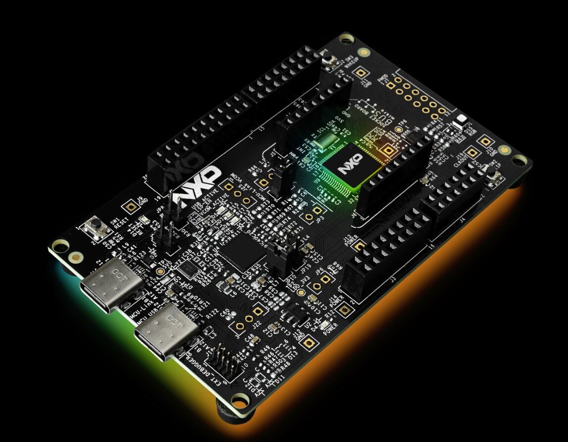
FRDM Training Hub

cancel
Showing results for 
Show  only  | Search instead for 
Did you mean: 

FRDM Training Hub

FRDM Training Hub


Restricted Beta Program

  • Comprehensive software and tools for seamless prototyping and rapid development
  • Scale your project with modular, quick-start FRDM and expansion boards
  • Leverage our application code hub or GoPoint to access 180+ code snippets and demos

  • Leverage FRDM Training Hub to learn from the experts
  • Not sure where to start ?

Discussions

Sort by:
Hands On In this lab we make some experience with the FRDM-MCXW23 board using the SDK project to implement a simple LED blinking. Once we will get familiar with the example project, we will integrate simple modifications.   Hardware Requirements Personal Computer FRDM-MCXW23 Board Type C USB Cable   Software Requirements IDE: Visual Studio Code 1.91.1 or newer Extension: MCUXpresso for VS Code v25.06.97 or newer SDK: SDK next gen v25.06.00 or newer SPSDK Tool Windows OS (It was used Windows 11 for this hands-on) Note: In order to make downloads in NXP website, it is necessary to have an account. Please, register and log-in for moving forward.   MCUXpresso for Visual Studio Code   MCUXpresso for Visual Studio Code (VS Code) provides an optimized embedded developer experience for code editing and development. The extension enables NXP developers to use one of the most popular embedded editors tools and provides an easy and fast way to create, build and debug applications based on MCUXpresso SDK or Zephyr projects.               Install it following the next steps: Download Visual Studio Code from Microsoft Store or visual studio code web page  Access to vscode for MCUX wiki and download MCUXpresso Installer  Run MCUXpresso Installer and for this Hands On install at least MCUXpresso SDK Developer Arm GNU Toolchain PEmicro   Installing the FRDM-MCXW23 SDK v 25.06.00 Each MCU has its own SDK that includes driver, examples, middleware, docs and other components. To get and build the demo, let’s install the SDK into VS Code:        Once MCUXpresso for Visual Studio Code is installed open VS Code. Go to MCUXpresso for VS Code extension that is on the tools column at the left. Look for INSTALLED REPOSITORIES option and press ‘+’. Detail steps are described in Use the steps for import a remote Git repository wiki page.      4.Search for FRDM-MCXW23 v25.06.00 SDK and complete installation. Lab Section: LED it Shine Open VSCode and follow the steps in this section to import the led_blinky example from SDK, belonging to the demo_apps section in the MCUXpresso SDK as per the following snapshot:       Click on Import button to import the full project into your workspace. Check the frdmmcxw23_led_blinky_lpc project in the Project explorer tab.                                   Build and Debug the project, follow the steps explained in the previous lab. Start the Debug session and hit the breakpoint at the first instruction in main, then click on Continue (F5) to start the debug session and you will see the RGB GREEN LED blinking at one second rate. Click on Stop (red square button) to stop the debugging. Note: User BLUE LED will continue blinking at the same rate as before because the Debug takes care about flashing the memory. Now is time to play with the code. In the next steps we will add a new blinking LED. Having a look at the schematic of the FRDM-MCXW23 board in the RGB LED section, we notice RED is connected to GPIO0_0 and BLUE is connected to GPIO0_4 while the RED LED (digging a little more in depth in the document) is connected to GPIO0_1.     What we want to do is to have a RED LED blinking at the same one second rate but will blink in the inverse time as the GREEN LED, this means when RED is on BLUE is off and vice versa.  To do this we will add few code modification. 1. Let us first explore a couple of defines part of the example. Open led_blinky.c file, at line 13 you will add the following two defines: #define RED_LED_PIN 1U #define RED_LED_PORT 0 Respectively these two are defining the new LED under control in the application, GPIO0 and pin 1 as per the schematic portion provided above. Have a look then in the code and you will see that at line 65 you will encounter the following function call GPIO_PortToggle(GPIO, BOARD_LED_PORT, 1u << BOARD_LED_PIN; This is the function that effectively toggles the LED under control. Let's modify the code to toggle the second LED and also add the name of the color. GPIO_PortToggle(GPIO, BOARD_LED_PORT, 1u << BOARD_LED_PIN; GPIO_PortToggle(GPIO, RED_LED_PORT, 1<< RED_LED_PIN; 2.Now, open the pin_mux.c file and look for BOARD_InitPins on line 67. In line 70 and 72 code enables the clock for the Iocon and GPIO0   /* Enables the clock for the I/O controller.: Enable Clock. */ CLOCK_EnableClock(kCLOCK_Iocon; /* Enables the clock for the GPIO0 module */ CLOCK_EnableClock(kCLOCK_Gpio0; Since BLUE LED is on the same port and GPIO group as RED LED we will not need to add a new one. 3. In line 76 we have the configuration for the GREEN LED  gpio_pin_config_t LED_BLUE_config = { .pinDirection = kGPIO_DigitalOutput, .outputLogic = 0U }; const uint32_t LED_BLUE = (/* Pin is configuBLUE as PIO0_19 */ IOCON_PIO_FUNC0 | /* No addition pin function */ IOCON_PIO_MODE_INACT | /* Standard mode, output slew rate control is enabled */ IOCON_PIO_SLEW_STANDARD | /* Input function is not inverted */ IOCON_PIO_INV_DI | /* Enables digital function */ IOCON_PIO_DIGITAL_EN | /* Open drain is disabled */ IOCON_PIO_OPENDRAIN_DI); /* PORT0 PIN19 (coords: 7) is configuBLUE as PIO0_19 */ IOCON_PinMuxSet(IOCON, BOARD_INITPINS_LED_BLUE_PORT, BOARD_INITPINS_LED_BLUE_PIN, LED_BLUE); Now we need to add the configuration for the RED LED, add the next code after BLUE LED configuration. Notice that default output logic is 1 the opposite of BLUE LED this will be use to have the opposite state when LEDs toggle. /* Initialize GPIO functionality on pin PIO0_1 */ GPIO_PinInit(BOARD_INITPINS_LED_RED_GPIO, BOARD_INITPINS_LED_RED_PORT, BOARD_INITPINS_LED_RED_PIN, &LED_RED_config); const uint32_t LED_RED = (/* Pin is configuBLUE as PIO0_19 */ IOCON_PIO_FUNC0 | /* No addition pin function */ IOCON_PIO_MODE_INACT | /* Standard mode, output slew rate control is enabled */ IOCON_PIO_SLEW_STANDARD | /* Input function is not inverted */ IOCON_PIO_INV_DI | /* Enables digital function */ IOCON_PIO_DIGITAL_EN | /* Open drain is disabled */ IOCON_PIO_OPENDRAIN_DI); /* PORT0 PIN19 (coords: 7) is configuBLUE as PIO0_19 */ IOCON_PinMuxSet(IOCON, BOARD_INITPINS_LED_RED_PORT, BOARD_INITPINS_LED_RED_PIN, LED_RED); 4. If you tried to compile now you will get some errors this is because we use some defines that are not created yet. Go to pin_mux.h, in this file we have definitions for BLUE LED as well starting on line 45. /* Symbols to be used with GPIO driver */ #define BOARD_INITPINS_LED_BLUE_GPIO GPIO /*!<@brief GPIO peripheral base pointer */ #define BOARD_INITPINS_LED_BLUE_GPIO_PIN_MASK (1U << 19U) /*!<@brief GPIO pin mask */ #define BOARD_INITPINS_LED_BLUE_PORT 0U /*!<@brief PORT peripheral base pointer */ #define BOARD_INITPINS_LED_BLUE_PIN 19U /*!<@brief PORT pin number */ #define BOARD_INITPINS_LED_BLUE_PIN_MASK (1U << 19U) /*!<@brief PORT pin mask */ Create defines for REDS LED, copy next test after BLUE LED defines #define BOARD_INITPINS_LED_RED_GPIO GPIO /*!<@brief GPIO peripheral base pointer */ #define BOARD_INITPINS_LED_RED_GPIO_PIN_MASK (1U << 1U) /*!<@brief GPIO pin mask */ #define BOARD_INITPINS_LED_RED_PORT 0U /*!<@brief PORT peripheral base pointer */ #define BOARD_INITPINS_LED_RED_PIN 1U /*!<@brief PORT pin number */ #define BOARD_INITPINS_LED_RED_PIN_MASK (1U << 1U) /*!<@brief PORT pin mask */ 5. Follow the steps described at point 3 to Build and Debug the application and hit the Continue button to start the debugging session. You will see the BLUE LED blinking at the same one second rate alternating with GREEN one. What if we want to change the blinking rate? Having a look at the led_blinky.c file, we notice there one special function called SysTick_Handler(void) defined at line 33. This is the interrupt routine associated to the so called Systick timer which is a timer embedded within the Cortex-M33 core typically used as a system tick for many RTOSes. The interrupt routine toggles the LED in use at a specific moment. We do not see any initialization function of it, though. The Systick Timer in this particular implementation is initialized by the function SysTick_Config(SystemCoreClock/1000U); invoked at line 59, this function simply initialize the internal SysTick Timer to a certain value taken as time base. The blinking delay is ensured by the  SysTick_Config(1000U) function called at line 69. Check what happens if you change the value of 1000U to another value.  6. Navigate to the ultimate call, and let us see what happens if we modify the call at line 69 like this: SysTick_DelayTicks(1000U/2); 7. Save the modification (CTRL+S), Build and start the debugging. What are you observing? Has the blinking rate changed, if yes, is it faster or slower? Congratulations, you have mastered the LED it shine Lab.  
View full article
This article will give a brief introduction of FRDM-IMX91S software release. FRDM-IMX Yocto BSP Release i.MX FRDM Development software release contains prebuilt images, documentation, and i.MX FRDM Yocto layer for FRDM-IMX boards. It also includes support for Matter.  Based on i.MX SW 2024 Q3 BSP release Linux kernel: 6.6.36_2.1.0 u-boot: 2024.04 i.MX FRDM Yocto layer source: https://github.com/nxp-imx-support/meta-imx-frdm For more details, please check i.MX FRDM Software User Guide. FRDM-IMX91S accessories and corresponding dtb: 5-inch Tianma LCD: imx91-11x11-frdm-imx91s-tianma-wvgapanel. dtb RPI-CAM-INTB: imx91-11x11-frdm-imx91s-mt9m114.dtb MX93AUD-HAT: imx91-11x11-frdm-imx91s-aud-hat.dtb 8MIC-RPI-MX8: imx91-11x11-frdm-imx91s-8mic.dtb Build FRDM-IMX91S SD boot image: Download i.MX SW 2024 Q3 Release: $ repo init -u https://github.com/nxp-imx/imx-manifest -b imx-linux-scarthgap -m imx-6.6.36-2.1.0.xml $ repo sync Integrate meta-imx-frdm layer into Yocto code base: $ cd ${MY_YOCTO}/sources $ git clone https://github.com/nxp-imx-support/meta-imx-frdm.git Yocto Project Setup: $ cd ${MY_YOCTO} $ MACHINE=imx91frdmimx91s DISTRO=fsl-imx-xwayland source sources/meta-imx-frdm/tools/imx-frdm-setup.sh -b frdm-imx91s Build images: $ bitbake imx-image-full Flash SD card image using dd: $ zstdcat imx-image-full-imx91frdmimx91s.rootfs.wic.zst | sudo dd of=/dev/sdx bs=1M && sync Or use uuu to burn image to SD card: $ uuu -b sd_all imx-image-full-imx91frdmimx91s.rootfs.wic.zst Build FRDM-IMX91S NAND boot image: Download i.MX SW 2024 Q3 Release: $ repo init -u https://github.com/nxp-imx/imx-manifest -b imx-linux-scarthgap -m imx-6.6.36-2.1.0.xml $ repo sync Integrate meta-imx-frdm layer into Yocto code base: $ cd ${MY_YOCTO}/sources $ git clone https://github.com/nxp-imx-support/meta-imx-frdm.git Yocto Project Setup: $ cd ${MY_YOCTO} $ MACHINE=imx91frdmimx91s DISTRO=fsl-imx-xwayland source sources/meta-imx-frdm/tools/imx-frdm-setup.sh -b frdm-imx91s Configure U-Boot to nand boot: $ echo "UBOOT_CONFIG = \"nand\"" >> conf/local.conf Build base rootfs: $ bitbake imx-image-base Build initramfs: $ bitbake fsl-image-mfgtool-initramfs Use uuu script to flash nand boot image:  $ sudo uuu example_kernel_nand.uuu FRDM-IMX91S Matter support  Based on i.MX Matter 2024 Q3. To include Matter support, please follow below steps to include Matter layer into Yocto build. Download i.MX SW 2024 Q3 BSP Release: $ repo init -u https://github.com/nxp-imx/imx-manifest -b imx-linux-scarthgap -m imx-6.6.36-2.1.0.xml $ repo sync Download i.MX Matter Yocto layer: $ cd ${MY_YOCTO}/sources/meta-nxp-connectivity $ git remote update $ git checkout imx_matter_2024_q3 Integrate meta-imx-frdm layer into Yocto code base: $ cd ${MY_YOCTO}/sources $ git clone https://github.com/nxp-imx-support/meta-imx-frdm.git Yocto Project Setup: $ cd ${MY_YOCTO} $ MACHINE=imx91frdmimx91s-iwxxx-matter DISTRO=fsl-imx-xwayland source sources/meta-imx-frdm/tools/imx-frdm-matter-setup.sh bld-xwayland-frdmimx91s Build images:  $ bitbake imx-image-multimedia Related Documentation i.MX FRDM Software User Guide More information about i.MX productions can be found at(http://www.nxp.com/imxlinux) i.MX Yocto Project User’s Guide​ i.MX Linux User’s Guide​ i.MX Linux Reference Manual​ i.MX Porting Guide
View full article
This article will give a brief introduction of FRDM-IMX8MPLUS software release, including Yocto BSP release and Debian release. FRDM-IMX Yocto BSP Release i.MX FRDM Development software release contains prebuilt images, documentation, and i.MX FRDM Yocto layer for FRDM-IMX boards. It also includes support for Matter.  Based on i.MX SW 2024 Q3 BSP release Linux kernel: 6.6.36_2.1.0 u-boot: 2024.04 i.MX FRDM Yocto layer source: https://github.com/nxp-imx-support/meta-imx-frdm For more details, please check i.MX FRDM Software User Guide. FRDM-IMX8MPLUS accessories and corresponding dtb: 7-inch Waveshare LCD: imx8mp-frdm-waveshare.dtb DY1212W-4856 LVDS: imx8mp-frdm-boe-wxga-lvds0-panel.dtb imx8mp-frdm-boe-wxga-lvds1-panel.dtb RPI-CAM-MIPI MIPI CSI: imx8mp-frdm-ap1302.dtb imx8mp-frdm-dual-ap1302.dtb IMX-OS08A20 MIPI CSI: imx8mp-frdm-os08a20.dtb imx8mp-frdm-dual-os08a20.dtb 8MIC-RPI-MX8: imx8mp-frdm-8mic.dtb 2EL M.2 Module: imx8mp-frdm-iw612-otbr.dtb Build FRDM-IMX8MPLUS Yocto image: Download i.MX SW 2024 Q3 release: $ repo init -u https://github.com/nxp-imx/imx-manifest -b imx-linux-scarthgap -m imx-6.6.36-2.1.0.xml $ repo sync Integrate meta-imx-frdm layer into Yocto code base: $ cd ${MY_YOCTO}/sources $ git clone https://github.com/nxp-imx-support/meta-imx-frdm.git Yocto project setup: $ cd ${MY_YOCTO} $ MACHINE=imx8mpfrdm DISTRO=fsl-imx-xwayland source sources/meta-imx-frdm/tools/imx-frdm-setup.sh -b frdm-imx8mp Build images: $ bitbake imx-image-full Flash SD card image using dd: $ zstdcat imx-image-full-imx8mpfrdm.rootfs.wic.zst | sudo dd of=/dev/sdx bs=1M && sync Or use uuu to burn image to SD card: $ uuu -b sd_all imx-image-full-imx8mpfrdm.rootfs.wic.zst FRDM-IMX8MPLUS Matter Support Based on i.MX Matter 2024 Q3 To include Matter support, please follow below steps to include Matter layer into Yocto build. Download i.MX SW 2024 Q3 BSP Release: $ repo init -u https://github.com/nxp-imx/imx-manifest -b imx-linux-scarthgap -m imx-6.6.36-2.1.0.xml $ repo sync Download i.MX Matter Yocto layer: $ cd ${MY_YOCTO}/sources/meta-nxp-connectivity $ git remote update $ git checkout imx_matter_2024_q3 Integrate meta-imx-frdm layer into Yocto code base: $ cd ${MY_YOCTO}/sources $ git clone https://github.com/nxp-imx-support/meta-imx-frdm.git Yocto Project Setup: $ cd ${MY_YOCTO} $ MACHINE=imx8mpfrdm-matter DISTRO=fsl-imx-xwayland source sources/meta-imx-frdm/tools/imx-frdm-matter-setup.sh bld-xwayland-imx8mpfrdm Build images: $ bitbake imx-image-multimedia FRDM-IMX8MPLUS Debian Release FRDM-IMX8MPLUS has support on Debian 12 OS. i.MX Debian Linux SDK distribution is a combination of NXP-provided kernel and boot loaders with a Debian distro user-space image, which includes: Debian-based rootfs Debian Base (basic packages) Debian Server (more packages without GUI Desktop) Debian Desktop (with GNOME GUI Desktop) Linux kernel BSP components various applications (graphics, multimedia, networking, connectivity, security, and AI/ML) For more details of NXP Debian Linux SDK Distribution, please check NXP Debian Linux SDK User Guide. Quick Start with Debian: To create an SD card with Debian for FRDM-IMX8MPLUS, please follow below steps. Download flex-installer on the Linux host $ wget http://www.nxp.com/lgfiles/sdk/lsdk2412/flex-installer $ chmod +x flex-installer $ sudo mv flex-installer /usr/bin Plug the SD card into the Linux host and install the images as below # format SD card $ flex-installer -i pf -d /dev/sdx # automatically download and install images into SD card $ flex-installer -i auto -d /dev/mmcblk1 -m imx8mpfrdm Plug the SD card into FRDM-IMX8MPLUS board and install the extra packages as below  1. Setup Ethernet network interface by DHCP or setting it manually $ dhclient -i end0 2. Set correct system time, for example $ date -s "22 Nov 2024 09:00:00" 3. Install extra packages for GNOME GUI Desktop version $ debian-post-install-pkg desktop 4. Or install extra packages for Server version without GUI Desktop $ debian-post-install-pkg server 5. After finishing the installation, run the reboot command to boot up the Debian Desktop/Server system Building Debian Images with Flexbuild: To build Debian image with Flexbuild for FRDM-IMX8MPLUS, please follow below steps. Set up the build environment $ git clone https://github.com/nxp/flexbuild $ cd flexbuild && source setup.env #Continue to run commands below in case you need to build in Docker due to lack of Ubuntu 22.04 or Debian 12 host $ bld docker $ source setup.env Build image with Flexbuild $ bld -m imx8mpfrdm Flexbuild usage: To build individual part of the image, please check below command list for Flexbuild usage. $ bld uboot -m imx8mpfrdm (compile u-boot image for imx8mpfrdm) $ bld linux (compile linux kernel for all arm64 i.MX machines) $ bld bsp -m imx8mpfrdm (generate BSP firmware) $ bld boot (generate boot partition tarball including kernel, dtb, modules, distro bootscript for iMX machines) $ bld multimedia (build multimedia components for i.MX platforms) $ bld rfs -r debian:server (generate Debian server rootfs) $ bld apps -r debian:server (compile apps against runtime dependencies of Debian server RootFS) $ bld merge-apps -r debian:server (merge iMX-specific apps into target Debian server RootFS) $ bld packrfs -r debian:server (pack and compress target debian server rootfs) Related Documentation i.MX FRDM Software User Guide i.MX Debian Linux SDK User Guide More information about i.MX productions can be found at(http://www.nxp.com/imxlinux) i.MX Yocto Project User’s Guide​ i.MX Linux User’s Guide​ i.MX Linux Reference Manual​ i.MX Porting Guide Debian documents at http://www.nxp.com/nxpdebian
View full article
Hands-on training utilizing NVIDIA's TAO toolkit and FRDM-IMX93
View full article
Customer may want to deploy Android 14 on FRDM-iMX8MP. This doc gives an introduction about how to deploy Android OS14 on FRDM-iMX8MP   Hardware: FRDM-iMX8MP, Power supply cable, usb cable x2,  Ubuntu PC Outline: Follow the below steps: Setup the Android 14 source environment based on LF6.6.36. Apply FRDM-iMX8MP patches in kernel, uboot, mkimage, and device directory. Build the image for FRDM-iMX8MP Flash the image   1. Setup the environment On the Linux PC, set up the Android Source environment according to Section 2- Section 3 from the Android User’s Guide Rev. android-14.0.0_2.1.0 and do not build the image yet. $ cd ~ (or any other directory you like) $ tar xzvf imx-android-14.0.0_2.1.0.tar.gz To generate the i.MX Android release source code build environment, execute the following commands: $ source ~/imx-android-14.0.0_2.1.0/imx_android_setup.sh Prepare the build environment for U-Boot and Linux kernel. This step is mandatory because there is no GCC cross-compile tool chain in the one in AOSP codebase. An approach is provided to use the self-installed GCC cross-compile tool chain for both AArch32 and AArch64. Change to the top-level build directory and set up the environment for building. This only configures the current terminal $ cd ${MY_ANDROID} $ source build/envsetup.sh 2. Apply FRDM-iMX8MP patches into AOSP   Apply the patch in device/nxp, copy all the patches into android_build/device/nxp, and then running the command: $ git apply --check 0001-device-nxp-add-FRDM-i.MX8MP-Android14-basic-support.patch $ git apply 0001-device-nxp-add-FRDM-i.MX8MP-Android14-basic-support.patch Apply the patches in uboot, copy all the patches into android_build/vendor/nxp-opensource/uboot-imx, and then running the command: $ git am *.patch Apply the patches in kernel, copy all the patches into android_build/vendor/nxp-opensource/kernel-imx, and then running the command: $ git am *.patch Apply the patch in mkimage, copy all the patches into android_build/vendor/nxp-opensource/ imx-mkimage, and then running the command: $ git am *.patch     3. Build the image for FRDM-iMX8MP Execute the Android lunch command: $ lunch frdm_8mp-trunk_staging-userdebug Execute the imx-make.sh script to generate the image. $ ./imx-make.sh -j4 2>&1 | tee build-log.txt NOTE: The following outputs are generated by default in ${MY_ANDROID}/out/target/product/frdm_8mp:   4. Flash the image The board image files can be flashed into the target board using Universal Update Utility (UUU). For the UUU binary file, download it from GitHub: uuu release page on GitHub.  To achieve more flexibility, two script files are provided to invoke UUU to automatically flash all Android images. uuu_imx_android_flash.sh for Linux OS uuu_imx_android_flash.bat for Windows OS For this release, these two scripts are validated on UUU 1.5.179 version. Download the corresponding version from GitHub: For Linux OS, download the file named uuu. For Windows OS, download the file named uuu.exe. Perform the following steps to download the board images: Download the UUU binary file from GitHub as described before. Install UUU into a directory contained by the system environment variable of "PATH". Make the board enter serial download mode. Change the board's SW5 (boot mode) to 0001 (from 1-4 bit) to enter serial download mode. Power on the board. Use the USB cable to connect the USB 3.0 dual-role port (with silkprint "PORT1") on the board to your host PC. On the Linux system, open the shell terminal. For example, you can execute a command as follows: $ sudo ./uuu_imx_android_flash.sh -f imx8mp -p frdm -a -e On the Windows system, open the command-line interface in administrator mode. The corresponding command is as follows: $ uuu_imx_android_flash.bat -f imx8mp -p frdm -a -e NOTE: If you want to change the dtb, you can add -d dtb_feature. Also, you can check all the info by using the command: uuu_imx_android_flash.bat Power off the board and Change the board's SW5 (boot mode) to 0010 (from 1-4 bit) to enter emmc boot mode
View full article
  The FRDM i.MX 8M Plus development board is a low-cost and compact development board with NXP i.MX 8M Plus applications processor. On-board NXP IW612 Tri-Radio module supports Wi-Fi 6 + Bluetooth Low Energy 5.4 + 802.15.4. NXP releases Debian every six months and releases Yocto every year for this board. The FRDM i.MX 8M Plus development board is ideal for developing modern Industrial and IoT applications.   Get to know FRDM-IMX8MPLUS Development Boaard     Specifications 4× Arm® Cortex®A53 + 1× Arm Cortex-M7 LPDDR4 32-bit 4GB eMMC 5.1, 32GB QSPI NOR flash, 32 MB Power Management IC (PMIC) MicroSD 3.0 card slot One USB 3.0 Type-C connector One USB 2.0 Type-C for debug One USB 3.0 Type-A connector One USB Type-C PD only Onboard Wi-Fi® 6 + Bluetooth® LE 5.4/802.15.4 module Optional M.2 Key-E for Wi-Fi/ BT/802.15.4 M.2 Key-M for SSD Multiple display interface:     MIPI-DSI connector 2x4 data lane LVDS w/ Backlight HDMI connector Two MIPI-CSI connectors One 2x5 Pin NXP custom interface with: One CAN port I2C expansion Two 1 Gbps Ethernet Port0 supports POE Port1 supports TSN External RTC with coin cell connector 40 pin (2 x 20) expansion I/O     Feature FRDM-IMX8MPLUS eMMC 32GB DRAM Micron 4GB PMIC PCA9450C WiFi Module u-blox MAYA-W276 on-board USB Type-C+Type-A ENET 2xGbE M.2 (Key E) SDIO WiFi / BT Y (rework needed) M.2 (Key M) PCIE Y HDMI Y MIPI DSI Panel 22 Pins FPC HDR LVDS Panel 40 Pins 2mm HDR MIPI CSI camera 22 Pins FPC HDR 2x20 Expansion Interface Y CAN BUS Y MicroSD Y UART Y Audio WM8962B Remote Debug N NXP Connector (CAN, I2C) Y Power Connector Type-C PCB layers 6 Board DIM 12x13cm       NXP Devices On-Board PMIC PCA9450C USB PD TCPC PHY IC PTN5110 High-Voltage USB PD Power Switch NX20P5090UK I2C  Extends  GPIO PCAL6416A USB3.0 Switch CBTL02043A I2C Repeater PCA9509PDP Bi-directional Level Shifter NTS0104 CAN Transceiver TJA1051T/3 USB Sink & Source combo power switch NX20P3483UK USB Type-C CC and SBU Protection IC NX20P0407 Real-time clock/calendar PCF2131 Wi-Fi, BT, 802.15.4 Tri-Radio IW612 (in u-blox Module)     Expansion Boards RPI-CAM-MIPI: IAS camera to 22 Pins FPC camera adapter Waveshare 7'' DSI LCD: 7inch Capacitive Touch, 1024×600 DY1212W-4856 TFT LCD panel with LVDS interface: 12.1" (WXGA) TFT LCD panel with LVDS interface ​8MIC-RPI-MX8: 8-microphone array proto board for voice enablement   Trainings   Generic FRDM-IMX8MPLUS Software Release Deploy Android14 on FRDM-iMX8MP Lf6.6.36   Useful Links −i.MX Yocto Project User’s Guide​ −i.MX Linux User’s Guide ​−i.MX Linux Reference Manual​ −i.MX Porting Guide -i.MX Debian Linux SDK User Guide
View full article
Bring up Wi-Fi and Bluetooth interface. Configure and bring up Bluetooth A2DP sink profile. Configure and bring up Wi-Fi STA mode and perform throughput test. Bluetooth A2DP Sink profile configurations STA mode creation Connection of STA device to Ext AP Execution of udhcp client to receive the dynamic IP address from Ext AP iPerf server execution on Ubuntu/Windows machine iPerf client execution on FRDM i.MX 93 board 802.15.4 configuration on FRDM i.MX 93 board Wi-Fi Bluetooth LE and OT COEX Hands-on Demo Guide  Community Support If you have questions regarding this training, please leave your comments in our Wireless MCU Community! here 
View full article
In this lab, you will learn how to: Load wireless module into board Bring-up Bluetooth + 802.15.4 firmware Initialize the 802.15.4 interface on the FRDM-i.MX93 board. Configure and bring up the 802.15.4 interface. Create a thread network. Add nodes to the thread network. Verify thread network connectivity. Exchange data between thread nodes.   OpenTread Hands-on Demo Guide  Community Support If you have questions regarding this training, please leave your comments in our Wireless MCU Community! here 
View full article
Load drivers of wireless module into board Bring-up Bluetooth Scan/pair/connect Bluetooth with smartphone Hands-on Bluetooth A2DP sink/source profile demo play audio on remote Bluetooth headset or speaker using Bluetooth A2DP source profile play audio on FRDM i.MX 93 board from smart phone using Bluetooth A2DP sink profile Bluetooth A2DP Source and Sink Profile Demo    Community Support If you have questions regarding this training, please leave your comments in our Wireless MCU Community! here 
View full article
The FRDM-i.MX93 development board is designed to support advanced applications such as Industrial and Consumer HMI, Edge AI, Interconnected Devices, and High-Performance IoT Solutions. Built with NXP's i.MX 93 applications processor, it offers robust features like efficient machine learning acceleration, enhanced multimedia capabilities, and advanced connectivity options. This document provides a detailed guide on setting up the FRDM-i.MX93 development board. It includes hardware connections, flashing the Linux image, and accessing the debug console for seamless development and prototyping. FRDM-IMX93 Board Flashing Guide  Community Support If you have questions regarding this training, please leave your comments in our Wireless MCU Community! here 
View full article
i.MX FRDM Development (FRDM) software release contains prebuilt images, documentation, and i.MX FRDM Yocto layer for FRDM-IMX boards. It also includes support for Matter and Debian release. This article will give a brief introduction of FRDM-IMX91 software release. For more details, please check i.MX FRDM Software User Guide. FRDM-IMX91 Yocto BSP Release Based on i.MX SW 2024 Q3 BSP release Linux kernel: 6.6.36_2.1.0 u-boot: 2024.04 i.MX FRDM Yocto layer source: https://github.com/nxp-imx-support/meta-imx-frdm FRDM-IMX91 BSP changes: U-boot: Add basic support for FRDM-IMX91 Kernel: Add basic support for FRDM-IMX91 and add support for kinds of accessories FRDM-IMX91 Yocto layer: Add Yocto layer for FRDM-IMX91 and integrate u-boot/kernel patches FRDM-IMX91 accessories and corresponding dtb: 5 inch Tianma LCD: imx91-11x11-frdm-tianma-wvga-panel.dtb RPI-CAM-INTB: imx91-11x11-frdm-mt9m114.dtb MX91AUD-HAT or MX91AUD-HAT + 8MIC-RPI-MX8: imx91-11x11-frdm-aud-hat.dtb 8MIC-RPI-MX8: imx91-11x11-frdm-8mic.dtb 2LL M.2 Module: imx91-11x11-frdm.dtb Build FRDM-IMX91 Yocto Image: Download i.MX SW 2024 Q3 Release: $ repo init -uhttps://github.com/nxp-imx/imx-manifest-b imx-linux-scarthgap -m imx-6.6.36-2.1.0.xml $ repo sync Integrate meta-imx-frdm layer into Yocto code base: $ cd ${MY_YOCTO}/sources $ git clone https://github.com/nxp-imx-support/meta-imx-frdm.git Yocto Project Setup: $ cd ${MY_YOCTO} $ MACHINE=imx91frdm DISTRO=fsl-imx-xwayland source sources/meta-imx-frdm/tools/imx-frdm-setup.sh -b frdm-imx91 Build images: $ bitbake imx-image-full Flashing SD card image using dd: $ zstdcat imx-image-full-imx91frdm.rootfs.wic.zst | sudo dd of=/dev/sdx bs=1M && sync Or using uuu to burn image to SD card: $ uuu -b sd_all imx-image-full-imx91frdm.rootfs.wic.zst FRDM-IMX91 Matter Support Based on i.MX Matter 2024 Q3 To include Matter support, please follow below steps to include Matter layer into Yocto build. Download i.MX SW 2024 Q3 BSP Release: $ repo init -u https://github.com/nxp-imx/imx-manifest -b imx-linux-scarthgap -m imx-6.6.36-2.1.0.xml $ repo sync Download i.MX Matter Yocto layer: $ cd ${MY_YOCTO}/sources/meta-nxp-connectivity $ git remote update $ git checkout imx_matter_2024_q3 Integrate meta-imx-frdm layer into Yocto code base: $ cd ${MY_YOCTO}/sources $ git clone https://github.com/nxp-imx-support/meta-imx-frdm.git Yocto Project Setup: $ cd ${MY_YOCTO} $ MACHINE=imx91frdm-iwxxx-matter DISTRO=fsl-imx-xwayland source sources/meta-imx-frdm/tools/imx-frdm-matter-setup.sh bld-xwayland-imx91 Build images: $ bitbake imx-image-multimedia FRDM-IMX91 Debian Release FRDM-IMX91 has support for Debian 12 OS. i.MX Debian Linux SDK distribution is a combination of NXP-provided kernel and boot loaders with a Debian distro user-space image, which includes: Debian-based rootfs Debian Base (basic packages) Debian Server (more packages without GUI Desktop) Debian Desktop (with GNOME GUI Desktop) Linux kernel BSP components various applications (graphics, multimedia, networking, connectivity, security, and AI/ML) For more details of NXP Debian Linux SDK Distribution, please check NXP Debian Linux SDK Distribution for i.MX and Layerscape. Quick Start with Debian: To create an SD card with Debian for FRDM-IMX91, please follow below steps. Download flex-installer on the Linux host $ wget http://www.nxp.com/lgfiles/sdk/lsdk2412/flex-installer $ chmod +x flex-installer $ sudo mv flex-installer /usr/bin Plug the SD card into the Linux host and install the images as below # format SD card $ flex-installer -i pf -d /dev/sdb # automatically download and install images into SD card $ flex-installer -i auto -d /dev/mmcblk1 -m imx91frdm Plug the SD card into the FRDM-IMX91 board and install the extra packages as below         1. Setup Ethernet network interface by DHCP or setting it manually $ dhclient -i end0         2. Set correct system time, for example $ date -s "22 Nov 2024 09:00:00"         3. Install extra packages for GNOME GUI Desktop version $ debian-post-install-pkg desktop         4. Or install extra packages for Server version without GUI Desktop $ debian-post-install-pkg server         5. After finishing the installation, run the reboot command to boot up the Debian Desktop/Server system  Building Debian Images with Flexbuild: To build Debian image with Flexbuild for FRDM-IMX91, please follow below steps. Set up the build environment $ git clone https://github.com/nxp/flexbuild $ cd flexbuild && source setup.env #Continue to run commands below in case you need to build in Docker due to lack of Ubuntu 22.04 or Debian 12 host $ bld docker $ source setup.env Build image with Flexbuild $ bld -m imx91frdm Flexbuild usage: To build individual part of the image, please check below command list for Flexbuild usage $ bld uboot -m imx91frdm (compile u-boot image for imx91frdm) $ bld linux (compile linux kernel for all arm64 i.MX machines) $ bld bsp -m imx91frdm (generate BSP firmware) $ bld boot (generate boot partition tarball including kernel, dtb, modules, distro bootscript for iMX machines) $ bld multimedia (build multimedia components for i.MX platforms) $ bld rfs -r debian:server (generate Debian server rootfs) $ bld apps -r debian:server (compile apps against runtime dependencies of Debian server RootFS) $ bld merge-apps -r debian:server (merge iMX-specific apps into target Debian server RootFS) $ bld packrfs -r debian:server (pack and compress target debian server rootfs) Related Documentation FRDM-IMX91 Documents: FRDM-IMX91 Quick Start Guide FRDM-IMX91 Board User Manual i.MX FRDM Software User Guide More information about i.MX productions can be found at(http://www.nxp.com/imxlinux) i.MX Yocto Project User’s Guide​ i.MX Linux User’s Guide​ i.MX Linux Reference Manual​ i.MX Porting Guide Debian documents at http://www.nxp.com/nxpdebian i.MX Debian Linux SDK User Guide
View full article
FRDM-IMX91 Hardware Introduction The FRDM i.MX 91 development board is a low-cost and compact development board with NXP i.MX91 applications processor. On-board NXP IW610 Tri-Radio module supports Wi-Fi 6 + Bluetooth Low Energy 5.4 + 802.15.4. NXP releases Debian every six months and releases Yocto every year for this board. The FRDM i.MX 91 development board is ideal for developing modern Industrial and IoT applications. Get to know FRDM-IMX 91 Development Board   Specifications: 1x Arm® Cortex®-A55​ MAYA-W476-00B, Wi-Fi + BLE 5.4 + 802.15.4​​ Module on-board, IW610 2x GbE Ethernet (1xETER, 1xTSN) M.2 Key-E for Wi-Fi/BLE/802.15.4​ LPDDR4 16-bit 1GB eMMC 5.1, 8GB MicroSD 3.0 card slot 3x USB 2.0 Type-C connector (1-Debug, 1-PD, 1-USB2.0) + One USB 2.0 Type-A​ 40 pin (2x20) Expansion I/O One 2x5 Pin NXP interface (1- CAN, Two channels for ADC, I2C/I3C expansion)   Features FRDM-IMX91 eMMC 8GB DRAM NANYA 1GB PMIC PCA9451 WiFi Module u-blox MAYA-W476-00B on-board USB TYPE Type-C+Type-A ENET 2xGbE M.2 (Key E) SDIO Wi-Fi / BLE Y (rework needed) HDMI N Display (Parallel RGB LCD) 2x20 EXPI Camera (Parallel Camera) 2x20 EXPI 2x20 Expansion Interface Y CAN BUS Y MicroSD Y UART Y Audio  MQS Remote Debug N Power Connector Type-C PCB layers 10 Base Board DIM 6.5x10.5cm     NXP Devices On-board   PMIC PCA9451AHNY Real time clock/calendar PCF2131 WIFI/BLE/802.15.4 Tri-Radio IW610 in u-blox module CAN Transceiver TJA1051T/3 USB Type-C CC and SBU Protection IC NX20P0407  High-Voltage USB PD Power Switch NX20P5090UK USB PD and Type-C High-Voltage Sink/Source Combo Switch with Protection NX20P3483UK IIC Extends GPIO PCAL6524/ PCAL6408A Expansion Boards TM050RDH03-41: LCD display module 5” TFT 800X480, RGB, 120.7 mm x75.8 mm7inch MX93AUD-HAT: Audio expansion board with multiple features ​8MIC-RPI-MX8: 8-microphone array proto board for voice enablement Trainings   FRDM-IMX91 SW Release Package  FRDM-IMX91 Connectivity training   Documentation  −FRDM-IMX91 Quick Start Guide −FRDM-IMX91 Board User Manual -FRDM-IMX91 Software User Guide   Useful Links −i.MX Yocto Project User’s Guide​ −i.MX Linux User’s Guide ​−i.MX Linux Reference Manual​ −i.MX Porting Guide -i.MX Debian Linux SDK User Guide
View full article
In this lab, you will learn how to: Bring up Wi-Fi interfaces. Run basic Wi-Fi scan Configure and bring up Wi-Fi STA mode using WPA_SUPPLICANT. Configure and bring up UDHCP server for dynamic IP assignment for associated client devices. Run UDHCP client to get dynamic IP address. Configure and bring up Wi-Fi AP mode using hostapd. Connect STA to external AP Connect AP to external STA Start ping  Wi-Fi Basic Hands on Demo Guide Video   Community Support If you have questions regarding this training, please leave your comments in our Wireless MCU Community! here 
View full article
The FRDM-i.MX 91 development board enables Advance HMI Solutions supporting Industrial and consumer HMI, Enriched user experience, Immersive Audio Processing, Voice Solutions, and Interconnected Devices (smarter edge devices) among other applications. This document explains how to set up FRDM-i.MX 91 development board. This includes the hardware connections, flashing the Linux image, and accessing the debug console.   FRDM-IMX91 Board Flashing Guide Video   Community Support If you have questions regarding this training, please leave your comments in our Wireless MCU Community! here 
View full article
In this lab, you will learn how to: Bring up Wi-Fi and Bluetooth interface. Configure and bring up Bluetooth A2DP sink profile. Configure and bring up Wi-Fi STA mode and perform throughput test. Bluetooth LE GATT profile configurations STA mode creation Connection of STA device to Ext AP Execution of udhcp client to receive the dynamic IP address from Ext AP iPerf server execution on Ubuntu/Windows machine iPerf client execution on FRDM i.MX 91 board OT child configuration on FRDM i.MX 91 board Wi-Fi Bluetooth LE and OT COEX Hands-on Demo Guide Video   Community Support If you have questions regarding this training, please leave your comments in our Wireless MCU Community! here 
View full article
In this lab, you will learn how to: Load wireless module into board Bring-up Bluetooth The bring-up of 802.15.4 Initialize the 802.15.4 interface on the FRDM-i.MX91 board. Configure and bring up the 802.15.4 interface. Create a thread network. Add nodes to the thread network. Verify thread network connectivity. Exchange data between thread nodes.   OpenTread Hands-on Demo Guide Video   Community Support If you have questions regarding this training, please leave your comments in our Wireless MCU Community! here 
View full article
In this lab, you will learn how to:   Bring-up Bluetooth interface. The LE GATT profile defines the way that two Bluetooth LE devices transfer the data using concept of Services and Characteristics. Configure and bring up Bluetooth LE GATT server profile using NXP-based IW610 module. Configure and bring up Bluetooth LE GATT client profile using NXP-based IW610 module. nRF connect smartphone application is used to run the LE GATT server with the help of predefined Heart Rate Service.   Bluetooth LE GATT Profile Demo Guide Lab Video   Community Support If you have questions regarding this training, please leave your comments in our Wireless MCU Community! here 
View full article
This document assumes FRDM-iMX91 board is flashed with a Linux image. For flashing instructions, refer to FRDM-iMX91_Board_Flashing guide. Then, follow this document to download software applications to test Wi-Fi, Bluetooth, and 802.15.4 performance. Hardware Prerequisites Windows or Linux PC with 64-bit OS 2 spare USB ports on PC FRDM-iMX91 Development Board Bluetooth LE device: Mobile phone which can configured as central or peripheral Wi-Fi Access Point: Standalone or mobile hotspot Wi-Fi Station: Mobile phone used as a station OPENTHREAD: 1 Another OT enabled board   Required PC Software   Serial Terminal program Setting for terminal: Baud rate:115200, Parity: none, Data bits: 8, Stop bits: 1 Windows:   PUTTY or teraterm  and USB Device driver  Linux:           Minicom (Command to download the tool : sudo apt-get install minicom)   Iperf Windows:    Download Iperf version 3.0.11 from here. Linux:            Download Debian package of IPerf 3.0.11 for Ubuntu 16.04 from here. $ wget https://iperf.fr/download/ubuntu/iperf3_3.0.11-1_amd64.deb   Install the package using the command below. $ sudo dpkg -i /path/to/package/iperf3_3.0.11-1_amd64.deb   Required Mobile Software   Iperf Application (iperf 3) Android:  HE.NET Network Tools on Google Play iOS:   HE.NET Network Tools on AppStore   nRF Connect Application Android:   nRF Connect on Google Play iOS:    nRF Connect on App Store   Required EVK Software Linux BSP Image  Version: L6.6.52_2.2.0 Link: https://www.nxp.com/webapp/sps/download/license.jsp?colCode=L6.6.52_2.2.0_MX91&appType=file1&DOWNLOAD_ID=null   To download the pre-built image, please refer to https://www.nxp.com/design/design-center/software/embedded-software/i-mx-software/embedded-linux-for-i-mx-applications-processors:IMXLINUX   hands-on Labs   Lab1 - WIFI Hands-on Lab2 - Bluetooth LE GATT Profile  Lab3 - OpenThread  Lab4-WIFI_Bluetooth-LE_OpenThread   Community Support If you have questions regarding this training, please leave your comments in our Wireless MCU Community! here   
View full article
FRDM-IMX93 development boards are the first FRDM development board with i.MX MPUs and include Wi-Fi and Bluetooth modules and support for Debian, Yocto and GoPoint which will help you to develop your industrial and IoT applications quickly with NXP's developer experience.   FRDM-IMX93 Applications Low-cost development board usage, Bi-annual BSP release for Debian Yearly BSP release for Yocto.   Get to know FRDM-IMX 93 Development Board       Specifications 2x Arm Cortex®-A55 + Cortex®-M33 Wi-Fi 6 + BT + 802.15.4 Module on-board, IW612 2x GB Ethernet (1xETER, 1xTSN) MIPI-CSI/DSI, HDMI M.2 Connector LPDDR4X 16-bit 2GB eMMC 5.1, 32GB MicroSD 3.0 card slot 3x USB 2.0 Type-C connector (one for Debug, one PD only) + 1x USB 2.0 Type-A RTC, Buttons and LED     Feature FRDM-IMX93 eMMC 32GB DRAM Micron 2GB PMIC PCA9451A WiFi Module u-blox MAYA-W276 on-board USB TYPE C Type-C+Type-A ENET 2xGbE M.2 (Key E) SDIO WiFi / BT Y (rework needed) HDMI IT6263/Y MIPI DSI Panel 22 Pins FPC HDR LVDS Panel N MIPI CSI camera 22 Pins FPC HDR 2x20 Expansion Interface Y CAN BUS Y MicroSD Y UART Y Audio  MQS Remote Debug N NXP Connector (CAN,ADC, I2C) Y Power Connector Type-C PCB layers 10 Base Board DIM 6.5x10.5cm   NXP Devices On-Board PMIC PCA9451A USB PD TCPC PHY IC PTN5110 High-Voltage USB PD Power Switch NX20P5090UK IIC  Extends  GPIO PCAL6524/PCAL6408A CAN Transceiver TJA1051T/3 USB Sink & Source combo power switch  NX20P3483UK USB Type-C CC and SBU Protection IC  NX20P0407 Real-time clock/calendar PCF2131 Wi-Fi, BT, 802.15.4 Tri-Radio IW612 (in u-blox Module)   Expansion Boards   RPI-CAM-MIPI: IAS camera to 22 Pins FPC camera adapter TM050RDH03-41: LCD display module 5” TFT 800X480, RGB, 120.7 mm x75.8 mm7inch Waveshare 7'' DSI LCD: (English language link) 7inch Capacitive Touch, 1024×600 MX93AUD-HAT: Audio expansion board with multiple features ​8MIC-RPI-MX8: 8-microphone array proto board for voice enablement   FRDM-IMX93 web page Getting Started Guide Out of the Box Get Software Build and Run Developer Experience   Projects and Tutorials Debug Terminal in Linux & Windows Cortex-M33 Enablement Deploy ML models on NPU Graphics Security and Integrity Fast Boot Trainings   FRDM-IMX93 Web Page Training. Recorded video trainings  Generic FRDM-IMX93 SW Release Package FRDM-IMX93 Board Flashing Guide How to use J-link on FRDM-IMX93 Software and Enablement GoPoint Demo On FRDM-IMX93 Connectivity FRDM-IMX93 Connectivity training FRDM-IMX93 Connectivity WiFi Basic Hands-on FRDM-IMX93 Bluetooth A2DP Source and Sink Profile Demo FRDM-IMX93 Connectivity OpenThread Hands-on FRDM-IMX93 Connectivity WiFi Bluetooth and OT COEX ML / IA eIQ Toolkit Import NVIDIA TAO model and run on FRDM i.MX93 and i.MX93EVK   Documentation  −FRDM-IMX93 Quick Start Guide −FRDM-IMX93 Board User Manual -FRDM-IMX93 Software User Guide   Useful Links i.MX Yocto Project User’s Guide​ i.MX Linux User’s Guide i.MX Linux Reference Manual​ i.MX Porting Guide i.MX Debian Linux SDK User Guide Run Zephyr on A55 with FRDM-IMX93 and FRDM-IMX91 i.MX 93 Memory Compatibility Guide
View full article
Prerequisites  Hardware  FRDM-RW612 evaluation board  USB-C Cable Software Visual Studio Code VS Code Serial Terminal Software: Tera Term You can use any serial terminal you have, but we are using Tera Term for the training slides LCD-PAR-S035 display  Step by Step instructions document is here  Step by Step video:
View full article