Hands On
This hands-on describes how to run the Low Power Reference Design demo on FRDM-MCXW23. Two low-power reference design applications are provided in the reference design folder for the MCXW23:
Low power peripheral application demonstrating the low power feature on an advertiser peripheral Bluetooth LE device.
Low power central application demonstrating the low power feature on a scanner central Bluetooth LE device.
These applications aim at providing:
A reference design application for low power/timing optimization on a Bluetooth Low Energy application. These can be used in first intent for porting a new application on low power.
A way for measuring the power consumption, wake-up time, and active time in various power modes. The default low-power mode used in different modes are shown as follows:
CM33 (core main power domain) and RADIO (core radio power domain) could be active in of the state as follows:
– Sleep mode
– Deep-sleep mode
– Power-down mode
– Deep-power down mode
CM33 is woken up (core wake-up power domain) and performs system initialization and some pre-processing
RADIO woke-up and transceiver are ready to operate. If the software allows, the CM33 can enter in Inactive
mode:
The transceiver is performing one or more RX/TX sequences
CM33 is processing the received or transmitted packets
The transceiver is put back in Sleep mode
CM33 enters low-power (Deep-sleep mode)
Running the Health care IoT reference design application
Once the MCXW23 device is programmed with the low-power reference design demo project, and after a power cycle, it starts to advertise every 1000 mS as soon as the hardware and software initializations are completed.
When advertising stops the main domain and radio domain will go to Deep-sleep mode.
The MCU stays in this mode until the wake-up from one of the wake up sources. By default, the wake up sources are the wake up button, timer IRQ watchdog IRQ. At wake-up, the device starts to advertise immediately, just like waking up from a Power-On-Reset.
Running the low-power central reference design application
The application behavior is as follows:
At POR, start scanning immediately, scanning stops on connection establishment.
It establishes automatically a connection with a low-power reference design application (lp refdes app) or a temperature sensor by checking the temperature sensor service's UUID in the advertising message and retrieves the temperature value. Note that Low Power Reference Design needs to connect to the peripheral application having an RSSI value lower than the threshold, to accomplish this try to keep the boards close to each other at the beginning.
On disconnect, the Application core and radio core go to Deep Sleep mode with full RAM retention. If gAppRestartScanAfterConnect is set to 1, the radio core restarts the scan activity. Application core still goes to Deep Sleep mode between messages from CM3. SW2 button has no effect.
Shell over LPUART peripheral outputs scanning, connection information, and temperature value.
Hardware Requirements
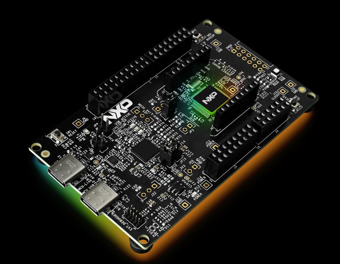
FRDM-MCX23 Board x 2
Personal Computer
Type C USB Cable x 2
Ammeter to measure current (Optional)
Software Requirements
IDE: Visual Studio Code 1.91.1
SDK: SDK v2.16.100 for FRDM-MCXW71
SPSDK Tool
Windows OS (It was used Windows 10 for this hands-on)
NXP IoT Toolbox (For Android or iOS device)
Hardware changes to measure current
In order to measure the current consumption in FRDM-MCX23 we have the following options:
Measure current in JP4. This will give you the overall consumption of the board, but this will not require hardware modifications.
Measure current in JP1. This is the current for peripheral circuits in the board. For this option JP1 must be populated and SH200 must be cut.
Measure current in JP2. This is the MCU current consumption. For this option JP2 must be populated and SH201 must be cut.
For this hand on we will measure current in JP2 to get the MCU consumptions in low power.
Note:
In order to make downloads in NXP website, it is necessary to have an account. Please, register and log-in for moving forward.
MCUXpresso for Visual Studio Code
MCUXpresso for Visual Studio Code (VS Code) provides an optimized embedded developer experience for code editing and development. The extension enables NXP developers to use one of the most popular embedded editor tools and provides an easy and fast way to create, build and debug applications based on MCUXpresso SDK or Zephyr projects.
Install it following the next steps:
Download Visual Studio Code from Microsoft Store or visual studio code web page Download Visual Studio Code - Mac, Linux, Windows
Access to vscode for MCUX wiki and download MCUXpresso Installer Dependency Installation · nxp-mcuxpresso/vscode-for-mcux Wiki · GitHub
Run MCUXpresso Installer and for this Hands On install at least
MCUXpresso SDK Developer
Arm GNU Toolchain
PEmicro
Installing the FRDM-MCXW23 SDK v 25.06.00.
Each MCU has its own SDK that includes driver, examples, middleware, docs and other components. To get and build the demo, let’s install the SDK into VS Code:
Once MCUXpresso for Visual Studio Code is installed open VS Code.
Go to MCUXpresso for VS Code extension that is on the tools column at the left.
Look for INSTALLED REPOSITORIES option and press ‘+’. Detail steps are described in
Use the steps for import a remote Git repository
wiki page. Working with MCUXpresso SDK · nxp-mcuxpresso/vscode-for-mcux Wiki · GitHub
Search for Revision v25.06.00 or newer and complete installation.
Installing SPSDK.
The SPSDK is a unified, reliable, and easy to use Python SDK library working across the NXP MCU portfolio providing a strong foundation from quick customer prototyping up to production deployment. The library allows the user to connect and communicate with the device, configure the device, prepare, download, and upload data including security operations.
Follow next steps for installation:
Create python virtual environment.
Open a Command Prompt window
Write python -m venv <name>
Active the virtual environment:
cd <name>
cd Scripts
activate
Make sure that your prompt starts with the selected “<name>”
Install SPSDK from Github into your Python virtual environment.
pip install -U spsdk
Wait until the installation is completed.
From now on you can use the virtual environment when it is needed, just open cmd open the Scripts or bin folder and write activate as in previous steps.
Make a Full flash erase using Blhost SPSDK.
Open SPSDK virtual environment
Open a command prompt
Change directory to open Scripts folder under SPSDK virtual environment
Write activate
Make sure your prompt starts with virtual environment name
Move command prompt to Virtual environment folder
Open Device Manager to check the MCU-Link COM
In your board set the jumpers JP13 and JP14 to connect pin 2 to 3.
Plug your board to your computers USB port, then press SW3, while keep pressing SW3 press Reset button (SW1) for a second, then make sure to release SW1 first, then release SW5.
Use Blhost command to make sure board communication is set up correctly a. >blhost -p comxx get-property 1
7. Use this Blhost command to erase your on-board flash b. >blhost -p comxx flash-erase-all
8. Restore JP13 and JP14 to connect to pin 1 to 2
Section 1. Run Low Power Reference Design
Open VS code
Go to MCUXpresso for VS Code extension that is on the tools column at the left.
Go to PROJECTS section and select “Import Example Application from and Installed Repository”
Select “frdmmcxw23_health_care_iot_peripheral_bm” project as in the next image and create the project
Repeat previous step for “frdmmcxw23_health_care_iot_central”
Go back to Projects view and build the projects clicking “Build Selected” icon
Connect USB cable to MCU-LINK (J10) connector on both boards
Open a Serial terminal on PC for the serial device with these settings on the two boards:
- 115200 baud rate
- No parity
- One stop bit
- No flow control
To identify the appropriate COM, open the Device Manager and look for MCU-Link VCom Port
9. Select “frdmmcxw23_health_car_iot_central” and click on debug to flash the code into one board
Click on “Continue” button or press “F5” key on your keyboard to continue running the downloaded program on device.
11. Click on “Stop” button or press “Shift + F5” to terminate the debug session.
12. Open a Serial terminal on PC for the serial device with these settings on the two boards:
- 460800 baud rate
- No parity
- One stop bit
- No flow control
To identify the appropriate COM, open the Device Manager and look for MCU-Link VCom Port
13. Repeat the steps from 9 to 11 with the "frdmmcxw23_health_care_iot_peripheral_bm" project into the second board
Clean serial terminals
Click SW1 button to reset the central board.
Click SW5 button to start the Health care IoT peripheral demo.
In the terminal you will see that the boards are communicating each other each second after the boards stablish connection.
Central Device
Peripheral Device
As expected the Peripheral device connects to the central device send the temp information. The peripheral device will keep advertising each second to report temperature and battery status, after this time it goes to Deep sleep mode.
The next step is to measure the current, connect the ammeter on JP2 in the peripheral device.
Figure 1 measuring an advertising interval
Figure 2 Board after pressing sw5
Figure 3 Board init services and start advertising until central scan connection
You can have more information about the Reference application Health Care IoT Central/Peripheral and how to modify the project to change adv interval or disable services on the application note: AN14659 MCX W23 Bluetooth Low Energy Power Consumption Analysis
View full article