Hands On
Goal of this lab is to show the SDK example implementing the wireless UART profile and we will move forward in making some meaningful modifications to the example itself with the goal to show where in the code the end user should enter the relevant application software for the application.
Hardware Requirements
Personal Computer
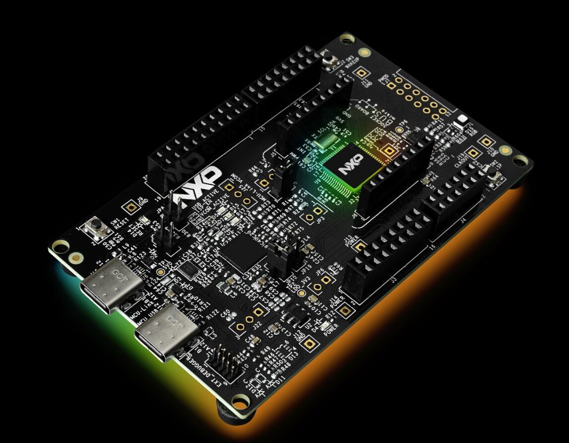
FRDM-MCXW23 Board
Type C USB Cable
Smartphone
Software Requirements
IDE: Visual Studio Code 1.91.1
SDK: SDK v2.16.100 for FRDM-MCXW23
SPSDK Tool
Windows OS (It was used Windows 10 for this hands-on)
NXP IoT Toolbox (For Android or iOS device)
Terminal program, like PuTTY or Tera Term
Note: In order to make downloads in NXP website, it is necessary to have an account. Please, register and log-in for moving forward.
MCUXpresso for Visual Studio Code
MCUXpresso for Visual Studio Code (VS Code) provides an optimized embedded developer experience for code editing and development. The extension enables NXP developers to use one of the most popular embedded editor tools and provides an easy and fast way to create, build and debug applications based on MCUXpresso SDK or Zephyr projects.
Install it following the next steps:
Download Visual Studio Code from Microsoft Store or visual studio code web page Download Visual Studio Code - Mac, Linux, Windows
Access to vscode for MCUX wiki and download MCUXpresso Installer Dependency Installation · nxp-mcuxpresso/vscode-for-mcux Wiki · GitHub
Run MCUXpresso Installer and for this Hands On install at least
MCUXpresso SDK Developer
Arm GNU Toolchain
PEmicro
Installing the FRDM-MCXW23 SDK v25.06.00.
Each MCU has its own SDK that includes driver, examples, middleware, docs and other components. To get and build the demo, let’s install the SDK into VS Code:
Once MCUXpresso for Visual Studio Code is installed open VS Code.
Go to MCUXpresso for VS Code extension that is on the tools column at the left.
Look for INSTALLED REPOSITORIES option and press ‘+’. Detail steps are described in
-Use the steps for import a remote Git repository
-wiki page.
4.Search for FRDM-MCXW23 v 25.06.00 SDK and complete installation.
Section 1. Wireless of simply less wires?
Open VS code
Go to MCUXpresso for VS Code extension that is on the tools column at the left.
Go to PROJECTS section and select “Import Example Application from and Installed Repository”
4.Select “frdmmcxw23_wireless_uart_bm” project as in the next image and create the project
5. Now you should have the “frdmmcxw23_wireless_uart_bm” in your workspace. Build the projects clicking “Build Selected” icon to make sure the build process succeeds with zero errors and warnings.
6. To make sure your board becomes “unique” we need to change the name of it as it appears in the BLE scanning process. To do this we need to modify a line of code in the app_config.c . In some SDK this file is only referenced from the SDK project. To avoid problems with the future projects we need to have selected the Freestanding option when importing the project.
In project explorer go to your project “frdmmcxw23_wireless_uart_bm” and open this explorer to find the “app_config.c” file.
Once opened, browse to line 76 and make the following modification
From
.aData = (uint8_t*)"NXP_WU"
to
.aData = (uint8_t*) "Custom_string"
IMPORTANT: Custom_string can be any string that is supposed to be unique in the class (your initials, name of your dog, anything meaningful to you only) Please note the string needs to be 7 characters maximum to avoid any other modifications in the code. In this Lab guide we will modify the string using “NXP_DT”
We will then do the following modification
.aData = (uint8_t*)"NXP_DT"
7. Verify that the modification succeeded by Building the project again and making sure you don’t get any error or warning.
8. Let us, at this point, get familiar with the board and the switches that we need to use to have the application running in the correct way.
The application makes use of two switches, the ROLESW-SW5 (Role Switch) and the SCANSW-SW2 (scan Switch), the establishment of a BLE connection is shown by the CONNLED (connection LED), please refer to the picture below to see where the switches and the LEDs are located on the FRDM-MCXW71 board.
9. Open a Serial terminal on PC for the serial device with these settings on the two boards:
115200 baud rate
No parity
One stop bit
No flow control
To identify the appropriate COM, open the Device Manager and look for MCU-Link VCom Port
10. We are now ready to start evaluating the example, Select “frdmmcxw23_wireless_uart_bm” and click on debug to flash the code into one board
11.Click on “Continue” button or press “F5” key on your keyboard to continue running the downloaded program on device.
You will immediately start noticing two things, the RGB LED (showing white color) and the BLUE LED on the board will start blinking at the same rate and you will see the “Wireless UART Starting as GAP Central” on the terminal.
12. The microcontroller is acting at this stage with the role that your smartphone is supposed to take in the example, to change the role click now the ROLESW=SW4 on the board to change the role to peripheral, the “switched role to GAP Peripheral” message on the terminal should be shown
13. It is now time to make the board visible to a Bluetooth scan, to do this press once the SCANSW=SW2 switch, you should notice now the RBG LED on the board stops blinking and only the CONNLED will continue. The “Advertising…” message should be now prompted on the terminal
14. It is time now to access the IoT Toolbox app on your smartphone and select Wireless UART
15. Once you click on “Wireless_UART” you should see a list of Wireless UART compatible devices advertising in that moment in the region around you (only the one under use at this stage in the picture below identified by NXP_DT)
16. If everything went correctly the BLE communication is in place, and you will observe the following three conditions:
A. The BLUE LED on the board becomes solid blue
B.The terminal will report the communication is in place by prompting “Connected to device 0 as peripheral”
C. The screen on your app will look like the following, please note the DICONNECT button at the top right of the screens that shows your smartphone is connected to the FRDM board
17. Type any character(s) into the text box on the IoT toolbox and press the Send button to wirelessly transmit character between the App and the MCXW71 device. Every character you will send from the app will be prompted on the console. At this point we have verified the basic way of working of the Wireless UART app that comes as part of the device’ s SDK.
Congratulations you have reached the end of the first part of the lab, you can now close the IoT Toolbox app on your smartphone and click on Terminate to stop debugging the application on the MCXW23 board.
18. It is now time to make some modifications on out of the box example to add additional interactions between the app and the board at hardware level, the goal is to become more familiar with the software stack in use and the available hardware resources.
As first step, we need to identify the right file where we will incorporate the modifications, the file we need to work on is called wireless_uart.c, same as with app_config.c this file is in the SDK folder so to avoid modifications on the SDK source we have to had imported the example as a freestanding application as show in the first parb of the lab. In window explorer go to your project “frdmmcxw23_wireless_uart_bm” and open the explorer to find the “wireless_uart.c” & “wireless_uart.h” files.
19. In the wireless_uart.c file we need to add the declarations, variables and includes to configure the LEDs commands. Let us start with the variables declarations, somewhere around line 267 (doesn’t really matter the exact number of the line you add the declaration on) add the following lines:
uint8_t command_uart;
uint8_t command_lenght;
20. We now need a more complex function to be declared to handle the LED’s behavior as well as the initialization of the ports and pins used, we will command the RGB LED located on the FRDM-MCXW23 board. In the Public functions section of the file (around line 271) place the following commandLed() function (use the copy_and_paste.txt file provided for this lab to avoid any formatting issues)
static void command_led(void)
{
if( (command_uart >= '0' && command_uart <= '4') && (command_lenght <= 2))
{
switch(command_uart)
{
case '0':
GPIO_PortClear(GPIO, 0U, 1<<0); //Turn on Green LED
GPIO_PortClear(GPIO, 0U, 1<<1); //Turn on Red LED
GPIO_PortClear(GPIO, 0U, 1<<4); //Turn on Blue LED
break;
case '1':
GPIO_PortSet(GPIO, 0U, 1<<0); //Turn off Green LED
GPIO_PortClear(GPIO, 0U, 1<<1); //Turn on Red LED
GPIO_PortSet(GPIO, 0U, 1<<4); //Turn off Blue LED
break;
case '2':
GPIO_PortClear(GPIO, 0U, 1<<0); //Turn on Green LED
GPIO_PortSet(GPIO, 0U, 1<<1); //Turn off Red LED
GPIO_PortSet(GPIO, 0U, 1<<4); //Turn off Blue LED
break;
case '3':
GPIO_PortSet(GPIO, 0U, 1<<0); //Turn off Green LED
GPIO_PortSet(GPIO, 0U, 1<<1); //Turn off Red LED
GPIO_PortClear(GPIO, 0U, 1<<4); //Turn on Blue LED
break;
case '4':
GPIO_PortSet(GPIO, 0U, 1<<0); //Turn off Green LED
GPIO_PortSet(GPIO, 0U, 1<<1); //Turn off Red LED
GPIO_PortSet(GPIO, 0U, 1<<4); //Turn off Blue LED
break;
default:
break;
}
}
}
21. To make use of the instructions that manipulate the GPIOs in the wireless_uart.c file we need to make sure they are reachable from the file itself, we ensure this with the following include statement which needs to be added in the include file section of the wireless_uart.c file (around line 30)
#include "fsl_gpio.h"
22. It is now necessary to call the above defined commandLed function in the whole BLE software flow, and, in particular it needs to be called in the BleApp_ReceivedUartStream function defined in the wireless_uart.c files somewhere around line 1440. Include then the commandLed() function just after the following line(s) of code (highlighted in yellow the function to be added and the position)
#if (defined(SERIAL_MANAGER_NON_BLOCKING_MODE) && (SERIAL_MANAGER_NON_BLOCKING_MODE > 0U))
serial_manager_status_t status = SerialManager_InstallTxCallback((serial_write_handle_t)s_writeHandle, Uart_TxCallBack, pBuffer);
(void)status;
assert(kStatus_SerialManager_Success == status);
(void)SerialManager_WriteNonBlocking((serial_write_handle_t)s_writeHandle, pBuffer, streamLength);
#endif /*SERIAL_MANAGER_NON_BLOCKING_MODE > 0U*/
}
command_led();
/* update the previous device ID */
previousDeviceId = peerDeviceId;
}
23. As last modification we need to ensure the commands sent by the user through the IoT toolkit App are correctly captured in the application. Locate the BleApp_GattServerCallback function in the wireless_uart.c file and add the two lines highlighted in yellow below considering the exact position in the code
static void BleApp_GattServerCallback
(
deviceId_t deviceId,
gattServerEvent_t *pServerEvent
)
{
uint16_t tempMtu = 0;
switch (pServerEvent->eventType)
{
case gEvtAttributeWrittenWithoutResponse_c:
{
if (pServerEvent->eventData.attributeWrittenEvent.handle == (uint16_t)value_uart_stream)
{
command_uart=*pServerEvent->eventData.attributeWrittenEvent.aValue;
command_lenght = pServerEvent->eventData.attributeWrittenEvent.cValueLength;
BleApp_ReceivedUartStream(deviceId, pServerEvent->eventData.attributeWrittenEvent.aValue,
pServerEvent->eventData.attributeWrittenEvent.cValueLength);
}
break;
}
case gEvtMtuChanged_c:
{
/* update stream length with minimum of new MTU */
(void)Gatt_GetMtu(deviceId, &tempMtu);
tempMtu = gAttMaxWriteDataSize_d(tempMtu);
mAppUartBufferSize = mAppUartBufferSize <= tempMtu ? mAppUartBufferSize : tempMtu;
}
break;
default:
{
; /* No action required */
}
break;
}
}
24. We are now done with the code modifications, let us repeat the steps we need to build, Debug and connect through the IoT Toolkit Wireless UART option to see if the modifications are working as expected. Once you are connected to the FRDM-MCXW23 board through the App you can enter, as done before, any character and it will be prompted back through the terminal, now, entering 1 will turn the RBG RED LED on, 2 will turn the RGB BLUE LED on, 3 will turn the RGB GREEN on, 0 will turn the RBG LED white and 4 will turn the RBG LED off.
NOTE: you can see from the code, in the commandLed() function that we are setting up and configuring the GPIOs every time the UART receives the characters, 1, 2, 3 or 0.
BONUS: Change the code and use/add other trigger commands. Change the LED colors you can showcase. Send messages though UART once a special character (or a combination of them) is received.
Congratulations, you have reached the end of the Wireless or simply less wires.
查看全文