
- Forums
- Product Forums
- General Purpose MicrocontrollersGeneral Purpose Microcontrollers
- i.MX Forumsi.MX Forums
- QorIQ Processing PlatformsQorIQ Processing Platforms
- Identification and SecurityIdentification and Security
- Power ManagementPower Management
- Wireless ConnectivityWireless Connectivity
- RFID / NFCRFID / NFC
- Advanced AnalogAdvanced Analog
- Neural Processing UnitsNeural Processing Units
- MCX Microcontrollers
- S32G
- S32K
- S32V
- MPC5xxx
- Other NXP Products
- S12 / MagniV Microcontrollers
- Powertrain and Electrification Analog Drivers
- Sensors
- Vybrid Processors
- Digital Signal Controllers
- 8-bit Microcontrollers
- ColdFire/68K Microcontrollers and Processors
- PowerQUICC Processors
- OSBDM and TBDML
- S32M
- S32Z/E
-
- Solution Forums
- Software Forums
- MCUXpresso Software and ToolsMCUXpresso Software and Tools
- CodeWarriorCodeWarrior
- MQX Software SolutionsMQX Software Solutions
- Model-Based Design Toolbox (MBDT)Model-Based Design Toolbox (MBDT)
- FreeMASTER
- eIQ Machine Learning Software
- Embedded Software and Tools Clinic
- S32 SDK
- S32 Design Studio
- GUI Guider
- Zephyr Project
- Voice Technology
- Application Software Packs
- Secure Provisioning SDK (SPSDK)
- Processor Expert Software
- Generative AI & LLMs
-
- Topics
- Mobile Robotics - Drones and RoversMobile Robotics - Drones and Rovers
- NXP Training ContentNXP Training Content
- University ProgramsUniversity Programs
- Rapid IoT
- NXP Designs
- SafeAssure-Community
- OSS Security & Maintenance
- Using Our Community
-
- Cloud Lab Forums
-
- Knowledge Bases
- ARM Microcontrollers
- i.MX Processors
- Identification and Security
- Model-Based Design Toolbox (MBDT)
- QorIQ Processing Platforms
- S32 Automotive Processing Platform
- Wireless Connectivity
- CodeWarrior
- MCUXpresso Suite of Software and Tools
- MQX Software Solutions
- RFID / NFC
- Advanced Analog
- Neural Processing Units
-
- NXP Tech Blogs
- Home
- :
- Model-Based Design Toolbox (MBDT)
- :
- Model-Based Design Toolbox (MBDT)
- :
- Module 5: V/F Scalar Control
Module 5: V/F Scalar Control
- Subscribe to RSS Feed
- Mark Topic as New
- Mark Topic as Read
- Float this Topic for Current User
- Bookmark
- Subscribe
- Mute
- Printer Friendly Page
Module 5: V/F Scalar Control
- Mark as New
- Bookmark
- Subscribe
- Mute
- Subscribe to RSS Feed
- Permalink
- Report Inappropriate Content
 |
INTRODUCTION
In this module of the 3-Phase PMSM Control Workshop with NXP's Model-Based Design Toolbox , we are going to spin the PMSM for the first time with S32K and MotorGD Development Kits, learn more about Model-Based Design approach by building a PMSM mathematical model in Simulink to facilitate the development and validation of control algorithm and ultimately deploy that algorithm on the real hardware and check the experimental results against the one obtained in simulation environment.
First, lets see what do we want to achieve in this module ?
- Check the PWM signals generation based on Space Vector Modulation (SVM) technique discussed in the previous module Module 4: Space Vector Modulation . More than that, we want to check the PWM signals under normal conditions and there is no better way to do that rather than having the motor spinning. By implementing a simple way to accelerate or decelerate the motor and maintain various speed levels based on the user commands received via serial communication from a host PC we can easily verify the SVM under both dynamic and steady-state regimes.
- Having the motor spinning in a steady-state regime will give us the possibility to implement, test and validate the phase currents measurement which is a critical mandatory step for Field Oriented Control (FOC). Because the phase currents are measured with shunt resistors mounted in series with the lower inverter switches we will need to synchronize the A/C conversions with PWM signals to obtain the meaningful values (...but more about that in the next module)
Based on these considerations, the simplest control method I can think off that allows us to achieve all these goals is: V/F Scalar Control. Another name for this method is Volts per Hertz (V/Hz) but the main principle behind it is the same: the ratio between voltage and frequency is kept constant throughout the motor speed range.
In Fig. 1, which represent the global application mapping diagram as discussed in Module 3: System Partitioning , are shown the main hardware blocks that are going to be configured and the control path we are going to follow (with red line). To achieve V/F scalar control we are going to configure the S32K FlexTimer peripheral to generate six PWM signals that are used to control the MotorGD Development Kit DC to AC power inverter via a dedicated MOSFET pre-driver chip: MC34GD3000. To enable the MC34GD3000 chip operation we will need to control two additional signals : Enable and Reset via dedicated GPIO.
The interactions between host PC and hardware will be done via OpenSDA serial communication that will be used to download the code generated from MATLAB and to visualize various control signals with FreeMASTER.
 |
| Fig. 1: Application Mapping - HW & SW modules used for V/F Scalar Control are highlighted in green |
After the control algorithm verification & validation but prior to connecting the PMSM Linix motor, we are going to check the PWM signals with an oscilloscope. This will ensure we are following all hardware recommendations and since we do not have yet active protections, it will spare us from unpleasant surprises.
V/F SCALAR CONTROL
If you recall the picture from Fig. 3, the 3-Phase PMSM Control Workshop with NXP's Model-Based Design Toolbox article, then you know that V/F Scalar Control is the term used to describe a very basic form of motor control that is using a non-vector approach scheme. A PMSM can be led to steady state regime by one of the following control techniques:
- simple voltage fed controller - like the one we are going to implement now.
- current type controller (DTC);
- speed controlled scheme (FOC);
To explain how this technique works lets recall first the Module 2: PMSM and FOC Theory . It that module we have discussed various reference frames used to describe the PMSM theory of operation and we have obtained the main equations of the motor in the shown here as (eq. 1 and eq. 2)
 |
(eq. 1) |
 |
(eq. 2) |
where:
 |
voltages and current in d-axis and q-axis respectively |
 |
d and q-axis inductances and stator winding resistance |
 |
d and q-axis flux linkage and permanent magnet flux linkage |
 |
electrical rotor speed |
Rewriting (eq.1) in scalar from and time domain we will obtain:
|
|
(eq. 3) |


In steady state regime, the flux linkage variation is zero, and for further simplification we are going to assume the stator winding resistance is neglectable. Taking into consideration these simplifications and the flux linkage equation (eq. 2) then the equations (eq. 3) becomes:
|
|
(eq. 4) |


At this point we can transform the electric speed in frequency and rewrite the (eq.4) as a ratio of V/F:
|
|
(eq. 5) |


In V/F scalar control method the frequency of the stator magnetic flux is set according with the desired synchronous rotor speed while the magnitude of the stator voltage is adjusted to keep the ratio between them constant. No control over voltage or current vectors angles is utilized, hence the name scalar control.
The V/F ratio is calculated from the nominal values of the PMSM voltage and frequency parameters. By maintaining a constant V/F ratio between the amplitude and frequency of 3-phase voltage waveforms, then the stator flux of the PMSM can be maintained relatively constant in steady state. However, in practice a typical V/F profile is not constant over the entire range of motor speed.
As can be seen in Fig. 2, the V/F profile may be divided in three main regions:
- Compensation – a higher than normal voltage is required to compensate the voltage drop across the stator resistance that was neglected for simplified mathematical model
- Linear - follows the constant V/f relationship as derived from (eq. 5)
- Field weakening - constant V/f ratio cannot be satisfied due to the stator voltages limitation at the rated value in order to avoid insulation breakdown
 |
| Fig. 2: V/F profile practical aspects |
The V/F scalar control is the most common control strategy used for induction motor drives. In case of PMSM, the V/F scalar control is a good alternative in applications where good dynamic performance is not required (e.g.: HVAC, fans, pumps or blowers). In such cases the V/F scalar control is performed without the need of a position/speed sensor.
By using V/F scalar control there is no need for high capability CPU as in the case of FOC, but keep in mind that this kind of simplicity also comes with some disadvantages:
- instability of the system after exceeding a certain applied frequency
- systems low dynamic performance, which limits the use of this control method
- poor fault protection against stall detection and over-currents
In case of PMSM, both open and closed-loop control of the speed can be implemented based on the V/F scalar control. Open-loop control is used in applications where system dynamic response is not a concern. For such use cases, the frequency is determined based on the desired speed and the assumption that the rotor will ultimately follow the synchronous speed.
Throughout this module we are going to implement an open-loop control system topology for a 3-phase PMSM using V/F scalar control as the one shown in Fig. 3. Such control structure will allow us to control the PMSM speed without any feedback of motor parameters or rotor position. The motor is driven by the conventional 3 phase voltage-source inverter via MotorGD DevKit. The NXP's S32K MCU is being used to generate the six PWM signals using a modified SVM PWM technique with 3-rd harmonic injection.
 |
| Fig. 3: V/F scalar control block diagram |
In order to maintain a similar topology with two control loops and similar data structures for the examples that we are going to use in this workshop, we are going to implement the V/F scalar control application based on:
- FAST control loop is executed at each 0.1ms and computes the PWM duty cycles based on Space Vector Modulation. The reference voltages for (dq)-axes and the motor electrical speed represent the inputs. The electrical angle needed for Inverse Park Transformation is computed based on electrical speed reference.
- SLOW control loop is executed at each 1ms and provides the voltage references for Inverse Park transformation and the electrical speed profile. Inside this loop, the user commands are handled and based on a parameterisable Ramp Profile the appropriate control parameters are generated. The V/F profile is implemented via a tunable Look-Up-Table (LUT)
MATLAB MODELLING OF CONTROL ALGORITHM
MATLAB/Simulink environment and NXP toolbox for S32K1xx allow us to approach the motor control algorithm development very straightforward. Using Model-Based Design strategy we can develop, implement, simulate and test the control method entirely in simulation environment and once we are satisfied with the results we can proceed further by deploying the generated code on the real target and perform final validation and testing.
Fig. 4 shows the Simulink model we are going to use for V/F scalar control implementation, testing and validation. The model can be find attached at the end of this article.
 |
| Fig. 4: Simulink model for the entire plant: MCU-DC2AC INVERTER-PMSM |
The model shown in Fig. 4 consists in three major subsystems that mimics the actual hardware arrangement, each one of them implementing a specific functionality:
- S32K14x EVB - implements the S32K MCU logic that allows the control algorithm to compute the PWM commands for the power inverter;
- Motor GD DevKit - implements a simplified model of power inverter that converts the PWM commands into high voltage continuous signals;
- PMSM Model - implements a simplified PMSM motor model that replicates the behavior for the real LINIX motor.
S32K14x EVB Subsystem
This is a discrete model that implements the V/F scalar control block diagram shown in Fig. 3. There are 2 subsystems that are triggered based on specific timing intervals. These 2 subsystem mimics the existance of the separated digital control loops: SLOW & FAST
 |
| Fig. 5: FAST and SLOW control loop model |
The SLOW Loop Subsystem Fig. 6, updates the commands for the FAST Loop Subsystem shown in Fig. 7. Based on the SPEED_CMD set by the user as motor target speed, a trapezoidal speed profile is generated using a dedicated Simulink block exposed by the AMMCLIB Add-on. Based on this SPEED_REF the electrical angle used for Inverse Park transformation is going to be derived.
 |
| Fig. 6: SLOW control loop model |
The quadrature voltages alpha-beta are computed based on the electrical angle and the (dq) reference voltages obtained in SLOW Loop. In case of UD_REF the value is set to 0 just to emulate the theory behind FOC and in case of UQ_REF the value is obtained from a Look-Up-Table (LUT) that implement the concept of V/F scalar control.
 |
| Fig. 7: FAST control loop model |
At each 0.1ms the PWM commands are computed and updated based on AMMCLIB specialized Simulink block that implements and optimized Space Vector Modulation with 3rd harmonic injection. These PWM commands are then passed to the next subsystem that emulates the operations for power inverter.
MotorGD DevKit Subsystem
This subsystem implements a basic model to emulate the DC2AC power inverter. The PWM commands are converted into high voltage signals (depending on the Vdc value selected) that are then applied to the motor windings.
 |
| Fig. 8: Simplified Power Inverter model |
PMSM Model Subsystem
The Simulink model consists in standard 3-phase PMSM motor equations shown in Module 2: PMSM and FOC Theory. Within the model you can easily identify:
- stator windings electrical model
- electro-mechanical model
- sinusoidal back-EMF model
 |
| Fig. 9: 3-phase PMSM model |
Note 1: we are not going into details about PMSM modelling since this is not the purpose of this module. Feel free to follow the link indicated in the model to get more details. As usual, if you have any questions about it, feel free to ask.
Note 2: I've choose to implement this simplified model to avoid the usage of other MATLAB toolboxes. If you have access to Simscape Power System you could use one of the motors from there.
MATLAB SIMULATION OF THE PLANT
The entire V/F scalar control algorithm (...and not only) can be validated using this simulation environment provided in MATLAB/Simulink. This way we can validate the Space Vector Modulation, V/f scalar control and PMSM motor dynamic responses even without having the actual hardware setup. For those of you planning to use NXP hardware in the future, this approach might be useful in getting familiar with motor control.
Fig. 10, 11 and 12 show the main control signals and outputs for each subsystems discussed earlier. At this point we can investigate various quantities that might not be easily accessible on the real plant.
 |
|
Fig. 10: V/F scalar control commands in case of start-up ramp: (1) Speed Profile, (2) Electric Angle, (3) quadrature voltage references and (4) 3-phase stator voltages references |
 |
| Fig. 11: Space Vector Modulation verification: Inputs & Outputs |
 |
|
Fig. 12: PMSM Model Responses in case of start-up sequence: (1) Command vs. Actual Motor Speed, (2) Rotor angle vs. Rotor position, (3) Stator Currents and (4) Back EMF voltages |
As can be seen there is a good match between the results obtained in simulation and the PMSM motor theory. Now that we have built confidence in the results it's time to move on to next stage.
EMBEDDED TARGET VERIFICATION OF CONTROL ALGORITHM
Since the modelling and simulation phases are completed with satisfactory results, it is time to convert the Simulink model and adapt it for Code Generation. The Fig. 13, shows the actual model that we are going to use the Code Generation.
 |
| Fig. 13: Simulink model for S32K embedded target code generation |
The model depicted in Fig. 13 is derived from the one shown in Fig. 4 and almost 90% of it share the same similarities. To have the model suitable for code generation there are a few modifications that needs to be done:
- Enable the MOSFET pre-driver;
- Enable the PWM signal generation from the appropriate FTM module;
- Add FreeMASTER communication driver into the application in order to have the capabilities to read/write data to/from S32K MCU;
- Remove the continuous blocks used in the previous simulation phase;
| Video training: Open Loop V/F Scalar Control Model for PMSM | ||
|---|---|---|
MC34GD3000 Pre-Driver Enablement
The MC34GD3000 is a field effect transistor (FET) pre-driver designed for 3-phase motor control and similar applications. The IC contains three high-side and three low-side FET pre-drivers. Three external bootstrap capacitors provide gate charge to the high side FETs. The IC interfaces to a S32K MCU via six direct input control signals, an SPI port for device setup and asynchronous reset, enable and interrupt signals. As it is shown in Fig. 14, the MC34GD3000 MOSFET pre-driver needs to be enabled before PWM signals generation.
The pre-driver can be configured over SPI communication to enable various features. Please check the MC34GD3000 for details. In this module we are not going to use this feature.
After IC initialization phase is complete, the device goes into the enable mode and operates normally. Normal operation continues in this mode as long as both enable pins EN1/EN2 and RSTB are high.
 |
| Fig. 14: MC34GD Pre-driver pins |
Add S32K dedicated peripheral blocks for GPIO to enable the MC34GD3000 pre-driver normal operation and remove the existing simplified simulation model blocks.
 |
 |
| Fig. 15: MotorGD subsystem: on the left - simplified inverter Simulink block diagram, on the right - S32K GPIO peripherals that set EN1/EN2 and RST pins to high | |
 |
 |
| Fig. 16: GPIO Configuration for Enable and RST signals | |
S32K FlexTimer(FTM) Enablement
The most important aspect of the whole application is to be able to generate the PWM signals based on the Space Vector Modulation technique and pass these signals to MC34GD3000 pre-driver. NXP's Model-Based Design Toolbox for S32K1xx address this issue in a very simple and convenient way by providing a S32K dedicated peripheral block for FTM as shown in Fig. 1
 |
 |
| Fig. 17: PWM generation in Simulink modelling vs. PWM generation used for code generation on S32K | |
The FTM Simulink block is configured to initialize the FTM3 module since the output signals from that specific module are routed on the PCB to control the actual power inverter MOSFETs. The schematic for the MotorGD DevKit Fig. 18, shows the actual signal routing.
The MotorGD DevKit was designed to be compatible with Arduino shields, therefore only some specific signals are available on the pin-headers. In case you design your own power inverter you might need to reconfigure the actual pins that controls the MOSFETs.
|
|
| Fig. 18: MC34GD3000 and MotorGD DevKit Power Inverter signal routing |

Based on the pins assignment on both MotorGD DevKit Fig. 19 and S32K14x EVB Fig. 20, we can configure the actual FTM peripheral as shown in Fig. 21.
 |
| Fig. 19: MotorGD DevKit Pin Assignment |
 |
| Fig. 20: S32K144 Evaluation Board Pin Assignment |
 |
 |
| Fig. 21: FTM Peripheral Block Configuration for controlling the power inverter from MotorGD DevKit | |
FreeMASTER Support for Data Visualization
Before generating the C-code for the application and deployment on the hardware, we need to enable and configure the FreeMASTER embedded driver to allow us the visualize the data in real time. Since most critical part of the V/F control algorithm is done in the FAST loop that is executed at each 0.1ms, we will need to configure the FreeMASTER to capture the data in that specific routine.
NXP's Model-Based Design Toolbox lets you configure and call the FreeMASTER anywhere in your model. For this application, since the goal is to check the real hardware data against the ones obtained from Simulink simulation we are going to configure the FreeMASTER as shown in Fig. 22.
 |
 |
| Fig. 22: FreeMASTER configuration | |
Please note that we have configured the FreeMASTER to work in Short Interrupt mode, with a relative high priority - less than the ones needed for actual motor control loops and we have enabled the Recorder option for a timebase of 0.1ms. All these settings and the actual function call for the FreeMASTER Recorder (Fig. 23) are needed to make sure you capture the data in the FAST loop - otherwise we might read wrong data.
 |
| Fig. 23: Place the FreeMASTER Recorder Call Simulink Block in the FAST Loop Sybsystem |
EMBEDDED TARGET VERIFICATION AGAINST SIMULINK SIMULATION
At this point we can run the application on the embedded side and verify the results against the ones obtained in simulation. Since we want to verify the algorithm behavior prior to running the actual motor, then for these kind of tests, we do not have to power on the MotorGD DevKit. This verification step can be done using PIL co-simulation as well but for getting closer to the final application setup, I've choose to run the application completely independent of MATLAB environment. In this case the real time data from S32K are obtained and visualized via FreeMASTER in RECORDER mode. The FreeMASTER project used in conjunction with Simulink model shown in Fig. 13 is attached at the end of the article.
First, we will check the correct generation of the commands for SVM and the PWM duty cycles waveforms associated with these commands. In the next figures, on the left hand side we can see the waveforms generated with MATLAB/Simulink environment in SIMULATION mode while on the right hand side the same data are RECORDED with FreeMASTER on real hardware S32K MCU for the same scenario. As you can see there is a remarkable similarities between these sets of data, giving us confidence that once the PMSM will be connected the motor will behave as predicted in SIMULATION environment.
 |
 |
|
Fig. 24: SIMULATION vs. REAL Start-up Sequence (1) Speed Reference Profile, (2)Electric Angle Transformation, (3) Fixed Frame Quadrature Voltages, (4) 3-phase PWM duty-cycles for each PMSM phase |
|
 |
 |
|
Fig. 25: SIMULATION vs. REAL Space Vector Modulation in Steady State Regime Inputs: (1) DQ Frame Voltages, (2) Fixed Frame Quadrature voltages, (3) Electric Angle for 500[rpm] equivalent Output: (4) SVM Sector Identification |
|
 |
 |
|
Fig. 26: SIMULATION vs. REAL PMSM Steady State Zoom (1) Electric angle variation for 500[rpm] motor speed and equivalent (2) SVM 3-phase voltage references |
|
VALIDATION ON REAL PLANT
Once the verification phase is completed successfully, we can start to validation on the real plant: MCU-DRIVER-PMSM
We start with PWM signal generation. The scope of this verification is to check the correct waveform generation (polarity and frequency) and signal integrity (rising/falling slopes, signal levels, dead-time). For this test we are going to use an oscilloscope to scope the digital signals directly on MotorGD DevKit PCB.
 |
|
| Fig. 27: PWM High (yellow) and Low (cyan) Commands |
Note PWM HIGH and LOW are configured to be complementary but due to HW restrictions the low side PWM signals are active LOW.
As can be seen in Fig. 27, the PWM signal generation is done correctly with 10KHz frequency and correct polarities based on the settings from Fig. 21.
At this point we can connect the PMSM and let is spin. If you power on the boards, the motor should start sniping, acceleration from 0 to 1000[rpm] in 1[sec]. From FreeMASTER watch variable window you can change the Speed_Command variable to increase and decrease the motor speed.
With the motor running, we can do some additional verification with the oscilloscope directly on the motor windings.
 |
|
| Fig. 28: Phase A &B terminal voltages and Line A-B resulting voltage. Check Module 4: Space Vector Modulation for details |
CONCLUSIONS
In V/F scalar control the stator currents are not controlled directly. A V/F controlled PMSM can become unstable easily especially when the load torque increases. Considering its disadvantages the V/F scalar control is not suitable for low speed control in high dynamic applications but might be a good choice for PMSM used for HVAC applications, where high performance is not required.
In general, open loop V/f control is not stable in the whole frequency range, it may become unstable, even at no-load, from a certain excitation frequencies lower than the rated speed. To address such use-cases, it is necessary to have a stabilizing loop in the system. This stabilizing loop can be implemented by means of an speed measurement system, increasing cost, and complexity.
At point we have reached our main goal and we now have a control simple method to spin the PMSM in open loop. We've validated the PWM generation techniques and we are now ready for the next step: implementing a proper Field Oriented Control technique for PMSM.
We hope you find this information useful. Feel free to LIKE this article and comment below.
Update January 28th 2019 - This Simulink model is now available on MATLAB 2018b and MBDT for S32K14x 2018.R1 release
Before using the new models make sure you apply all the hot-patches from here: HotFix: MBD Toolbox 2018.R1 for S32K
Update revisions:
March 18, 2019
- update the model to work with Model-Based Design Toolbox for MPC57xx Automotive Version 3.0.0 .
May 06, 2020
- update the model to work with Model-Based Design Toolbox for MPC57xx Automotive Version 3.2.0 .
- Mark as New
- Bookmark
- Subscribe
- Mute
- Subscribe to RSS Feed
- Permalink
- Report Inappropriate Content
Hi Daniel,
I try get eq3 from eq1, but the result seems should be as follows

the opertion sign before 3rd item is different from eq3, Am I wrong, or is there something wrong in eq1 or eq3 ? I'm fresh on PMSM theory. Could you pls confirm that? thanks.
- Mark as New
- Bookmark
- Subscribe
- Mute
- Subscribe to RSS Feed
- Permalink
- Report Inappropriate Content
Hi!
Could somebody say me what is "S_list" ?
kind regards
Francisco
- Mark as New
- Bookmark
- Subscribe
- Mute
- Subscribe to RSS Feed
- Permalink
- Report Inappropriate Content
Hi..In the simulation results, the stator phase currents are showing more than 2 A.(Nominal current is 2.3 A)
If I am not wrong, the simulation is done on NO LOAD. Then how come this much phase current is drawn?
Can anyone help me on this.
- Mark as New
- Bookmark
- Subscribe
- Mute
- Subscribe to RSS Feed
- Permalink
- Report Inappropriate Content
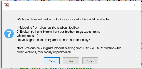
Hello all members, I am using MATLAB R2018b, Simulink 9.2 and MBDT v 4.2.0 but I am facing issues when I try to load the examples downloaded from below. (I am downloading M5_2018.R1.zip file how ever I also tried with M5.zip and still show similar error)
I will attach the screenshots so that it will be clear. I have also written my query in image itself.
errors_simulink_0.png shows the warning when I open the file provided at bottom.
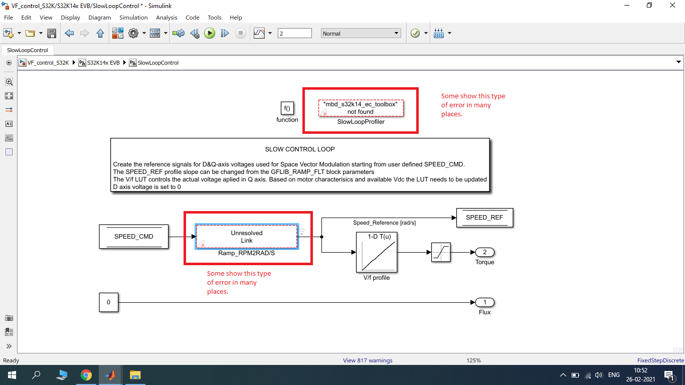
errors_simulink_1.png shows the two type of issues which I am facing.
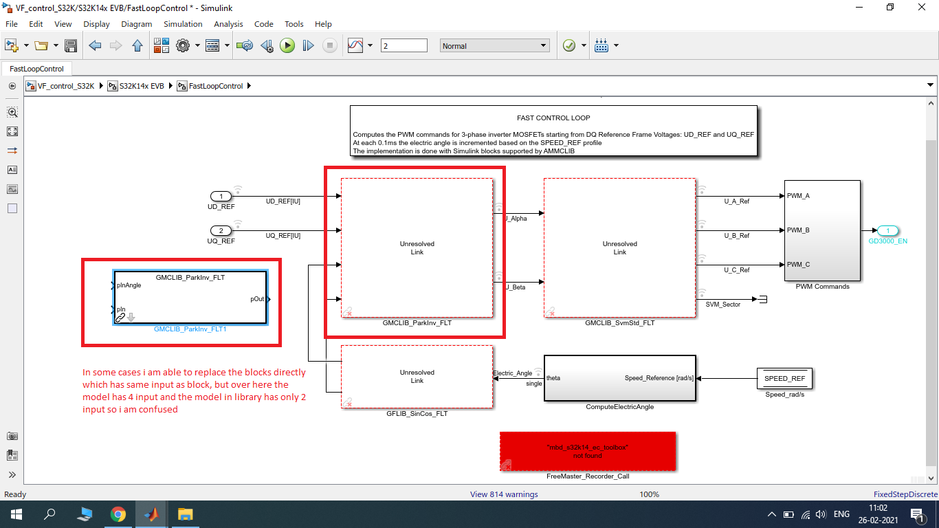
errors_simulink_2.png shows that I can replace some type of block but cannot replace other types.
Thanks and Regards,
RajG.
- Mark as New
- Bookmark
- Subscribe
- Mute
- Subscribe to RSS Feed
- Permalink
- Report Inappropriate Content
Hello there @Daniel_Popa and other community members , I am using MATLAB R2018b, Simulink 9.2 and MBDT v 4.2.0 but I am facing issues when I try to load the examples downloaded from below. (I am downloading M5_2018.R1.zip file how ever I also tried with M5.zip and still show similar error)
I will attach the screenshots so that it will be clear. I have also written my quires in image itself.
errors_simulink_0.png shows the waring when I open the file provided at bottom.
errors_simulink_1.png shows the two type of issues which I am facing.
errors_simulink_2.png shows that I can replace some type of block but cannot replace other types.
- Mark as New
- Bookmark
- Subscribe
- Mute
- Subscribe to RSS Feed
- Permalink
- Report Inappropriate Content
Hi again Daniel,
I'm having an issue building the code, that I haven't encounted before (i.e. other models build ok).
There's an error:
In file included from VF_control_S32K_b.c:17:0: VF_control_S32K_b.h:39:25: fatal error: tpp_ic_init.h: No such file or directory #include "tpp_ic_init.h" ^ compilation terminated. gmake: *** [VF_control_S32K_b.o] Error 1 ### Unable to find build success text: "*** Created executable:" in build log.
the h file is definitely in the toolbox path, so I'm not sure what's going on. Any ideas? Thanks
- Mark as New
- Bookmark
- Subscribe
- Mute
- Subscribe to RSS Feed
- Permalink
- Report Inappropriate Content
- Mark as New
- Bookmark
- Subscribe
- Mute
- Subscribe to RSS Feed
- Permalink
- Report Inappropriate Content
hello, Daniel
Would you please to explain why the inverter initializing sequence in Control_Logic will execute only once after the reset?
The Control_Logic is in the FastLoopControl subsystem, and it is invoked by function-call, so I think every time the FastLoopControl subsystem is invoked, the Control_Logic will be executed, which means the inverter initializing sequence will be executed.

- Mark as New
- Bookmark
- Subscribe
- Mute
- Subscribe to RSS Feed
- Permalink
- Report Inappropriate Content
Hi,
I have a question about the v/f profile LUT. The original data for the LUT is shown below.

I use excel to make these numbers more intuitive.

Since n_rpm = (30 * w_radpersec)/(pi * pp), so 209.4rad/s is equal to 30*209.4/(pi*2) = 1000rpm. And from the plot, it shows the rpm and uq_ref is linear.
From another perspective, the motor (model: 45ZWN24-40) has a rated voltage of 24V and rated speed of 4000rpm. Does it mean that if v/f scalar control method is used and 24V voltage is applied, then the speed will reach 4000rpm? If yes, does it mean the motor will reach 2000rpm when 12V voltage is applied?
What confuses me is that the model outputs 95% of the 12VDC voltage, however the reference speed is only 1000rpm. Should it be 1900rpm? Like the plot shown below.

- Mark as New
- Bookmark
- Subscribe
- Mute
- Subscribe to RSS Feed
- Permalink
- Report Inappropriate Content
Hello dumitru-daniel.popa,
Thank you for your note, I didn't notice the speed reference.
I updated the LUT, from Uq = 0.45 to Uq = 0.95 and speed from 0 to 1599 rpm.

My questions are:
- Why the motor doesn't feel anything under 0.45 Uq ?
- I noticed that the motor speed isn't smooth after 1599 rpm, Do you know why ?
- Why the Maximum phase voltage is Udc/2 (6 V not 12 V in my case) ?
- To reach rated speed, I need to increase the voltage to motor rated voltage and re-figure the LUT , right ?
Thank you.
- Mark as New
- Bookmark
- Subscribe
- Mute
- Subscribe to RSS Feed
- Permalink
- Report Inappropriate Content
Hi [email protected],
I'll try the best I can to explain, but keep in mind that some of my statements are assumptions based on my observations. So, here we go:
Why the motor doesn't feel anything under 0.45 Uq ?
We have about 10 motors in our storage, and I've noticed a variation in terms of mechanical and electrical parameters. I think this is an entry-level motor hence some variation is expected.
Furthermore, this is a 24V BLDC motor (the Back EMB is trapezoidal) and we are trying to control it as a PMSM with PWM sine-waves.
If you try to rotate the motor by hand, you will notice a high cogging torque. On top of that, I think there is also some friction that needs to be considered.
Nonetheless, I would expect to have it going with about 0.2Uq@12Vdc which is more or less in the ball parc of such methods.
I noticed that the motor speed isn't smooth after 1599 rpm, Do you know why ?
The motor rated speed is 4000rpm @ 24V (line-to-line). If we can only apply the maximum 12V(line-to-line) then it is safe to consider that we could achieve 2000rpm rated speed if the upper transistors are 100% open. In order to measure the phase currents we need some time to open the lower transistors hence the maximum duty cycle that we can push for with the upper transistors might be ~95% - hence the theoretical max speed decreases to 1900rpm.
Anyway, in closed-loop we are able to drive the motor up to 2000rpm and a bit above in no-load scenario, therefore, I presume the V/f characteristic might play a role in your case. Perhaps you need to make it a bit sharper at the end. Just monitor the Ud - if that increases towards the upper speeds domains, it means the rotor is losing the synchronism.
Typically, you need to consider that sqrt(ud^2+uq^2)<Vdc for stable control
Why the Maximum phase voltage is Udc/2 (6 V not 12 V in my case) ?
This might take longer to explain - but it is related to the 3-phase inverter theory of operation since you need to create +/- sine-wave. I think you will find the explanation in any power electronic book that describes the inverters. FYI, here is a quick link that I hope will help you clarify the context: https://subjects.ee.unsw.edu.au/elec9711/Section%207%20-%20Inverters.pdf
In the end, the line-to-line voltage will be 12V and this is what matters the most, this voltage drives the motor.
To reach rated speed, I need to increase the voltage to motor rated voltage and re-figure the LUT , right ?
I think so, please see the second answer. Keep in might to verify the Ud and Uq all the time. Ud should be kept at 0. Any voltage drop on D-axis means the rotor angle is not correct, the rotor is no longer aligned with the reference system and you start losing magnetic flux. Basically you are doing flux weakening, hence less torque, more chances to lose the synchronism.
Hope this helps!
Daniel
- Mark as New
- Bookmark
- Subscribe
- Mute
- Subscribe to RSS Feed
- Permalink
- Report Inappropriate Content
Hi dumitru-daniel.popa,
I manually put the UQ axis myself using freemaster and I noticed something.
the motor only start vibrating @ about 0.45 value, the motor rotates with vibration @ about 0.5 value.
I feel that the motor is loosing steps or PWM frequency is tool high or too low.
I linked a video with values from 0.45, 0.5, 0.6, 0.7, 0.8 and 0.9, the motor seems to be running but the noise is high and the rotation is not smooth.
I also attached the model and the freemaster project.
Regards.
- Mark as New
- Bookmark
- Subscribe
- Mute
- Subscribe to RSS Feed
- Permalink
- Report Inappropriate Content
Hi [email protected],
What is your speed reference for this video? I run a simple FFT on audio and seems like the final speed (at the end of the video is 250rpm ?)
If you feel that the rotor is not running synchronously with the reference speed, then perhaps you could try to modify that parameter also with FreeMASTER.
I would not play just with the UQ voltage but with both pairs (UQ, Reference Speed).
For example, in the beginning, the vibration might be caused by the low value of UQ vs higher value for the rotating angle.
Also, keep in mind that you may also experience torque oscillations due to the nature of the electro-mechanical system you what to control (just a reference to see how these vibrations depends on the type of PWM control and voltage levels http://itohserver01.nagaokaut.ac.jp/itohlab/paper/2016/20160918_ECCE/sato.pdf )
Nonetheless, towards the end of the video, I see the motor performs quite well. I think the noise comes from the fact that you put too much voltage 0.9PU at such low speeds.
Hope this helps!
Daniel
- Mark as New
- Bookmark
- Subscribe
- Mute
- Subscribe to RSS Feed
- Permalink
- Report Inappropriate Content
Hi dumitrupopadumitru-daniel.popa
I am running example M5 with library S12k14xx V3.
The code is building and flashing but the motor is vibrating continuously.
I got output on freemaster and it matches the simulation, but the motor is vibrating.
I am using 12V DC supply and a linux motor came with the kit.
Thanks.
- Mark as New
- Bookmark
- Subscribe
- Mute
- Subscribe to RSS Feed
- Permalink
- Report Inappropriate Content
Hi [email protected],
I'm not sure what
library S12k14xx V3
means ?
My advice is to take the latest version of the toolbox for S32K1xx Model-Based Design Toolbox for S32K1xx Automotive Version 4.1.0 and run the examples from ...\S32_Examples\s32k14x\mc\PMSM_Demo
The Linix motors might have small variations. The vibration can be addressed by changing the Look-up-Table parameters. Perhaps it is not enough current to start in an open-loop and the rotor synchronism is lost.
Hope this helps!
Daniel
- Mark as New
- Bookmark
- Subscribe
- Mute
- Subscribe to RSS Feed
- Permalink
- Report Inappropriate Content
Hi dumitru-daniel.popa,
Thank you for your response.
I have a question regarding the LUT, and please pair with me a bit :smileygrin:.

You said there are three regions (Compensation, Linear and Field weakening), How this is implemented on the LUT you added - cause I see it's a ramp and not like the image.
and from a theoretical way, how to determine the f_cutoff and f_nominal ? and Is the max F and V (of region three) are the maximum values of the motor ?
another point is to calculate the ratio V/F, Do I need to calculate the ratio based on Vmax and Fmax(speed max) or How to start on this ?
I hope I didn't ask too many questions :smileygrin:
Thanks.
- Mark as New
- Bookmark
- Subscribe
- Mute
- Subscribe to RSS Feed
- Permalink
- Report Inappropriate Content
Hello,
Can you please post the latest model compatible with latest library version ?
The demo images are different from what I have and some points are not described in the post - like spi configuration.
Thanks.
- Mark as New
- Bookmark
- Subscribe
- Mute
- Subscribe to RSS Feed
- Permalink
- Report Inappropriate Content
Hi [email protected],
A variation of this model - called PMSM Open Loop - is delivered with the MBDT Toolbox. You can find it in the ..\S32_Examples\s32k14x\mc\PMSM_Demo\PMSM_OpenLoop folder.
- Mark as New
- Bookmark
- Subscribe
- Mute
- Subscribe to RSS Feed
- Permalink
- Report Inappropriate Content
Hi,Daniel
the motor transfer function here is R/(Ls+1)
Is the actual value equivalent to 1/(Ls+R)?
best regards
hao
- Mark as New
- Bookmark
- Subscribe
- Mute
- Subscribe to RSS Feed
- Permalink
- Report Inappropriate Content


In FTM Configuration Why do you select PWM Pair 0-1(A) in independent mode and not in Complimentary Mode.
PWM signal to High side and Low side Mosfet Should be Complementary to each other. How Do you Producing Complementary Signal from Channel_0 and Channel_1?
How do you Introducing Deadtime between Mosfet Switching? beacause in FTM PWM Configuration you select Deadtime=0 ticks.
is there any relation of all this settings with PWM_LOGIC subsystem which contain Driver Initialization routine
can you please give detail of how do you generate Complementary signal with Dead time with reference to attached Model.
Regards
Aniket