
- Forums
- Product Forums
- General Purpose MicrocontrollersGeneral Purpose Microcontrollers
- i.MX Forumsi.MX Forums
- QorIQ Processing PlatformsQorIQ Processing Platforms
- Identification and SecurityIdentification and Security
- Power ManagementPower Management
- Wireless ConnectivityWireless Connectivity
- RFID / NFCRFID / NFC
- Advanced AnalogAdvanced Analog
- Neural Processing UnitsNeural Processing Units
- MCX Microcontrollers
- S32G
- S32K
- S32V
- MPC5xxx
- Other NXP Products
- S12 / MagniV Microcontrollers
- Powertrain and Electrification Analog Drivers
- Sensors
- Vybrid Processors
- Digital Signal Controllers
- 8-bit Microcontrollers
- ColdFire/68K Microcontrollers and Processors
- PowerQUICC Processors
- OSBDM and TBDML
- S32M
- S32Z/E
-
- Solution Forums
- Software Forums
- MCUXpresso Software and ToolsMCUXpresso Software and Tools
- CodeWarriorCodeWarrior
- MQX Software SolutionsMQX Software Solutions
- Model-Based Design Toolbox (MBDT)Model-Based Design Toolbox (MBDT)
- FreeMASTER
- eIQ Machine Learning Software
- Embedded Software and Tools Clinic
- S32 SDK
- S32 Design Studio
- GUI Guider
- Zephyr Project
- Voice Technology
- Application Software Packs
- Secure Provisioning SDK (SPSDK)
- Processor Expert Software
- Generative AI & LLMs
-
- Topics
- Mobile Robotics - Drones and RoversMobile Robotics - Drones and Rovers
- NXP Training ContentNXP Training Content
- University ProgramsUniversity Programs
- Rapid IoT
- NXP Designs
- SafeAssure-Community
- OSS Security & Maintenance
- Using Our Community
-
- Cloud Lab Forums
-
- Knowledge Bases
- ARM Microcontrollers
- i.MX Processors
- Identification and Security
- Model-Based Design Toolbox (MBDT)
- QorIQ Processing Platforms
- S32 Automotive Processing Platform
- Wireless Connectivity
- CodeWarrior
- MCUXpresso Suite of Software and Tools
- MQX Software Solutions
- RFID / NFC
- Advanced Analog
- Neural Processing Units
-
- NXP Tech Blogs
- Home
- :
- Model-Based Design Toolbox (MBDT)
- :
- Model-Based Design Toolbox (MBDT)
- :
- 3-Phase PMSM Control Workshop with NXP's Model-Based Design Toolbox
3-Phase PMSM Control Workshop with NXP's Model-Based Design Toolbox
- Subscribe to RSS Feed
- Mark Topic as New
- Mark Topic as Read
- Float this Topic for Current User
- Bookmark
- Subscribe
- Mute
- Printer Friendly Page
3-Phase PMSM Control Workshop with NXP's Model-Based Design Toolbox
- Mark as New
- Bookmark
- Subscribe
- Mute
- Subscribe to RSS Feed
- Permalink
- Report Inappropriate Content
 |
Design & Prototype Motor Control Applications with Model-Based Design Toolbox for S32K1xx |
INTRODUCTION
This is the Model-Based Design PMSM Workshops home page. The scope of this workshop is to familiarize readers with 3-phase PMSM control theory, NXP’s Automotive microprocessors designed for industrial control and provide prototyping implementation examples with Model-Based Design Toolbox.
This workshop is a medium to high complexity level but it does not require any prior knowledge of motor control, field oriented control or control system theory. All the important factors needed for a module completion will be presented as part of this workshop.
For demonstration we are going to use this NXP’s development kit platform. Anyhow, in order to avoid any hardware limitations we have designed the workshop’s examples to be generic so that you could use any other power stage inverters and/or PMSM motors.
MOTIVATION
Nowadays, our life without the means of transportation in various forms or the common indispensable household goods like washing machines, fridges or air conditioners is inconceivable. We are all living surrounded by things that one way or another are controlled via electric motors. The technology limits are pushed to extreme and the efficiency and price of solutions are stretched to limits.
Today’s applications require a large amount of integration across various subsystems such as electric motor, controlled supply source, control unit and wide range of sensors, which provide a conversion of electric energy to a specific mechanical movement.
Performing the mechanical movement according to certain specifications requires a suitable control strategy of the electric motor. The complexity of such control strategies requires deep knowledge of various engineering specializations: magnetic field theory, materials, mathematics, control systems and software development.
OBJECTIVES
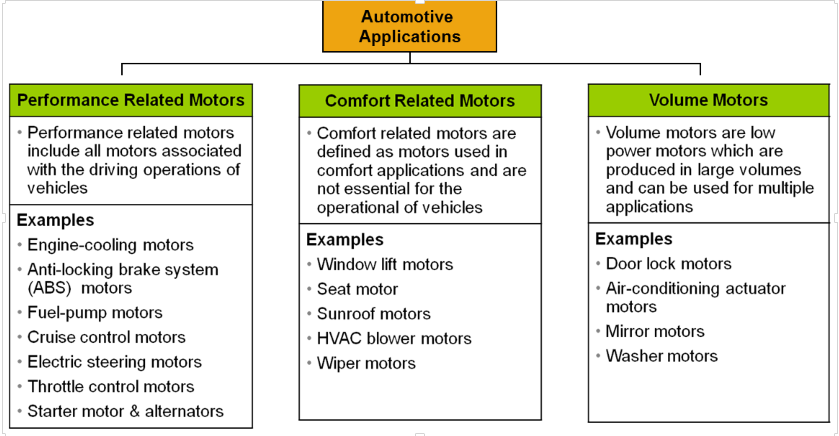
In this context, we are starting this workshop that will spread across the coming weeks. Considering the automotive industry, we are all witnesses to a growing demand for what is basically considered a motor controller subsystem. If we think about today & tomorrow cars we see a lot of applications that requires electric motors (a comprehensive article can be found here):
 |
| Fig. 1: Example of motor applications in a typical car - source: http://etn-demeter.eu |
The motor control techniques are quite complex and require knowing of controlled system parameters and control structure parameters. This is a matter of experience in the motor control theory which can cause difficulties to motor control developers or users. To avoid these problems and make the development of the motor control applications easier, we are starting this workshop with 4 main objectives:
 |
| Fig. 2: Workshop Objectives |
APPLICATIONS
Throughout the coming weeks we plan to tackle with Model-Based Design, four types of common PMSM motor control applications as depicted in the next figure.
 |
| Fig. 3: PMSM typical applications for motor control |
We are going thru prototyping from scratch using only MATLAB and Simulink, motor control applications for open and closed loop systems. We’ll discuss the theory behind every method, we will simulate and then test on the real hardware the Simulink models.
We shall start with a simple scalar control V/f to spin a motor and then based on this basic setup we are going to add PMSM phase current readings, close the current loop and finally build a closed loop speed control system. We shall pay special attention to FOC topics like Clarke and Park transformation, PI controller tuning, PMSM startup sequence and Position & Speed Estimation based on motor back-EMF observer.
METHODOLOGY
Due to subject complexity, we are going to use a mix of Community Articles and Community Videos to explain the concepts behind each topic. Each section will have a dedicated article with all the steps needed to fulfill a functionality and whenever is needed a brief video to explain the concept and/or to show that functionality in real time. All Simulink models and accompanying slides will be available for download.
If you are interested in this subject, please bookmark this page or click on Actions/Following In button to get periodic updates. As always, any suggestions for improvement and/or subjects are more than welcome!
WORKSHOP OUTLINE
This workshop is divided in 10 modules that will be released each week giving you plenty of time for interactions and clarifications. The plan of intend is shown below:
- Setting up the software: MBDT for S32K1xx, GCC and FreeMASTER
- Setting up the hardware: S32K144EVB evaluation board and Motor GD development kit
- Verify SW and HW setup: code generation, execution, real time data visualization
- PMSM Main Components and Mathematical Models
- BLDC vs PMSM Comparison
- Field Oriented Control
- Clarke and Park Transformations
- Field Oriented Control Stages
- FOC algorithm mapping over S32K1xx hardware
- Timings for slow and fast control loops
- Inputs/Outputs used for motor control
- Single phase modulation
- 3-Phase modulation
- 3rd harmonic injection
- PWM strategy
M5: V/f Scalar Control of PMSM
- Build a Simulink model to test SVM
- Build a Simulink model for the PMSM
- Test the model on SIMULATION and HARDWARE and compare the results
- Build an application spin the motor using V/F scalar control
- Current sensing techniques (dual-shunt method)
- System delays that affect the measurements
- PWM – PDB – ADC synchronization
- Current and Voltage scaling
- Real time measurements of phase currents and DC bus current and voltage
- Due to limitations in Jive platform the lecture comes in two parts:
Module 6: Current Sensing (Part 1/2)
Module 6: Current Sensing (Part 2/2)
- Close the current loop
- Tune current controller
- Implement PMSM start-up sequence
- Test application
- Implement a speed and position estimator based on hall sensor inputs
- Close the speed loop
- Tune the speed controller
- Test application under various conditions
- Design a back-EMF estimator
- Design a position tracking observer
- Mathematical model
- Compute parameters for back-EMF estimator and Tracking observer automatically
- Testing the position observer
- Due to limitations in Jive platform the lecture comes in two parts:
Module 9: Position Observer (Part 1/2)
Module 9: Position Observer (Part 2/2)
- Adapt startup-sequence to handle open to closed loop transitions
- Tune application
- Test application
- Mark as New
- Bookmark
- Subscribe
- Mute
- Subscribe to RSS Feed
- Permalink
- Report Inappropriate Content
Hello sir,
I can't find links for module 7,8 and 10. can someone help me ?
Thank you,
Ibrahim Eid
- Mark as New
- Bookmark
- Subscribe
- Mute
- Subscribe to RSS Feed
- Permalink
- Report Inappropriate Content
7#Module 7: Torque Control - NXP Community
8#Module 8: Speed Control - NXP Community
10#Module 10: Sensorless Speed Control - NXP Community
Hi, a bit late and I think you found it.
- Mark as New
- Bookmark
- Subscribe
- Mute
- Subscribe to RSS Feed
- Permalink
- Report Inappropriate Content
Hi ,Daniel
Now i am studying the demo CTU,
I am confusing the ADC commands in the CTU configuartion .

can you tell me how to Identify the difference between A and B ?
thank you very much.
best regards
hao
- Mark as New
- Bookmark
- Subscribe
- Mute
- Subscribe to RSS Feed
- Permalink
- Report Inappropriate Content
Hello [email protected],
I will try to respond to this question.
The CTU is able to start either a single conversion or dual conversion.
In Single Conversion, the CTU triggers the Channel for selected port 6 from the ADC Port B.

In Dual Conversion, the CTU can trigger two channels from different ADC peripherals. In this case channel 0 from ADCA and Channel 0 from ADCB. Obviously the ADC peripherals should be configured as in the ADC Config example block.

In order to identify which is the ADC Port A and ADC Port B for each CTU peripheral, you can consult the following diagram: basically the CTU0 can control the ADC0 (Port A) and ADC1(Port B) while the CTU1 can control the ADC2 (Port A) and ADC3 (Port B).

For more details, you can consult the Chapter 35: ADC Configuration from the MPC5744P Reference Manual https://www.nxp.com/webapp/Download?colCode=MPC5744PRM.
Hope this helps,
Marius
- Mark as New
- Bookmark
- Subscribe
- Mute
- Subscribe to RSS Feed
- Permalink
- Report Inappropriate Content
hi ,Marius
thank you very much for replaying,
that is very helpful for me.
have a nice day,
best regards
hao
- Mark as New
- Bookmark
- Subscribe
- Mute
- Subscribe to RSS Feed
- Permalink
- Report Inappropriate Content
- Mark as New
- Bookmark
- Subscribe
- Mute
- Subscribe to RSS Feed
- Permalink
- Report Inappropriate Content
HI [email protected],
I am sorry, but I can not give an answer about the Lesson 10. Maybe dumitru-daniel.popa can.
Best Regards,
Marius
- Mark as New
- Bookmark
- Subscribe
- Mute
- Subscribe to RSS Feed
- Permalink
- Report Inappropriate Content
Dear sir,
When is Lesson 10?
I expect.
Best regards、
- Mark as New
- Bookmark
- Subscribe
- Mute
- Subscribe to RSS Feed
- Permalink
- Report Inappropriate Content
- Mark as New
- Bookmark
- Subscribe
- Mute
- Subscribe to RSS Feed
- Permalink
- Report Inappropriate Content
Is this lecture applicable for MTRCKTSPS5744p motor kit? Thanks.
- Mark as New
- Bookmark
- Subscribe
- Mute
- Subscribe to RSS Feed
- Permalink
- Report Inappropriate Content
Hello jimduanva,
Thank you for your interest in using MBDT.
First of all please have a look on our MPC574xP - Tutorials which are made with the Low-Cost Motor Control Solution for DEVKIT Platform|NXP.
For your answer, I don't have a clear one but as far as I understand from the documentation, the difference between the MPC5744P 3-phase PMSM Development Kit|NXP and the one from the tutorials is that the board you want to use has a MC33937: 3 Phase Field Effect Transistor Pre-driver while the Devkit platform uses a GD3000 3-Phase Brushless Motor Pre-Driver|NXP. The initialization looks to be similar, both kits usese MPC5744P mcu, so the same functionality can be achieved but only after the project is migrated to the setup you want and here I am refering at the pins and peripherals used. So before the model is compiled you need to line up the model to the schematics of the kit you are interested in.
Hope this help,
Marius
- Mark as New
- Bookmark
- Subscribe
- Mute
- Subscribe to RSS Feed
- Permalink
- Report Inappropriate Content
Hi Dumitru-Daniel,
when follow M9: Rotor Position Estimation and M10: FOC – Sensorless Speed Control?
Best regards
Dieter
- Mark as New
- Bookmark
- Subscribe
- Mute
- Subscribe to RSS Feed
- Permalink
- Report Inappropriate Content
Hi Dieter,
M9 will become available soon. https://community.nxp.com/thread/475657#comment-1014022
My target: Monday June 4th
Thank you!
Daniel
- Mark as New
- Bookmark
- Subscribe
- Mute
- Subscribe to RSS Feed
- Permalink
- Report Inappropriate Content
I'm looking forward to view upcoming videos in this series!
I have one request/suggestion:
can You elaborate more on the topics of tuning current and speed controller loops ?
Maybe show us a few practical methods, not just one...
What about applications when we can't tune controllers at factory level and the tuning must be done in the field ?
Can You show us (or at least mention) some good strategies for implementing automatic tuning in such cases ?
Best regards
Maciek
- Mark as New
- Bookmark
- Subscribe
- Mute
- Subscribe to RSS Feed
- Permalink
- Report Inappropriate Content
Hi Maciek,
Thank you for your feedback. By default i'll try to cover the mathematical approach for tuning the controller parameters but will also try to mention others.
Indeed - that might not always work since taking into consideration all the factors that influence the current/speed loop is not always practical. I think the mathematical approach is always a first step since it place the controller gains in the ballpark - at least you have something to start with. Then - you have to do some fine manual tuning following some simple rules (i will try to discuss that as well based on my practical experience in the industry)
What about applications when we can't tune controllers at factory level and the tuning must be done in the field ?
In fact we have a tool like that called Motor Control Application Tunning (MCAT) which is part of the reference applications: S32K144 3-phase PMSM Development Kit|NXP . That might be a solution for tuning.

Can You show us (or at least mention) some good strategies for implementing automatic tuning in such cases ?
I personally used 2 methods - both of them quite reliable:
#1: measure directly system resistance&inductance and inertia&friction. This requires some special testing development routines. Base on these value measured, we can then compute the controller gains with simple pole placements or Ziegler-Nichols methods.
#2: system closed loop transfer function identification with white noise injection. First we inject an white noice as voltage command and we measure the current responses - and then we estimate the current loop transfer function.
With the current controller tuned - then we inject a white noise as current and measure the speed/position responses - and then we have the speed transfer function.
We can use these 2 transfer functions to tune the controllers for both slow and fast loops. Of course the second method is more complex.
What else have you used ?
Looking forward for your feedback.