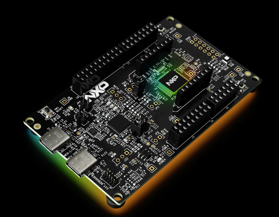
FRDM Training Hub

取消
显示结果 
显示  仅  | 搜索替代 
您的意思是: 

FRDM Training Hub

FRDM Training Hub


Restricted Beta Program

  • Comprehensive software and tools for seamless prototyping and rapid development
  • Scale your project with modular, quick-start FRDM and expansion boards
  • Leverage our application code hub or GoPoint to access 180+ code snippets and demos

  • Leverage FRDM Training Hub to learn from the experts
  • Not sure where to start ?

讨论

排序依据:
  Introduction   This hands-on walks you through everything that happens before you ever write a line of application code: unboxing your FRDM i.MX 95 Pro board, getting acquainted with its layout and ports, powering it on, and confirming a healthy first boot from the on-board eMMC. By the time you are done, you will be comfortable using both the i.MX System Manager console and the Linux command line to confirm exactly what hardware you have in front of you. By the end you will be able to: Verify that the contents of your FRDM i.MX 95 Pro box are complete Get acquainted with the board, its peripherals, and ports Set up and boot the board for the first time Get familiar with the i.MX System Manager (SM) console and the Linux CLI Verify the board's hardware and resources using Linux commands Hardware & Prerequisites You need very little to get started: FRDM-IMX95-PRO board (the box) — in addition to the board itself, the box includes USB-C cables for power and debugging, mounting standoffs, the IW612 wireless module, and a documentation card linking to the product page and a getting-started tutorial. Power supply — a USB-C to USB-C cable is included in the box. For basic bring-up, any standard USB-C phone charger is sufficient. If your setup adds higher-power accessories (e.g., a display), use a 100 W-capable USB-C power adapter instead. PC host — a computer with a terminal / serial console program to connect to the board's debug port. That's it — no display or camera is required for this hands-on. Watch the Module Video Watch the full hands-on walkthrough below, then follow along on your own board.   Steps to Run the Hands-On Step 1: Explore the Board with Linux Commands Once the board has booted, open a terminal on the debug console and run the following commands to confirm the Linux environment and the hardware resources available to you. # 1) Linux version uname -a # 2) Storage devices lsblk # 3) Verify CPU numbers and architecture. lscpu # 4) SoC Id and Family cat /sys/devices/soc0/soc_id cat /sys/devices/soc0/family # 5) RAM memory available cat /proc/meminfo | head -20 # 6) network peripherals and addresses ip addr # 7) List Video Encoders and Decoders v4l2-ctl --list-devices # 8) GPU specs and capabilities vulkaninfo --summary # 9) Print available GPIOs gpioinfo Step 2: Explore the i.MX System Manager Console Next, switch to the i.MX System Manager (SM) console to inspect the board at the system level — Logical Machines, boot times, power rails, and clocks. # 1) System manager version, Board, Revision, Silicon etc info # 2) Logical Machines information lm info # 3) Boot time of each Logical machine btime # 4) Power status of each peripheral power.r # 5) Clocks status clock.r Troubleshooting Symptom What to check Power LED is on but there is no output on the console Check the Boot Mode switches (set them to eMMC) Power-cycle the board (turn it off and back on) after changing the Boot Mode switches Verify the serial console baud rate is set to 115200 Confirm the Debug port is connected to the host PC Open all the COM ports exposed by the board when the Debug port is connected to the host PC Conclusion In this hands-on, you: Verified the contents of your FRDM i.MX 95 Pro box Got acquainted with the board, its peripherals, and ports Set up and booted the board for the first time from eMMC Used the i.MX System Manager console and the Linux CLI to inspect the board Confirmed the board's hardware and resources via Linux commands If you have not already, watch the module video above for the full walkthrough, and check out the rest of the FRDM Training Hub for the next hands-on in the series.
查看全文
  Introduction This hands-on walks you through bringing a display to life on the FRDM-IMX95-PRO board. You will flash a BSP image to an SD card, attach a Waveshare 7" DSI LCD, select the correct device tree in U-Boot, and then exercise the panel with brightness control, screen rotation, capacitive touch, and a live camera video pipeline. By the end you will have a fully working touch display and the core skills to configure DSI panels on i.MX 95. By the end of this hands-on you will be able to: Flash a BSP image to a microSD card using UUU in Serial Download mode. Connect the Waveshare 7" DSI display (FPC, power, and I2C) correctly. Select the matching device tree for the panel from the U-Boot prompt. Adjust and script the display backlight brightness. Rotate the screen through Weston's configuration. Verify capacitive touch with evtest . Stream live camera video to the panel with GStreamer. Hardware & Prerequisites FRDM-IMX95-PRO board. MicroSD card — 16 GB or larger. Waveshare 7" DSI LCD — 1024×600 IPS, 5-point capacitive touch. 22-pin FPC cable. Host PC with UUU installed. Watch the Module Video Watch the full hands-on walkthrough first to see each step performed on real hardware, then follow along on your own board using the steps below. Steps to Run the Hands-On 1. Enter Serial Download Mode Put the board into Serial Download Protocol (SDP) mode so the host can push the image, then connect it to your PC: Set boot switch SW1 = 1000 (Serial Download Protocol mode). Connect J7 USB-C to the host PC. Connect J22 USB-C to view debug output on the serial console. 2. Flash the BSP Image with UUU Run the following command on your host computer to flash the BSP boot image and full image to the SD card: # --- UUU --- # Run the following command on your host computer uuu.exe –b sd_all imx-boot-imx95-19x19-lpddr5-frdm-pro-sd.bin-flash_a55 imx-image-full-imx95evk.wic.zst 3. Switch to SD Boot Once flashing completes, reconfigure the board to boot from the SD card: Power off the board. Set boot switches SW3 and SW4 = 0011 (SD card boot). Turn on the board. 4. Connect the Display — FPC Cable Attach the 22-pin FPC cable between the board and the Waveshare panel, paying close attention to cable orientation on each end: Connect the 22-pin FPC to the board's MIPI-DSI connector — the stiffener side faces the board connector. Connect the other end to the Waveshare panel (15-pin side) — the conductive side faces the panel. 5. Connect the Display — Power & I2C The panel needs both power and an I2C connection for the display output to come up: Connect I2C via the J6 4-pin header. Connect 5V power to J17 (or any 5V connector). I2C must be connected for display output to work. 6. Change the Device Tree in U-Boot Watch the serial console during boot and press any key at the U-Boot countdown to reach the prompt: Hit any key to stop autoboot: 3 => (U-Boot prompt) At the U-Boot prompt, select the device tree for the Waveshare panel and boot: # --- U-Boot: select the device tree for the display --- fatls mmc 1 setenv fdtfile imx95-19x19-frdm-pro-waveshare-7inch-c-panel.dtb saveenv boot 7. Set & Check Backlight Brightness Once Linux is running on the board, the panel backlight is exposed through sysfs. The commands below set a brightness value and read the current and maximum allowed values. Valid range is 0 (off) up to max_brightness . Run these as root: # --- Linux on board --- # Run the following command on the board # Path to the backlight /sys/class/backlight/3-0045/ # Set brightness echo 128 > /sys/class/backlight/3-0045/brightness # Read the current value cat /sys/class/backlight/3-0045/brightness # Read the maximum allowed value cat /sys/class/backlight/3-0045/max_brightness 8. Fun Example — Breathing Backlight For a quick visual test, this small script ramps the backlight up and down continuously, giving a "breathing" effect. Save it as breathe.sh , make it executable, and run it as root. Press Ctrl+C to stop. # --- Linux --- # Breathing back light # Create and open the file vi breathe.sh # Write the following lines into the bash script BL=/sys/class/backlight/3-0045 MAX=$(cat "$BL/max_brightness") while true; do for ((i=0; i<=MAX; i++)); do echo "$i" > "$BL/brightness"; sleep 0.01; done for ((i=MAX; i>=0; i--)); do echo "$i" > "$BL/brightness"; sleep 0.01; done done # Change the permissions of the bash script chmod +x breathe.sh # Run the bash script ./breathe.sh 9. Rotate the Screen (Weston) Display orientation is controlled in Weston's configuration file. Edit weston.ini , add an [output] section with the desired transform, then restart the service: # --- Linux --- # On board # File path /etc/xdg/weston/weston.ini # Open the file vi /etc/xdg/weston/weston.ini # Add the following [output] name=DPI-1 transform=rotate-90 # Valid formats # normal - 0 degrees (default) # rotate-90 - 90 degrees clockwise # rotate-180 - upside down # rotate-270 - 270 degrees clockwise # Reboot or restart the service systemctl restart Weston # Check the status of the service systemctl status weston You can confirm the panel resolution and active modes with modetest : # --- Linux --- # Check the panel resolution modetest -c # list connectors & modes # full DRM/KMS overview modetest # Look for the DSI/DPI connector and confirm # 1024x600 is listed as an active mode 10. Test Capacitive Touch (evtest) Run evtest with no arguments to list the available input devices, then select the touch screen's event number to start capturing touch events: # --- Linux --- # Touch screen evtest # Run the evtest command evtest # It will list the available devices Available devices: /dev/input/event0: scmi_dev.11 /dev/input/event1: Goodix Capacitive TouchScreen Select the device event number [0-1]: 1 # Then it will run the evtest of the touch screen 11. Display Camera Video (GStreamer) Stream live camera video to the panel to verify both the camera and the display path in one go: # --- Linux --- # Gstreamer pipe line for webcam # Run the following command gst-launch-1.0 v4l2src device=/dev/video52 ! video/x-raw,width=640,height=480 ! Glimagesink # Pipeline breakdown # v4l2src device=/dev/video52 - capture from V4L2 node # video/x-raw,width=640,height=480 - raw 640x480 video # glimagesink - render on display via OpenGL Troubleshooting Symptom What to check No display output Check FPC orientation — the stiffener side must face the board connector. Ensure the I2C bus (J6) is connected; it is required for display output. fatls mmc 1 fails Verify the SD card is inserted. Confirm SW3 and SW4 = 0011 (SD boot mode). "No such file or directory" at the backlight path Confirm the node name with ls /sys/class/backlight/ . Touch not working after screen rotation Add a calibration_matrix for the touch device in weston.ini , or configure the touch coordinate transform via libinput. Conclusion In this hands-on you brought up a Waveshare 7" DSI display on the FRDM-IMX95-PRO board from a fresh SD card flash all the way to a working touch panel with live camera video. Key takeaways: Flashed a BSP image to the SD card with UUU and switched the board to SD boot. Connected the DSI panel correctly (FPC orientation, 5V power, and the required I2C link). Selected the matching device tree in U-Boot so the panel enumerates at 1024×600. Controlled backlight brightness, rotated the display in Weston, validated touch with evtest , and verified the camera path with GStreamer. Be sure to watch the module video above to see each step in action, and explore the rest of the FRDM-IMX95-PRO Training Hub for more hands-on modules.
查看全文
  FRDM i.MX 95 Pro · Hands-On Series GoPoint — Running Pre-Built Demos September 2026  |  FRDM i.MX 95 Pro Hands-On Series   Introduction Discover what your FRDM i.MX 95 Pro can do — right out of the box. This hands-on walks you through the full range of pre-built demo categories available through GoPoint on the FRDM i.MX 95 Pro board. From neural processing and machine learning to GPU-accelerated graphics, each demo showcases the real-world capabilities of NXP's i.MX 95 application processor — no custom code required. The hands-on covers the following topics: Launching GoPoint on the Weston desktop Exploring the available demo categories (NPU, ML, GPU) Running NPU demos with the Ara240 module Running ML and GPU demos By the end of this hands-on, you will be able to: Navigate the GoPoint interface on Weston Identify the available demo categories (NPU, ML, and GPU) Launch and run pre-built demos on your FRDM i.MX 95 Pro board Understand the hardware requirements for each demo type   Hardware & Prerequisites Before starting, make sure you have the following items ready: Required Hardware FRDM-IMX95-PRO board (booted from eMMC) HDMI display Mouse Keyboard USB camera Ara240 module (required for NPU demos) Optional Hardware EXPI-OS08A20 camera module — covered in the separate EXPI-OS08A20 Camera + ISP Pipeline hands-on Note: The board must be booted from eMMC with the pre-loaded BSP image before launching GoPoint. Ensure your display is connected via HDMI before powering on.   Watch the Hands-On Video A complete video walkthrough accompanies this hands-on. It demonstrates every step shown below — from opening GoPoint on Weston to running NPU, ML, and GPU demos live on the board. Watch it alongside the written steps for the best learning experience.   Steps to Run the Hands-On Follow the steps below to explore GoPoint and run the pre-built demos on your board. Step 1 — Launch GoPoint on Weston After the board boots into the Weston desktop environment, locate the GoPoint application icon on the desktop or in the application launcher. Click it to open the GoPoint demo browser. GoPoint provides a graphical interface that organises all available demos by category, making it easy to browse and launch them without any command-line interaction. Step 2 — Explore the Demo Categories Once GoPoint is open, you will see the main demo category tiles. The three primary categories available on the FRDM i.MX 95 Pro are: NPU Demos — Neural Processing Unit demos that leverage the Ara240 module for hardware-accelerated AI inference ML Demos — Machine learning demos running on the i.MX 95 application processor GPU Demos — Graphics Processing Unit demos showcasing GPU-accelerated rendering and compute Browse each category to see the individual demos available. Each demo tile shows its name, a brief description, and any special hardware it requires. Step 3 — Run NPU Demos (Ara240 Required) NPU demos require the Ara240 module to be attached to the board. Select any NPU demo from the GoPoint interface and click Run. GoPoint will automatically load the required AI model and launch the demo. The Ara240 module handles the neural network inference, delivering real-time results on-screen. Note: If AI/ML models are not yet present on the board, run the fetch_models command first (see the Troubleshooting section below). Step 4 — Run ML Demos ML demos run directly on the i.MX 95 application processor and do not require the Ara240 module. Select an ML demo from the GoPoint interface and click Run. These demos cover a range of machine learning use cases including image classification, object detection, and more. Step 5 — Run GPU Demos GPU demos showcase the graphics and compute capabilities of the i.MX 95's integrated GPU. Select a GPU demo from the GoPoint interface and click Run. These demos include GPU-accelerated graphics rendering and visual effects that highlight the board's multimedia performance.   Troubleshooting If you encounter issues while running GoPoint demos, use the table below to identify the symptom and the recommended action. Symptom What to Check Missing AI/ML models — demo fails to start or reports missing model files Fetch the required models using the commands below. Use --list to see available models and --repo-id to fetch a specific one: # List available models fetch_models --list # Fetch a specific model by repository ID fetch_models --repo-id Cannot download software requirements — network or SSL errors during model download The board's system clock may be incorrect, causing certificate validation to fail. Set the correct date and time, then retry: # Set the system date (replace with current date/time) date -s "MM/DD/YYYY HH:MM:SS" Board freeze — the board becomes unresponsive during a demo Reboot the board: reboot Corrupt download — a demo crashes immediately or shows unexpected errors after model download Remove the Python virtual environment ( venv ) for the affected demo and re-run it so GoPoint recreates a clean environment. The venv directory is located inside the demo's working folder. # Remove the venv of the corresponding demo, then relaunch it from GoPoint   Conclusion In this hands-on you explored the GoPoint application on the FRDM i.MX 95 Pro board and ran pre-built demos across three hardware-accelerated categories: Launched and navigated the GoPoint interface on the Weston desktop Ran NPU demos using the Ara240 neural processing module Ran ML demos on the i.MX 95 application processor Ran GPU demos showcasing the board's graphics capabilities Learned how to fetch AI/ML models and resolve common setup issues For a full visual walkthrough, watch the video in the Watch the Hands-On Video section above. To continue your learning journey, visit the FRDM i.MX 95 Pro Training Hub for the complete series of hands-on modules covering camera pipelines, connectivity, security, and more.
查看全文
FRDM i.MX 95 Pro Hands-On: ARA240 DNPU AI Accelerator FRDM i.MX 95 Pro Hands-On Training Series  |  September 2026   Introduction This hands-on walks you through the ARA240 DNPU AI Accelerator integrated with the FRDM i.MX 95 Pro development board. The ARA240 is an M.2-form-factor neural processing unit that connects over PCIe and dramatically expands the board's AI inference capability — from classic computer-vision pipelines to large language models (LLMs) and vision-language models (VLMs) — all powered by NXP's eIQ software stack.   Item Details Host Board FRDM i.MX 95 Pro AI Accelerator ARA240 DNPU (up to 2 modules) BSP L6.18.20-2.0.0 (precompiled, available on the NXP website) Interface PCIe via M.2 Key-M slots J24 / J25   By the end of this hands-on you will be able to: Verify that the ARA240 DNPU is correctly detected by the system. List, download, and run AI models (CNN, LLM, VLM) on the accelerator. Measure DNPU performance metrics using the provided shell utilities. Configure and start the eIQ AAF Connector service to expose a REST API for AI inference. Send chat-completion requests to a locally running LLM through the connector's web interface. Troubleshoot the most common setup issues.   Hardware & Prerequisites Gather the following before starting: Hardware FRDM-IMX95-PRO development board ARA240 DNPU module (one or two, depending on your use case) Keyboard (for direct board interaction) Host machine with a web browser (to access the connector API UI) Internet connection (required for model downloads) M.2 Connector Reference Connector Purpose J24 M.2 Key-M slot — ARA240 Module #1 J25 M.2 Key-M slot — ARA240 Module #2 J9 Fan power supply for the module in J24 J10 Fan power supply for the module in J25 Software BSP L6.18.20-2.0.0 — precompiled image available on the NXP website.   Watch the Hands-On Video The video below walks through the complete ARA240 DNPU setup and demo flow on the FRDM i.MX 95 Pro, covering device detection, model download, inference testing, NPU metrics, and the eIQ AAF Connector in action. Watch it alongside the step-by-step instructions in the next section.   Steps to Run the Hands-On All commands below are run directly on the FRDM i.MX 95 Pro board (via serial console or SSH). The eIQ utilities are pre-installed in the BSP image. Step 1 — Verify Device Detection After powering on the board with the ARA240 module seated in J24 (and/or J25), confirm the accelerator is recognized by the system: # Device Detection & Status chip_info.sh The script prints the detected DNPU chip information. If nothing is returned, check the M.2 seating and fan-power connectors (J9/J10). Step 2 — List Available Models Use the fetch_models utility to see which AI models are available for download: # List available models fetch_models --list The output shows model IDs for CNN, LLM, and VLM workloads that are compatible with the ARA240. Step 3 — Download a Model Download a model by its repository ID. The example below fetches a 7-billion-parameter instruction-tuned LLM: # Download a specific model (example: Qwen2.5 7B) fetch_models --repo-id nxp/Qwen2.5-7B-Instruct-Ara240 Models are stored under /usr/share/ in subdirectories named cnn , llm , or vlm depending on the model type. Step 4 — Run Inference Performance Tests Once a model is downloaded, benchmark its inference performance on the DNPU: # Running Inference Tests run_model_perf.sh Step 5 — Measure DNPU Metrics Capture real-time NPU utilization and performance counters: # Measuring DNPU Metrics ara2_metrics.sh Step 6 — Configure and Start the eIQ AAF Connector The eIQ AAF Connector exposes a REST API (OpenAI-compatible) so any HTTP client or web application can send inference requests to the ARA240. Follow these steps: # Check whether the connector service is already running systemctl status eiq-aaf-connector.service # Start the connector service (systemd-managed) systemctl start eiq-aaf-connector.service # Stop the connector service when done systemctl stop eiq-aaf-connector.service # Edit the connector configuration (model path, port, etc.) vi /usr/share/eiq/aaf-connector/server_config.json # Alternatively, start the connector manually (foreground) /usr/share/eiq/aaf-connector/venv/bin/connector --host 0.0.0.0 --port 8000 Once the connector is running, open the interactive API documentation in a browser on your host machine (replace <board-ip> with the board's actual IP address): # Open the connector Web API interface in a browser http://<board-ip>:8000/docs Step 7 — Send a Chat Completion Request With the connector running and a downloaded LLM, you can send an OpenAI-compatible chat completion request directly from the API docs page or via any HTTP client: # Example chat completion payload (POST to /v1/chat/completions) { "model": "Qwen2.5-7B-Instruct", "messages": [ { "role": "system", "content": "You are a helpful assistant" }, { "role": "user", "content": "hello, how are you?" } ] }   Troubleshooting Symptom What to Check chip_info.sh returns nothing / DNPU not detected Verify the ARA240 module is firmly seated in J24 or J25. Confirm the fan-power cable is connected to J9 (for J24) or J10 (for J25). Reboot the board after reseating. fetch_models --list fails or model download hangs Check internet connectivity: ping 8.8.8.8 If DNS resolution fails, set it manually: echo nameserver 8.8.8.8 > /etc/resolv.conf Model not found after download Verify the model landed in the correct directory: ls /usr/share/<cnn|llm|vlm>/ Certificate or TLS errors during model download The board's system clock may be wrong. Set the correct date and time: date --set="18 SEP 2026 13:00:00" Then retry the download. Connector service fails to start Check journalctl -u eiq-aaf-connector.service for error details. Ensure server_config.json points to a valid downloaded model path.   Conclusion In this hands-on you: Connected the ARA240 DNPU AI Accelerator to the FRDM i.MX 95 Pro via PCIe (M.2 Key-M). Verified device detection and explored available AI models using the eIQ command-line utilities. Downloaded and benchmarked a large language model on the DNPU. Measured real-time NPU performance metrics with ara2_metrics.sh . Configured and launched the eIQ AAF Connector to expose an OpenAI-compatible REST API. Sent a live chat-completion request to a locally running LLM — entirely on the edge. For a full visual walkthrough, watch the demo video above. Explore the rest of the FRDM i.MX 95 Pro Hands-On Training Hub for additional modules covering cameras, connectivity, multimedia, and more.
查看全文
FRDM Training and Resources This article provide a guide of available resources for FRDM Development boards to help you to find and use available resources (Boards, Guides, Hands-On Trainings and more)
查看全文
Getting Started Video:     This guide provides step-by-step instructions on how to verify successful communication and the runtime software environment to interface with the Ara240 module with the FRDM i.MX 95 Pro development board.   Out of the Box:   Get Familiar with the Ara240 Module   Ara240 Module [Back view] Ara240 Module [Top view]                   Connecting the M.2 Module   This section explains how to connect Ara240, a discrete module, to the FRDM i.MX 95 Pro development board. The instructions in the FRDM i.MX 95 Pro Getting Start Guide will walk you through the boot-up process for the pre-loaded Embedded Linux image on the board and how to connect the USB debug cable. For additional details, see the official FRDM i.MX 95 Pro Development Board documentation. References: FRDM i.MX 95 Pro Quick Start Guide FRDM i.MX 95 Pro Development Board product page  FRDM i.MX 95 Pro Getting started page Getting Started with ARA2-M2-16G-GT Follow the steps below to connect the Ara240 module to the FRDM i.MX 95 Pro development board:   Important: Ensure the board is powered off before making any connections. Insert the Ara240 module into the M.2 Key-M socket on the FRDM i.MX 95 Pro development board. Using the screw provided, secure the module. Connect the fan cable to the board’s fan header (refer to the FRDM i.MX 95 Pro board documentation for the exact header location).   "How to connect two Ara240 devices?"   The figure below illustrates the connection of Ara240 devices to the two M.2 Key-M slots on the FRDM i.MX 95 Pro development board. You can install one Ara240 device in either slot or connect two devices simultaneously by using both slots.     Connect the Ara240 to the FRDM i.MX 95 Pro development board.       Power on the Board   Follow the instructions to power on (boot) the board found in the Getting Started with FRDM-IMX95-Pro. After powering on, verify that the fan and green LED indicators Ara240 module are on are on.       Get the Software   This section will walk you through the Ara240 Runtime software development kit (SDK), a streamlined subset of the Ara240 SDK designed for rapid enablement and execution on NXP platforms. The Runtime SDK simplifies installation and configuration, enabling developers to quickly deploy and run AI/ML workloads on the Ara240 module with minimal effort.   Overview   Refer to Ara240 software release notes for details on the Ara240 software development kit (SDK) The Getting Started page for Ara240 only outlines usage on specific i.MX development platforms For any other platforms please reach out to your NXP representative for guidance.       Q2'26 BSP (L6.18.20-2.0.0) onwards runtime environment for i.MX 8MP and i.MX 95 boards is packed with Linux BSP.       Module Enumeration and Software Configuration   This section provides instructions to verify proper installation of Ara240 module and configuration of the Ara240 Runtime SDK on the FRDM i.MX 95 Pro development board. Verify Device Detection   Once the board has successfully booted, connect to the serial debug port to monitor system logs. To confirm that the Ara240 module is being detected by the board, run the following command: $ lspci | grep 1e58   Expected output: 0000:01:00.0 Processing accelerators: Device 1e58:0002 (rev 02)     Enable Ara240 device   For quick enablement, the Ara240 Runtime SDK starts at boot time. Refer to the Ara240 Runtime SDK documentation for detailed instructions and environment setup steps.   Q2'26 BSP (L6.18.20-2.0.0) onwards runtime environment for i.MX 8MP and i.MX 95 boards is packed with Linux BSP.       Developer Experience   This section provides an overview of Ara240 runtime software enablement using the FRDM i.MX 95 Pro development board. Verify Setup Environment   Use the following guidance on how to connect required devices. For most of the demos, you would need a camera, keyboard, mouse, internet connection and a HDMI display monitor. Setup preparation for FRDM i.MX 95 Pro board    NOTE: You might need to use a USB hub to connect keyboard, mouse and camera at the same time.   Runtime setup Description   Runtime SDK delivers a complete runtime environment that enables AI/ML acceleration on the Ara240 module. To run demo applications, ensure that the Ara240 bring-up process has been successfully completed and the system is ready for demo evaluation. Refer to the Runtime SDK documentation for detailed guidance on: Verifying correct installation of the Runtime SDK. Checking and updating the Ara240 firmware version. Validating proxy service bring-up status. Executing benchmark tests on Ara240. Following these steps ensures that the module is properly initialized and ready for use. Ara240 supports the execution of CNNs, LLMs, VLMs, and agentic frameworks, enabling advanced AI workloads to run directly on Ara240. For comprehensive examples and end-to-end workflow guidance, please refer to the Ara SDK documentation page.   Ara240 Demos   Henceforth Q2'26 Linux BSP, GoPoint can be launched to explore preselected Ara240 demonstrations included in the NXP provided Linux Board Support Package. User Guide: GPNTUG: GoPoint for i.MX Applications Processors User Guide   
查看全文
From TinyML to advanced edge AI and GenAI, discover how to build intelligent systems directly on-device with FRDM, no cloud dependency required.
查看全文
MCX W series are secure, wireless MCUs designed to enable more compact, scalable and innovative designs for the next generation of smart and secure connected devices. The MCX W series, based on the Arm® Cortex®-M33, offers a unified range of pin-compatible multiprotocol wireless MCUs for Matter™, Thread®, Bluetooth® Low Energy and Zigbee®. MCX W enables interoperable and innovative smart home devices, building automation sensors and controls and smart energy products.   MCX W72 Hands on Training  FRDM-MCXW72: Hands-On pre-requisites This document is intended to guide you in the installation of the tools and let you know the material required for the FRDM-MCXW72 Hands On  FRDM-MCXW72: NBU and User Firmware Update Using ISP:   This hands-on describes how to update the code in NBU and the User firmware using the ISP. FRDM-MXCW72: Recognize NBU Incompatible Versions            The objective in this hands-on, is to learn how to recognize when the NBU firmware does not match with the SDK version. FRDM-MCXW72: Run Wireless UART IoT Toolbox Demo Goal of this lab is to show the SDK example implementing the wireless UART profile and we will move forward in making some meaningful modifications to the example itself with the goal to show where in the code the end user should enter the relevant application software for the application FRDM-MCXW72: Low Power Reference Desing SDK Demo          This hands-on describes how to run the Low Power Reference Design demo on FRDM-MCXW72. Two low-power reference design applications are provided in the SDK reference_design folder, these applications aim at providing: • A reference design application for low power/timing optimization on a Bluetooth Low Energy application. These can be used in first intent for porting a new application on low power. • A way for measuring the power consumption, wake-up time, and active time in various power modes. FRDM-MCXW72: Run Hello World SDK Demo           In this lab we will first import the MCUXpresso SDK for the MCX W72 Freedom board into MCUXpresso IDE and then we will build, flash and debug the hello world project to make sure the environment is set for the following Labs. FRDM-MCXW72: Run Blinky LED SDK Demo          In this lab we make some experience with the FRDM-MCXW72 board using the SDK project to implement a simple LED blinking. Once we will get familiar with the example project, we will integrate simple modifications FRDM-MCXW72 Channel Sounding board to board This hands-on guide offers an overview of the features and procedures for deploying and operating Bluetooth LE localization applications with Channel Sounding functionality on the NXP FRDM-MCXW72 hardware platform. FRDM-MCXW72 Channel Sounding FRDM to Phone Goal of this lab is to show the SDK example implementing the Bluetooth LE Ranging profile, how to flash it and run it, as well as looking into the code to extract meaningful information for applications that use ranging FRDM-MCXW72 Getting Started with Matter: This document is intended to guide you in the installation of the necessary tools and repository for start running Matter examples and development. FRDM-MCXW72 Getting Started with Zephyr: This document is intended to guide you in the installation of the necessary tools and repository for start running Zephyr examples and development. FRDM-MCXW72 Open NBU programming: Unlike MCXW 71 MCU, MCXW 72 supports an Open NBU. This means that NBU firmware source code is exposed to user. On MCXW 71 MCU, NBU firmware is NXP proprietary; it is not user customizable. MCX W72 Lifecycle and Debug Authentication: This MCXW72 training video talk about the Lifecycle state model, explain in detail the purpose, and security recommendations for each state.    MCX W23 Hands on Training  FRDM-MCXW23: LED Blinky In this lab we make some experience with the FRDM-MCXW23 board using the SDK project to implement a simple LED blinking. Once we will get familiar with the example project, we will integrate simple modifications. FRDM-MCXW23: Wireless UART IoT ToolBox the Goal of this lab is to show the SDK example implementing the wireless UART profile and we will move forward in making some meaningful modifications to the example itself with the goal to show where in the code the end user should enter the relevant application software for the application. FRDM-MCXW23: Hello World In this lab we will first import the MCUXpresso for Visual Studio Code SDK for the MCX W23 Freedom board into the MCUXpresso extension for Visual Studio Code and then we will build, flash and debug the hello world project to make sure the environment is set for the following Labs. FRDM-MCCXW23: Low Power Reference Design This hands-on describes how to run the Low Power Reference Design demo on FRDM-MCXW23. Two low-power reference design applications are provided in the reference design folder for the MCXW23: Low power peripheral application demonstrating the low power feature on an advertiser peripheral Bluetooth LE device. Low power central application demonstrating the low power feature on a scanner central Bluetooth LE device. Wireless Connectivity Trainings Bluetooth Low Energy  Introduction to Thread Network
查看全文
Not all MCX A devices expose the same combination of ADCs, SmartDMA, MAU, or connectivity interfaces—and choosing the wrong evaluation board can limit what you can prototype. This article provides a clear mapping between MCX A families and FRDM platforms, helping you align hardware capabilities with system requirements.
查看全文
This MCXW72 training video talk about the Lifecycle state model, explain in detail the purpose, and security recommendations for each state.  Training shows the fuses involved in this process to advance lifecycle and enable the basic security features like Secure Boot and Secure Debug. Video also includes examples about how to use MCUXpresso Secure Provisioning Tool (SEC) to create Root of Trust Key Hash (RoTKTH) and SB3KDK Encryption key as well as hoe to active debug authentication before to move Lifecycle states.
查看全文
Getting Started Video:   This guide provides step-by-step instructions on how to verify successful communication with the Ara240 module and the runtime software environment to interface  with the FRDM i.MX 95 development board.   Out of the Box   Get Familiar with the Ara240 Module   Ara240 Module [Top view] Ara240 Module [Back view]                Connecting the M.2 Module   This section explains how to connect Ara240, a discrete module, to the FRDM i.MX 95 development board. The instructions in the FRDM i.MX 95 Quick Start Guide will walk you through the boot-up process for the pre-loaded Embedded Linux image on the board and how to connect the USB debug cable. For additional details, see the official FRDM i.MX 95 Development Board documentation. References: FRDM i.MX 95 Quick Start Guide FRDM i.MX 95 Development Board product page FRDM i.MX 95 getting started page Getting Started with ARA2-M2-16G-GT Follow the steps below to connect the Ara240 module to the FRDM i.MX 95 development board: Important: Ensure the board is powered off before making any connections. Insert the Ara240 module into the M.2 Key-M socket on the FRDM i.MX 95 development board. Using the screw provided, secure the module. Connect the fan cable to the board’s fan header (refer to the FRDM i.MX 95 board documentation for the exact header location). Connect the Ara240 to the FRDM i.MX 95 development board.     Power on the Board   Follow the instructions to power on (boot) the board found in the Getting Started with FRDM-IMX95. After powering on, verify that the fan and green LED indicators Ara240 module are on are on.   Get the Software   This section will walk you through the Ara240 Runtime software development kit (SDK), a streamlined subset of the Ara240 SDK designed for rapid enablement and execution on NXP platforms. The Runtime SDK simplifies installation and configuration, enabling developers to quickly deploy and run AI/ML workloads on the Ara240 module with minimal effort. Overview   Refer to Ara240 software release notes for details on the Ara240 software development kit (SDK) The Getting Started page for Ara240 only outlines usage on specific i.MX development platforms For any other platforms please reach out to your NXP representative for guidance.   Module Enumeration and Software Configuration   This section provides instructions to verify proper installation of Ara240 module and configuration of the Ara240 Runtime SDK on the FRDM i.MX 95 development board. Verify Device Detection   Once the board has successfully booted, connect to the serial debug port to monitor system logs. To confirm that the Ara240 module is being detected by the board, run the following command: $ lspci | grep 1e58   Expected output: 0000:01:00.0 Processing accelerators: Device 1e58:0002 (rev 02)   Enable Ara240 device   For quick enablement, the Ara240 Runtime SDK starts at boot time. Refer to the Ara240 Runtime SDK documentation for detailed instructions and environment setup steps.   Developer Experience   This section provides an overview of Ara240 runtime software enablement using the FRDM i.MX 95 development board. Verify Setup Environment   Use the following guidance on how to connect required devices. For most of the demos, you would need a camera, keyboard, mouse, internet connection and a HDMI display monitor. Setup preparation for FRDM i.MX 95 board [Top view]   Setup preparation for FRDM i.MX 95 board [Back view]   NOTE: You might need to use a USB hub to connect keyboard, mouse and camera at the same time.   Runtime setup Description:   Runtime SDK delivers a complete runtime environment that enables AI/ML acceleration on the Ara240 module. To run demo applications, ensure that the Ara240 bring-up process has been successfully completed and the system is ready for demo evaluation. Refer to the Runtime SDK documentation for detailed guidance on: Verifying correct installation of the Runtime SDK. Checking and updating the Ara240 firmware version. Validating proxy service bring-up status. Executing benchmark tests on Ara240. Following these steps ensures that the module is properly initialized and ready for use. Ara240 supports the execution of CNNs, LLMs, VLMs, and agentic frameworks, enabling advanced AI workloads to run directly on Ara. For comprehensive examples and end-to-end workflow guidance, please refer to the Ara SDK documentation page.
查看全文
This document is intended to guide you in the installation of the tools and let you know the material required for the FRDM-MCXW72 Channel Sounding Hands On 
查看全文
Goal of this lab is to show the SDK example implementing the wireless UART profile and we will move forward in making some meaningful modifications to the example itself with the goal to show where in the code the end user should enter the relevant application software for the application. Run Wireless UART IoT Toolbox Demo
查看全文
This project implements a configurable secure encrypted Ethernet communication node with the transmission of a large data image.
查看全文
Unlike MCXW 71 MCU, MCXW 72 supports an Open NBU. This means that NBU firmware source code is exposed to user. On MCXW 71 MCU, NBU firmware is NXP proprietary; it is not user customizable.
查看全文
This document is intended to guide you in the installation of the necessary tools and repository for start running Zephyr examples and development. Zephyr is a lightweight, open-source real-time operating system (RTOS) designed specifically for microcontrollers (MCUs) and other resource-constrained embedded devices. Unlike general-purpose operating systems, Zephyr is built to run on systems with limited memory, low power consumption, and strict real-time requirements. It provides the core software foundation that allows an MCU to run multiple tasks reliably, respond to events on time, and interact with hardware in a structured way.
查看全文
This document is intended to guide you in the installation of the necessary tools and repository for start running matter examples and development. Matter (previously known as Project CHIP) is a single, unified, application-layer connectivity standard designed to enable developers to connect and build reliable, secure IoT ecosystems and increase compatibility among Smart Home and Building devices. Backed by major brands and developed through collaboration within the Connectivity Standards Alliance (previously known as the Zigbee Alliance), Matter is an open-source royalty-free connectivity standard built with market-proven technologies using Internet Protocol (IP) and compatible with Thread and Wi-Fi network transports. Building solutions and leading standards efforts, NXP provides scalable, flexible and secure platforms for the variety of use cases Matter addresses – from end nodes to gateways – so device manufacturers can focus on their product innovation. NXP’s Matter solutions go beyond just the connectivity with comprehensive capabilities for the compute and security requirements for IoT devices.
查看全文
Goal of this lab is to show the SDK example implementing the Bluetooth LE Ranging profile, how to flash it and run it, as well as looking into the code to extract meaningful information for applications that use ranging Guide
查看全文
In this lab we make some experience with the FRDM-MCXW72 board using the SDK project to implement a simple LED blinking. Once we will get familiar with the example project, we will integrate simple modifications
查看全文
In this lab we will first import the MCUXpresso SDK for the MCX W72 Freedom board into MCUXpresso IDE and then we will build, flash and debug the hello world project to make sure the environment is set for the following Labs  
查看全文