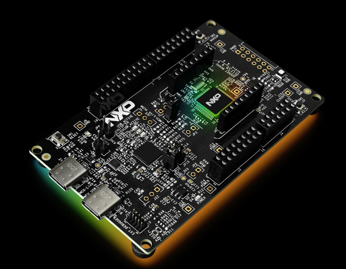
Introduction
This hands-on walks you through bringing a display to life on the FRDM-IMX95-PRO board. You will flash a BSP image to an SD card, attach a Waveshare 7" DSI LCD, select the correct device tree in U-Boot, and then exercise the panel with brightness control, screen rotation, capacitive touch, and a live camera video pipeline. By the end you will have a fully working touch display and the core skills to configure DSI panels on i.MX 95.
By the end of this hands-on you will be able to:
Flash a BSP image to a microSD card using UUU in Serial Download mode.
Connect the Waveshare 7" DSI display (FPC, power, and I2C) correctly.
Select the matching device tree for the panel from the U-Boot prompt.
Adjust and script the display backlight brightness.
Rotate the screen through Weston's configuration.
Verify capacitive touch with evtest .
Stream live camera video to the panel with GStreamer.
Hardware & Prerequisites
FRDM-IMX95-PRO board.
MicroSD card — 16 GB or larger.
Waveshare 7" DSI LCD — 1024×600 IPS, 5-point capacitive touch.
22-pin FPC cable.
Host PC with UUU installed.
Watch the Module Video
Watch the full hands-on walkthrough first to see each step performed on real hardware, then follow along on your own board using the steps below.
Steps to Run the Hands-On
1. Enter Serial Download Mode
Put the board into Serial Download Protocol (SDP) mode so the host can push the image, then connect it to your PC:
Set boot switch SW1 = 1000 (Serial Download Protocol mode).
Connect J7 USB-C to the host PC.
Connect J22 USB-C to view debug output on the serial console.
2. Flash the BSP Image with UUU
Run the following command on your host computer to flash the BSP boot image and full image to the SD card:
# --- UUU ---
# Run the following command on your host computer
uuu.exe –b sd_all imx-boot-imx95-19x19-lpddr5-frdm-pro-sd.bin-flash_a55 imx-image-full-imx95evk.wic.zst
3. Switch to SD Boot
Once flashing completes, reconfigure the board to boot from the SD card:
Power off the board.
Set boot switches SW3 and SW4 = 0011 (SD card boot).
Turn on the board.
4. Connect the Display — FPC Cable
Attach the 22-pin FPC cable between the board and the Waveshare panel, paying close attention to cable orientation on each end:
Connect the 22-pin FPC to the board's MIPI-DSI connector — the stiffener side faces the board connector.
Connect the other end to the Waveshare panel (15-pin side) — the conductive side faces the panel.
5. Connect the Display — Power & I2C
The panel needs both power and an I2C connection for the display output to come up:
Connect I2C via the J6 4-pin header.
Connect 5V power to J17 (or any 5V connector).
I2C must be connected for display output to work.
6. Change the Device Tree in U-Boot
Watch the serial console during boot and press any key at the U-Boot countdown to reach the prompt:
Hit any key to stop autoboot: 3
=> (U-Boot prompt)
At the U-Boot prompt, select the device tree for the Waveshare panel and boot:
# --- U-Boot: select the device tree for the display ---
fatls mmc 1
setenv fdtfile imx95-19x19-frdm-pro-waveshare-7inch-c-panel.dtb
saveenv
boot
7. Set & Check Backlight Brightness
Once Linux is running on the board, the panel backlight is exposed through sysfs. The commands below set a brightness value and read the current and maximum allowed values. Valid range is 0 (off) up to max_brightness . Run these as root:
# --- Linux on board ---
# Run the following command on the board
# Path to the backlight
/sys/class/backlight/3-0045/
# Set brightness
echo 128 > /sys/class/backlight/3-0045/brightness
# Read the current value
cat /sys/class/backlight/3-0045/brightness
# Read the maximum allowed value
cat /sys/class/backlight/3-0045/max_brightness
8. Fun Example — Breathing Backlight
For a quick visual test, this small script ramps the backlight up and down continuously, giving a "breathing" effect. Save it as breathe.sh , make it executable, and run it as root. Press Ctrl+C to stop.
# --- Linux ---
# Breathing back light
# Create and open the file
vi breathe.sh
# Write the following lines into the bash script
BL=/sys/class/backlight/3-0045
MAX=$(cat "$BL/max_brightness")
while true; do
for ((i=0; i<=MAX; i++)); do echo "$i" > "$BL/brightness"; sleep 0.01; done
for ((i=MAX; i>=0; i--)); do echo "$i" > "$BL/brightness"; sleep 0.01; done
done
# Change the permissions of the bash script
chmod +x breathe.sh
# Run the bash script
./breathe.sh
9. Rotate the Screen (Weston)
Display orientation is controlled in Weston's configuration file. Edit weston.ini , add an [output] section with the desired transform, then restart the service:
# --- Linux ---
# On board
# File path
/etc/xdg/weston/weston.ini
# Open the file
vi /etc/xdg/weston/weston.ini
# Add the following
[output]
name=DPI-1
transform=rotate-90
# Valid formats
# normal - 0 degrees (default)
# rotate-90 - 90 degrees clockwise
# rotate-180 - upside down
# rotate-270 - 270 degrees clockwise
# Reboot or restart the service
systemctl restart Weston
# Check the status of the service
systemctl status weston
You can confirm the panel resolution and active modes with modetest :
# --- Linux ---
# Check the panel resolution
modetest -c # list connectors & modes
# full DRM/KMS overview
modetest
# Look for the DSI/DPI connector and confirm
# 1024x600 is listed as an active mode
10. Test Capacitive Touch (evtest)
Run evtest with no arguments to list the available input devices, then select the touch screen's event number to start capturing touch events:
# --- Linux ---
# Touch screen evtest
# Run the evtest command
evtest
# It will list the available devices
Available devices:
/dev/input/event0: scmi_dev.11
/dev/input/event1: Goodix Capacitive TouchScreen
Select the device event number [0-1]: 1
# Then it will run the evtest of the touch screen
11. Display Camera Video (GStreamer)
Stream live camera video to the panel to verify both the camera and the display path in one go:
# --- Linux ---
# Gstreamer pipe line for webcam
# Run the following command
gst-launch-1.0 v4l2src device=/dev/video52 ! video/x-raw,width=640,height=480 ! Glimagesink
# Pipeline breakdown
# v4l2src device=/dev/video52 - capture from V4L2 node
# video/x-raw,width=640,height=480 - raw 640x480 video
# glimagesink - render on display via OpenGL
Troubleshooting
Symptom
What to check
No display output
Check FPC orientation — the stiffener side must face the board connector. Ensure the I2C bus (J6) is connected; it is required for display output.
fatls mmc 1 fails
Verify the SD card is inserted. Confirm SW3 and SW4 = 0011 (SD boot mode).
"No such file or directory" at the backlight path
Confirm the node name with ls /sys/class/backlight/ .
Touch not working after screen rotation
Add a calibration_matrix for the touch device in weston.ini , or configure the touch coordinate transform via libinput.
Conclusion
In this hands-on you brought up a Waveshare 7" DSI display on the FRDM-IMX95-PRO board from a fresh SD card flash all the way to a working touch panel with live camera video. Key takeaways:
Flashed a BSP image to the SD card with UUU and switched the board to SD boot.
Connected the DSI panel correctly (FPC orientation, 5V power, and the required I2C link).
Selected the matching device tree in U-Boot so the panel enumerates at 1024×600.
Controlled backlight brightness, rotated the display in Weston, validated touch with evtest , and verified the camera path with GStreamer.
Be sure to watch the module video above to see each step in action, and explore the rest of the FRDM-IMX95-PRO Training Hub for more hands-on modules.
記事全体を表示