- Forums
- Product Forums
- General Purpose MicrocontrollersGeneral Purpose Microcontrollers
- i.MX Forumsi.MX Forums
- QorIQ Processing PlatformsQorIQ Processing Platforms
- Identification and SecurityIdentification and Security
- Power ManagementPower Management
- Wireless ConnectivityWireless Connectivity
- RFID / NFCRFID / NFC
- Advanced AnalogAdvanced Analog
- MCX Microcontrollers
- S32G
- S32K
- S32V
- MPC5xxx
- Other NXP Products
- S12 / MagniV Microcontrollers
- Powertrain and Electrification Analog Drivers
- Sensors
- Vybrid Processors
- Digital Signal Controllers
- 8-bit Microcontrollers
- ColdFire/68K Microcontrollers and Processors
- PowerQUICC Processors
- OSBDM and TBDML
- S32M
- S32Z/E
-
- Solution Forums
- Software Forums
- MCUXpresso Software and ToolsMCUXpresso Software and Tools
- CodeWarriorCodeWarrior
- MQX Software SolutionsMQX Software Solutions
- Model-Based Design Toolbox (MBDT)Model-Based Design Toolbox (MBDT)
- FreeMASTER
- eIQ Machine Learning Software
- Embedded Software and Tools Clinic
- S32 SDK
- S32 Design Studio
- GUI Guider
- Zephyr Project
- Voice Technology
- Application Software Packs
- Secure Provisioning SDK (SPSDK)
- Processor Expert Software
- Generative AI & LLMs
-
- Topics
- Mobile Robotics - Drones and RoversMobile Robotics - Drones and Rovers
- NXP Training ContentNXP Training Content
- University ProgramsUniversity Programs
- Rapid IoT
- NXP Designs
- SafeAssure-Community
- OSS Security & Maintenance
- Using Our Community
-
- Cloud Lab Forums
-
- Knowledge Bases
- ARM Microcontrollers
- i.MX Processors
- Identification and Security
- Model-Based Design Toolbox (MBDT)
- QorIQ Processing Platforms
- S32 Automotive Processing Platform
- Wireless Connectivity
- CodeWarrior
- MCUXpresso Suite of Software and Tools
- MQX Software Solutions
- RFID / NFC
- Advanced Analog
-
- NXP Tech Blogs
- Home
- :
- Software Forums
- :
- S32 Design Studio
- :
- Another Bus Fault, Debug Hangs on WDOG_EWM_IRQHandler() Post
Another Bus Fault, Debug Hangs on WDOG_EWM_IRQHandler() Post
- Subscribe to RSS Feed
- Mark Topic as New
- Mark Topic as Read
- Float this Topic for Current User
- Bookmark
- Subscribe
- Mute
- Printer Friendly Page
Another Bus Fault, Debug Hangs on WDOG_EWM_IRQHandler() Post
- Mark as New
- Bookmark
- Subscribe
- Mute
- Subscribe to RSS Feed
- Permalink
- Report Inappropriate Content
I've read other posts that dealt with this issue so I understand it's not a watchdog issue.
https://community.nxp.com/t5/Kinetis-Microcontrollers/Debug-hangs-on-WDOG-EWM-IRQHandler/m-p/704955
https://community.nxp.com/t5/S32K/bus-fault-in-debugging-S32K144W/td-p/1208340
Things that could cause the issue:
Unhandled interrupt calling DefaultISR.
PTA4 grounded (JTAG TMS/ SWD-DIO) - I have ruled this out by measuring 2.6Mohm to ground and measuring 4.97V when powered on.
A little background on my issue:
Due to chip shortage I have switched from S32K146 to S32K144 (same part number otherwise). Originally I was using the 144 and switched to 146 for the same reason, now switching back. I've been developing on this custom board for months without issue. Programming with Multilink Universal ACP. I'm using Processor Expert for setup and yes I'm switching pin_mux configuration and generating code when I switch between processors.
Program works on S32K144EVB (both by programming it and during debug) but not on custom board with 64pin version of the 144. This goes for my current code base as well as trying with an example and also starting from scratch.
It should be noted that the program doesn't work at all, not just in debug mode as some others have found.
In every instance, the issue happens when initializing the pins using PINS_DRV_Init(). More specifically, when pins_driver.c calls PINS_Init(&config[i]). It jumps to pins_port_hw_access.c then to DefaultISR.
All I'm trying to do is flash an LED at this point. Everything is left default except for setting up 2 GPIO pins as outputs (PTE8 and PTD15).
If I comment out the pin init, the program moves through normally, though nothing happens because the pins aren't setup. If I manually set the pins up, it faults when I call PINS_DRV_SetPins(). If I manually set the pins, it faults there instead.
Every permutation of this works fine on the EVB but fails on custom board. I can even run it with another custom board with the 146 without even changing processor. This feels like a hardware issue so I'm going to put another processor on another board and see if that fixes the issue.
These chips came from a shady source and we paid a ransom to get them ($140/chip). Is it possible it's counterfeit? Would it even program if that were the case?
This round of PCBs has not been verified either, though it was a repeat order of a verified PCB. Hopefully they aren't the problem.
Thank you
- Mark as New
- Bookmark
- Subscribe
- Mute
- Subscribe to RSS Feed
- Permalink
- Report Inappropriate Content
Hi @sparkee,
Can you first identify the fault following this example:
https://community.nxp.com/t5/S32K-Knowledge-Base/Fault-handling-on-S32K14x/ta-p/1114447
Is it really a bus fault?
It seems like there is no problem to write the PCR_MUX and switch it to an output.
What is connected to the pin?
Can you scope the pin?
Can the switch short VDD power supply?
Does the MCU reset?
Can you scope PTA5 (reset_b) along with PTD15?
Thanks,
BR, Daniel
- Mark as New
- Bookmark
- Subscribe
- Mute
- Subscribe to RSS Feed
- Permalink
- Report Inappropriate Content
So I seemed to have solved the problem (sort of). I noticed that the PCC registers were showing clock disabled for PORTD and PORTE after the clock init sequence so I manually enabled them and now both boards are working fine.
I have trouble thinking this is the solution since:
a) It was working some of the time on 1 board, all of the time on the EVB and the 146 board
b) I've never needed to manually enable them in the past
c) They are enable in Processor Expert
Even if I'm doing something wrong in processor expert (this project I leave it as default), it doesn't explain why the examples didn't work either.
I definitely have it enabled in the clockMan
- Mark as New
- Bookmark
- Subscribe
- Mute
- Subscribe to RSS Feed
- Permalink
- Report Inappropriate Content
Hi @sparkee,
The bus interface clock is the usual suspect when a precise bus fault rises on an access to the peripheral registers.
But I ruled that out because, in the screenshot, I could see that the PORT registers could be read and had been written. Maybe you took the screenshot when it was working.
Maybe you enabled it but forgot to generate the code,
Regards,
Daniel
- Mark as New
- Bookmark
- Subscribe
- Mute
- Subscribe to RSS Feed
- Permalink
- Report Inappropriate Content
I hear you, but I was able to have it working and not working with zero code changes.
I've now tried the same thing with the helloworld example and it does not work. Gets hung on PINS_DRV_Init() just like before.
- Mark as New
- Bookmark
- Subscribe
- Mute
- Subscribe to RSS Feed
- Permalink
- Report Inappropriate Content
Hi Dylan,
Can you read the generated configuration, then step the code to see if the clock gets enabled.
I wonder, once you set the bit in the PCC register and read the register back, whether it it is set or not.
And if so, does it still generate this bus fault?
Anyway, you mentioned that the source of the MCU was shady.
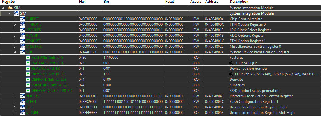
Can you read the SIM_SDID System Device Identification Register?
Thanks,
Daniel
- Mark as New
- Bookmark
- Subscribe
- Mute
- Subscribe to RSS Feed
- Permalink
- Report Inappropriate Content
CLOCK_SYS_UpdateConfiguration(0U, CLOCK_MANAGER_POLICY_AGREEMENT);
This function returns STATUS_TIMEOUT
It appears the clock manager is not setting up correctly.
I believe line 571 does not result in STATUS_SUCCESS so it never sets up PCC settings.
    /* Set SCG settings. */
    result = CLOCK_SYS_SetScgConfiguration(&cfg->scgConfig);
I have 2 identical PCBs except one has the S32K144 and the second has the S32K146. With the processor set to 144_64, I can get the hello_world program to work correctly on the 146 but not the 144. I step through with the 146 and the code above results in STATUS_SUCCESS.\
- Mark as New
- Bookmark
- Subscribe
- Mute
- Subscribe to RSS Feed
- Permalink
- Report Inappropriate Content
Hi @sparkee,
I'm not able to reproduce it on my S32K144 board.
Are you sure this is the issue, if you over-write the result
result = STATUS_SUCCESS;before
CLOCK_SYS_SetPccConfiguration(&cfg->pccConfig);does it work?
At which point the CLOCK_SYS_SetScgConfiguration() function changes the status from STATUS_SUCCESS?
Regards,
Daniel
- Mark as New
- Bookmark
- Subscribe
- Mute
- Subscribe to RSS Feed
- Permalink
- Report Inappropriate Content
I have it as a watch and it is STATUS_SUCCESS until it hits that line, then it switches.
My coworker noticed that when changing from 146 processor to 144 processor then generating PE files, the SDK file S32K144_features.h file generates empty. When generating the 146, the features file generates correctly with clock enable information and the program runs correctly.
- Mark as New
- Bookmark
- Subscribe
- Mute
- Subscribe to RSS Feed
- Permalink
- Report Inappropriate Content
Hi,
I don't know why the file does not get generated.
Can you create separate projects for both MCUs or do you need to have just one project?
Thanks,
Daniel
- Mark as New
- Bookmark
- Subscribe
- Mute
- Subscribe to RSS Feed
- Permalink
- Report Inappropriate Content
My apologies for running you through all this. Turns out the PCB assembly company placed the wrong oscillator on the boards and that has been causing the processor to be flaky. I had to pull out the microscope to figure it out. There were too many variables with the latest batch of boards and since they were operating correctly some of the time I didn't investigate it thoroughly enough. I appreciate the support and hope I didn't waste too much of your time @danielmartynek
Now the 144 will even run the code from the 146 after juggling the timers.
- Mark as New
- Bookmark
- Subscribe
- Mute
- Subscribe to RSS Feed
- Permalink
- Report Inappropriate Content
Thank you for the update.
I'm glad you resolved it.
Regards,
Daniel
- Mark as New
- Bookmark
- Subscribe
- Mute
- Subscribe to RSS Feed
- Permalink
- Report Inappropriate Content
I had to jump on another project but I'm back.
After getting the LEDs to blink on a project from scrap, I've jumped back to the hello_world example project.
I'm getting STATUS_TIMEOUT returned from clock_s32K1xx.c
The PCC_FTFC register has the clock enabled, but no other peripherals. I'm only trying to enable Port D and E.
I then enable the port clocks manually, which fixed the other project, and I see the registers change correctly. Then I'm back to the same BusFault when initializing the pins.
SDID looks ok as far as I can tell, though I have very little knowledge of this.
- Mark as New
- Bookmark
- Subscribe
- Mute
- Subscribe to RSS Feed
- Permalink
- Report Inappropriate Content
Hi,
The SDID register looks correct for an S32K144 MCU.
Which version of the S32DS IDE and the SDK do you have?
Can you attach a test project so that I can debug it on my side?
You can create a ticket if you don't want to share it here?
Thanks,
BR, Daniel
- Mark as New
- Bookmark
- Subscribe
- Mute
- Subscribe to RSS Feed
- Permalink
- Report Inappropriate Content
- Mark as New
- Bookmark
- Subscribe
- Mute
- Subscribe to RSS Feed
- Permalink
- Report Inappropriate Content
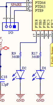
As for what is connected? PTD15 is connected to a female header as a spare pin and PTE8 is connected to an LED.
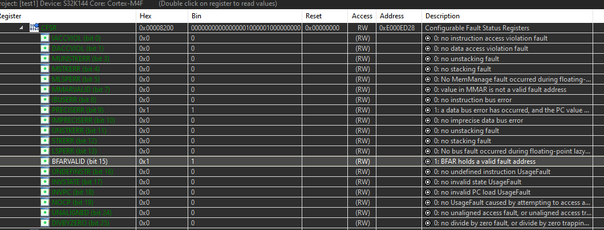
Thank you for your reply @danielmartynek. A strange thing has happened. I built a second board and got the same error. I scoped PTA5 and I see 5V except for a quick reset when loading the program. The first time I did it, it through the fault like normal and I saw nothing on PTA5. The second time, I moved scope to PTD15 and the board is actually running fine and no fault. I added code for PTE8 to be an output and the LED is also blinking. I was even able to switch back to the SDK code instead of setting registers manually. I was able to remove the probe from the board and continue running fine. I switch the first board back in, no change to code, I get the fault again. See below for register values.
I was pulled into something else but now back to the first board which was working intermittently and now I can't get it to work. No code changes. Tried probing but no change. PTA5 not resetting, holding 5V after initial programming.
I'm not entirely sure I know what you wanted me to do after reading your post you linked me to, other than looking at the registers above. Was there something more specific I should have done?


