
- Forums
- Product Forums
- General Purpose MicrocontrollersGeneral Purpose Microcontrollers
- i.MX Forumsi.MX Forums
- QorIQ Processing PlatformsQorIQ Processing Platforms
- Identification and SecurityIdentification and Security
- Power ManagementPower Management
- Wireless ConnectivityWireless Connectivity
- RFID / NFCRFID / NFC
- Advanced AnalogAdvanced Analog
- Neural Processing UnitsNeural Processing Units
- MCX Microcontrollers
- S32G
- S32K
- S32V
- MPC5xxx
- Other NXP Products
- S12 / MagniV Microcontrollers
- Powertrain and Electrification Analog Drivers
- Sensors
- Vybrid Processors
- Digital Signal Controllers
- 8-bit Microcontrollers
- ColdFire/68K Microcontrollers and Processors
- PowerQUICC Processors
- OSBDM and TBDML
- S32M
- S32Z/E
-
- Solution Forums
- Software Forums
- MCUXpresso Software and ToolsMCUXpresso Software and Tools
- CodeWarriorCodeWarrior
- MQX Software SolutionsMQX Software Solutions
- Model-Based Design Toolbox (MBDT)Model-Based Design Toolbox (MBDT)
- FreeMASTER
- eIQ Machine Learning Software
- Embedded Software and Tools Clinic
- S32 SDK
- S32 Design Studio
- GUI Guider
- Zephyr Project
- Voice Technology
- Application Software Packs
- Secure Provisioning SDK (SPSDK)
- Processor Expert Software
- Generative AI & LLMs
-
- Topics
- Mobile Robotics - Drones and RoversMobile Robotics - Drones and Rovers
- NXP Training ContentNXP Training Content
- University ProgramsUniversity Programs
- Rapid IoT
- NXP Designs
- SafeAssure-Community
- OSS Security & Maintenance
- Using Our Community
-
- Cloud Lab Forums
-
- Knowledge Bases
- ARM Microcontrollers
- i.MX Processors
- Identification and Security
- Model-Based Design Toolbox (MBDT)
- QorIQ Processing Platforms
- S32 Automotive Processing Platform
- Wireless Connectivity
- CodeWarrior
- MCUXpresso Suite of Software and Tools
- MQX Software Solutions
- RFID / NFC
- Advanced Analog
- Neural Processing Units
-
- NXP Tech Blogs
- Home
- :
- モデルベース・デザイン・ツールボックス(MBDT)
- :
- モデルベース・デザイン・ツールボックス(MBDT)
- :
- Re: S32K344- Interrupt based PWM generation
S32K344- Interrupt based PWM generation
- RSS フィードを購読する
- トピックを新着としてマーク
- トピックを既読としてマーク
- このトピックを現在のユーザーにフロートします
- ブックマーク
- 購読
- ミュート
- 印刷用ページ

- 新着としてマーク
- ブックマーク
- 購読
- ミュート
- RSS フィードを購読する
- ハイライト
- 印刷
- 不適切なコンテンツを報告
Requirement is like, want to generate two PWM signals and one PWM signal should start to generate other signal rising edge and stop at falling edge. To achieve this, Is any library or supported document available?
解決済! 解決策の投稿を見る。

 dragostoma
- 新着としてマーク
- ブックマーク
- 購読
- ミュート
- RSS フィードを購読する
- ハイライト
- 印刷
- 不適切なコンテンツを報告
Hi, @Er_AK ,
First of all, I apologize for the delayed response. You could find attached a possible solution for your application, which I will describe below:
1. PWM channel 0 configuration
- configured based on instance eMIOS 0 channel 9;
- has a default period set to 64000 ticks;
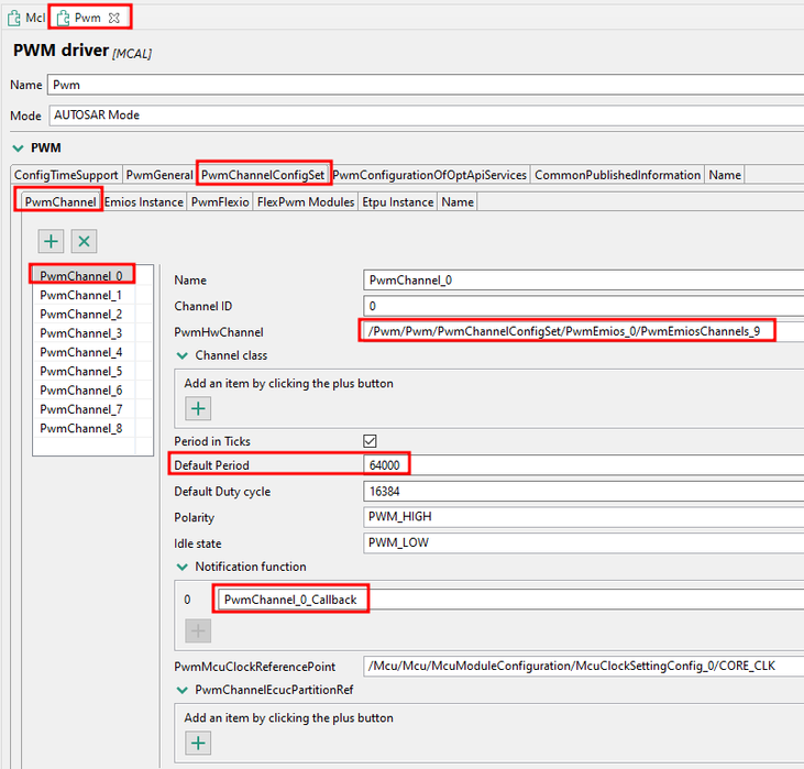
- based on the eMIOS instance, has assigned PwmEmiosChannels_9 configuration;
- flag generation is set to Both_Trailing_and_Leading_Edge, meaning that the Interrupt Callback Notification will be triggered at each edge (rising and falling edge);

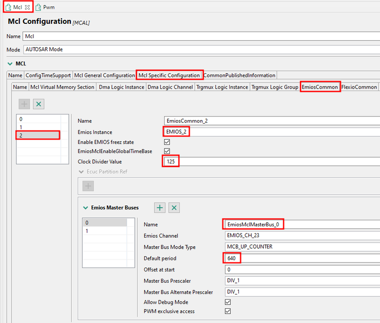
- configured based on EmiosCommon_0, which uses a clock divider value of 125;
- uses EmiosMclMasterBus_0 (EMIOS_CH_23), with a default period of 64000;

2. PWM channel 8 configuration
- configured based on instance eMIOS 2 channel 7;
- has a default period set to 640 ticks;
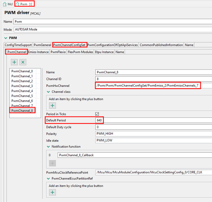
- based on the eMIOS instance, has assigned PwmEmiosChannels_7 configuration;
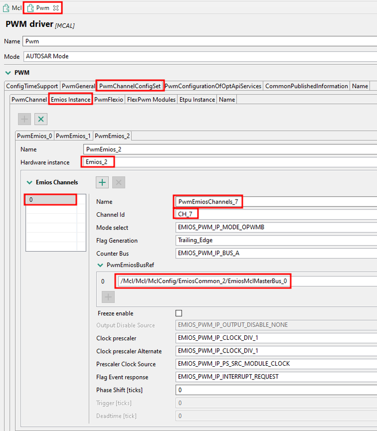
- configured based on EmiosCommon_2, which uses a clock divider value of 125;
- uses EmiosMclMasterBus_0 (EMIOS_CH_23), with a default period of 640;
3. Simulink application

The Simulink application consists of:
3.1. Initialize subsystem where the notifications are enabled for the PWM channels:

3.2. Main application:
- the PWM Channel 0 generates the signal based on the above configuration;
- the edgeFlag variable is initially set to 0, and its purpose is to detect the edge of the generated PWM;
3.3. Hardware Interrupt Callback:

- the RGBLED0_BLUE is toggling at each interrupt callback trigger, and its purpose is to follow the PWM signal;
- when the edgeFlag is set to 1, a Rising Edge is detected on the PWM Channel 0, and the PWM Channel 8 starts to generate the signal based on the above configuration; the edgeFlag is set to 0;
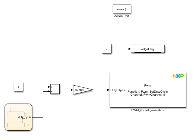
- when the edgeFlag is 0, a FallingEdge was detected on the PWM Channel 0 and the PWM Channel 8 stops the generation of the signal; the edgeFlag is set to 1;

4. Connections
To be able to validate the results, you should connect the Logic Analyzer to the following pins:
- PTA1: PWM0 set to emios_0_ch_9_ch
- PTD26: PWM8 set to emios_2_ch_7_ch
- PTA31: RGBLED0_BLUE

5. Results
Based on the above configuration, the PWM signals will be defined as follows:



6. Conclusion
The PWM Channel 0 will generate a PWM signal with a 20 Hz frequency. At each PWM Channel 0 edge change, the RGBLED0_BLUE is toggling, and based on a flag initially set to 0, the PWM edge that triggered the interrupt callback is determined. When a rising edge is detected, PWM Channel 8 starts to generate a PWM signal with a 2 kHz frequency. When a falling edge is detected, PWM Channel 8 stops to generate the PWM signal.
I hope this application helps you achieve your goal.
Best regards,
Dragos
dragostoma
- 新着としてマーク
- ブックマーク
- 購読
- ミュート
- RSS フィードを購読する
- ハイライト
- 印刷
- 不適切なコンテンツを報告
Hi, @Er_AK,
We appreciate your interest in the S32K3 Model-Based Design Toolbox.
I understand that you are trying to generate 2 PWM signals, where the first PWM signal starts at the rising edge and stops at the falling edge of the second PWM signal.
The latest version of toolbox (1.5.0) introduced support for the ICU (Input Capture Unit) component, and also a model example that you can use as a reference in your application - s32k3xx_icu_signal_edge_detect_ebt. This model uses the Signal Edge Detect operating mode and uses the SIUL2 module to detect edges of an input signal.
Now, to achieve your goal in your application, you should use eMIOS (Enhanced Modular Input Output Subsystem) module which is highly suitable for generating PWM signals due to its flexibility and functionality designed specifically for such tasks. You can configure eMIOS to generate both of your required PWM signals with precise control over their parameters like frequency and duty cycle.
Moreover, SIUL2 (System Integration Unit Lite 2) can be used effectively for detecting edges (rising and falling) on the second PWM signal. Since SIUL2 is capable of configuring external interrupt lines based on specific edge detection, it can be set up to monitor the second PWM signal and generate interrupts when a rising or falling edge occurs.
I hope this will help you and be a starting point in reaching the goal of your application.
Regards,
Dragos
- 新着としてマーク
- ブックマーク
- 購読
- ミュート
- RSS フィードを購読する
- ハイライト
- 印刷
- 不適切なコンテンツを報告
Hi, @dragostoma ,
Thanks for the reply. Went through the example. My understanding from the example is that we have to feed one PWM as input and the second one generate based on the input PWM.
But here, both PWM has to genrate,v ie, no input signal.
For example, 10KHz PWM signal will generate and feed this to external circuit. The second PWM is 1KHz and the PWM will generate when 10KHz PWM rising edge and will stop on falling edge.
Is the given method will work for the same?
How the edges will detect internally?
dragostoma
- 新着としてマーク
- ブックマーク
- 購読
- ミュート
- RSS フィードを購読する
- ハイライト
- 印刷
- 不適切なコンテンツを報告
Hi, @Er_AK ,
First of all, I apologize for the delayed response. You could find attached a possible solution for your application, which I will describe below:
1. PWM channel 0 configuration
- configured based on instance eMIOS 0 channel 9;
- has a default period set to 64000 ticks;
- based on the eMIOS instance, has assigned PwmEmiosChannels_9 configuration;
- flag generation is set to Both_Trailing_and_Leading_Edge, meaning that the Interrupt Callback Notification will be triggered at each edge (rising and falling edge);
- configured based on EmiosCommon_0, which uses a clock divider value of 125;
- uses EmiosMclMasterBus_0 (EMIOS_CH_23), with a default period of 64000;
2. PWM channel 8 configuration
- configured based on instance eMIOS 2 channel 7;
- has a default period set to 640 ticks;
- based on the eMIOS instance, has assigned PwmEmiosChannels_7 configuration;
- configured based on EmiosCommon_2, which uses a clock divider value of 125;
- uses EmiosMclMasterBus_0 (EMIOS_CH_23), with a default period of 640;
3. Simulink application
The Simulink application consists of:
3.1. Initialize subsystem where the notifications are enabled for the PWM channels:
3.2. Main application:
- the PWM Channel 0 generates the signal based on the above configuration;
- the edgeFlag variable is initially set to 0, and its purpose is to detect the edge of the generated PWM;
3.3. Hardware Interrupt Callback:
- the RGBLED0_BLUE is toggling at each interrupt callback trigger, and its purpose is to follow the PWM signal;
- when the edgeFlag is set to 1, a Rising Edge is detected on the PWM Channel 0, and the PWM Channel 8 starts to generate the signal based on the above configuration; the edgeFlag is set to 0;
- when the edgeFlag is 0, a FallingEdge was detected on the PWM Channel 0 and the PWM Channel 8 stops the generation of the signal; the edgeFlag is set to 1;
4. Connections
To be able to validate the results, you should connect the Logic Analyzer to the following pins:
- PTA1: PWM0 set to emios_0_ch_9_ch
- PTD26: PWM8 set to emios_2_ch_7_ch
- PTA31: RGBLED0_BLUE
5. Results
Based on the above configuration, the PWM signals will be defined as follows:
6. Conclusion
The PWM Channel 0 will generate a PWM signal with a 20 Hz frequency. At each PWM Channel 0 edge change, the RGBLED0_BLUE is toggling, and based on a flag initially set to 0, the PWM edge that triggered the interrupt callback is determined. When a rising edge is detected, PWM Channel 8 starts to generate a PWM signal with a 2 kHz frequency. When a falling edge is detected, PWM Channel 8 stops to generate the PWM signal.
I hope this application helps you achieve your goal.
Best regards,
Dragos
