Objectives
In this lab, you will learn:
How to use the MCUXpresso Installer to obtain NXP Software (FreeMASTER)
How to use Application Code Hub to import an example into the VS Code workspace
How to build, clean, debug, and run the example.
How to connect the Serial Monitor for UART console
How FreeMASTER can be used as a real-time debug monitor and data visualization tool
Hardware Requirements
Personal Computer
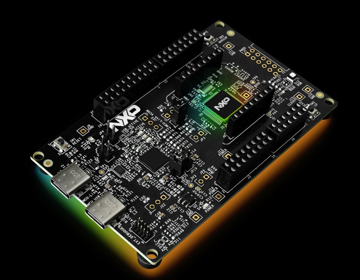
FRDM-MCXA153 Board
Heart Rate 4 CLICK Module (MIKROE 5547)
USB type-C cable
Software Requirements
MCUXpresso for VS Code
FreeMASTER v3.2 or latest
FRDM-MCXA153 SDK
Application Code Hub The Application Code Hub (ACH) repository enables engineers to easily find microcontroller software examples, code snippets, application software packs and demos developed by NXP in-house experts. This space provides a quick, easy and consistent way to find microcontroller applications. Find more information at www.nxp.com/ach.
Installing Prerequisites
- Launch MCUXpresso for VS Code
- Launch the MCUXpresso Installer from the QUICKSTART PANEL
- Install MCUXpresso SDK Developer, LinkServer, and FreeMASTER
Heart Rate Monitor Lab The NXP Application Code Hub provides a complete example of how to use the MCXA-153 microcontroller in a Heart Rate and SPO2 monitor application. This lab will walk through the steps to import, build, program and debug the example. The final section of the lab shows how to use FreeMASTER as a data-visualization tool for the acquired sensor data on the FRDM-MCXA153 development board.
1. Go to the Quick Start Panel
2. Select Application Code Hub
3. Filter Visible Examples (MCX + Sensors) - Go to the filter section next to the Search bar and select two filters. - Select MCX in the Device Families Section and Sensor in the Categories section of the filters
4. Search for Keywords in Examples - Search for the keyword 'heart rate'. - Select the demo "frdm mcxa153 freemaster heart rate".
5. Read Overview of Heart Rate Demo The Application Code Hub provides a consistent Readme Overview for every project. The FreeMASTER Heart Rate demo overview is previewed after clicking on the application card. Scroll through the readme to become familiar with the available contents like required hardware, software and setup instructions.
6. Select Destination for Project The wizard automatically provides a prompt to browse to a desired destination folder. Create the destination C:\NXP_ACH to store the project here. Or you can specify a custom location.
7. Import Project into Workspace Select Import Project(s) after entering the desired location. If a valid project is not available, the wizard only displays Import Repository, to allow a code repo, without a project, to be added to workspace.
8. Select Detected Project(s) The import wizard will scan the example repo and list valid projects that were discovered. This allows the user to select only the projects they want created. Select the mcuxpresso project listed at the top of the VS Code window.
9. Associate a Toolchain The last selection is to identify the Compiler toolchain to be used for the project. GCC will be used for this project. Select Arm GNU Toolchain 12.3.Rel1 (Or latest version available from MCUXpresso Installer prework) The scan may locate Compilers associated with MCUXPresso IDE. Verify the path and version between listed compilers.
At this time the wizard will complete the project import. A Successful Conversion notification is displayed at the bottom of the screen. It is important to recognize that the selected Heart Rate example is a working project within the MCUXpresso IDE (Eclipse based). The VS Code extension has the ability to convert an existing MCUXpresso IDE projects for development in VS Code. 10. Navigating a Project in VS Code The MCUXpresso for VS Code extension includes a PROJECTS section to help users access useful project information. Users can review and modify project information with the following steps. Review Project Details Project details are shown in the Dropdown menu of the Projects Section in the MCUXpresso Extension Navigation Pane. • Settings: Workspace settings specific to the project
• MCU: Targeted device.
• Build Configurations: Select build configuration from available list (i.e. Debug or Release).
• Debug Configurations:
• Repository Information
• Project Files
11. Working with Source Files There are two ways to view and modify the project's files: • Click on the Explorer Icon at the top of the VS Code left navigation pane.
• Expand the Project Files section from the PROJECTS view
12. Build the application The MCXA153 FreeMASTER Heart Rate project needs to build the application image. After the code builds without any errors, the application can be run on the FRDM board. The following steps require that you return to the MCUXpresso perspective by clicking the MCUXpresso for VS Code X icon in the Activity bar
Build the project by clicking the Build Selected icon. After a successful build, the Terminal console displays the memory usage (or compiler errors if any).
13. Connect Serial Monitor to the board To use the Serial Monitor integrated into VS Code:
- Connect the USB-C cable to J15 to power the FRDM board. The onboard debugger provides a USBUART bridge to interface with the Serial monitor.
- Click on the SERIAL MONITOR found as a tab in the Terminal window at the Bottom of VS Code Window. NOTE: The default COM settings are valid for NXP eval boards: "115200, None..."
- Click Start Monitoring to connect the monitor to the FRDM board’s auto-detected COM port.
VS Code in light theme
14. Flash/Debug the Application This section uses the on-board debugger to connect to the MCU, and program the flash. LinkServer from NXP manages the GDB server for communicating with the NXP MCULink on-board debug probe. It includes support for flash programming.
- Click the play icon to Debug the application: The application is flashed to the FRDM board and VS Code switches to the Debug perspective. Return to the SERIAL MONITOR tab under the Terminals. It switches to the OUTPUT terminal when a Debug session is started.
VS Code in light theme
- The execution will be paused on a breakpoint. Click Continue/Play icon to continue execution. The application will advance to the start of main().
- Click Continue/Play icon a 2nd time for the Heart Rate application to launch inside main().
15. View Heart Rate Values in Serial Terminal
The Heart Rate application using the serial port to display information. The following should be displayed in the SERIAL MONITOR tab after main() starts.
Place a finger on the sensor near the Heart silkscreened on Heart Rate 4 click board. The following should be displayed in the SERIAL MONITOR tab after a finger is placed on the sensor:
A heart rate value will be calculated and displayed after
16. FreeMASTER Data Visualization FreeMASTER is a standalone application provided by NXP to help developers visualize, monitor and manipulate data available from their projects. The Heart Rate example includes a /freemaster folder that helps users get started using the tool.
The settings in the Application Code Hub were established for an MCUXpresso IDE based project. There are a few changes that need to be made after the project is converted to a VS Code project.
The following steps will properly configure FreeMASTER to work with the Heart Rate example project:
Launch FreeMASTER Application There are two options for launching FreeMASTER.
• Click on the heart_rate.pmpx using File Explorer. The FreeMASTER application should be associated with .pmpx file extensions. This will also automatically load the included project settings.
• Launch FreeMASTER by searching Windows Applications.
• This will not load project settings. You will be required to Open Project using the FreeMaster menu as shown. Open the .pmpx project file.
• Verify Project Options FreeMASTER has a few key settings to verify once a project is opened. A user should verify they are correctly set for the type of Debug Probe and location of the project output files. - Click Project -> Options from the menu bar.
- Verify that the correct method is set for communicating with the board. The on-board Debug Probe for the FRDM-MCXA153 is by default shipped with NXP CMSIS-DAP firmware. Select FreeMASTER CMSIS-DAP Communication Plug-in found under the Comm tab, for Plug-in module:
- Verify that the correct Default symbol file is targeted for the VS Code project. The symbol file in VS Code projects is output under an /armgcc folder. Select the /armgcc folder within VS Code project MAP Files tab. The window will autodetect the Binary ELF File, and display this under File format:
- Visualize Data From Heart Rate Project The NXP software team has included a default visualization for the Heart Rate project. The demonstration showcases the different styles for project data to be shown. The following visualization settings are preset for the Heart Rate project:
Welcome HTML Page: The HTML Pages (Under Options) points to welcome.html file. This provides structured web view for displaying elements. Beyond scope of this lab, but .html file can be reviewed to see how target values/charts are referenced in html. Oscilloscope Visual: View plots the values of a project variable. The plot axis are configured for scale and color. Heart Rate, SPO2 and ECG are configured. Variable Watch Table: After variables are configured to be tracked, they can be added to this table view.
Make sure that the debug probe is not in an active debug session in the IDE or VS Code. Click GO icon on the menu bar to initiate the project data visualization! The following points are highlighted for the FreeMASTER output.
1. Clicking on the elements listed under the Project Tree changes the view to the specific Oscilloscope Visual.
2. View the captured values for the variables in a Table view.
3. Visualization of data organized based on the layout defined in the Welcome.html.
View full article