
- Forums
- Product Forums
- General Purpose MicrocontrollersGeneral Purpose Microcontrollers
- i.MX Forumsi.MX Forums
- QorIQ Processing PlatformsQorIQ Processing Platforms
- Identification and SecurityIdentification and Security
- Power ManagementPower Management
- Wireless ConnectivityWireless Connectivity
- RFID / NFCRFID / NFC
- Advanced AnalogAdvanced Analog
- Neural Processing UnitsNeural Processing Units
- MCX Microcontrollers
- S32G
- S32K
- S32V
- MPC5xxx
- Other NXP Products
- S12 / MagniV Microcontrollers
- Powertrain and Electrification Analog Drivers
- Sensors
- Vybrid Processors
- Digital Signal Controllers
- 8-bit Microcontrollers
- ColdFire/68K Microcontrollers and Processors
- PowerQUICC Processors
- OSBDM and TBDML
- S32M
- S32Z/E
-
- Solution Forums
- Software Forums
- MCUXpresso Software and ToolsMCUXpresso Software and Tools
- CodeWarriorCodeWarrior
- MQX Software SolutionsMQX Software Solutions
- Model-Based Design Toolbox (MBDT)Model-Based Design Toolbox (MBDT)
- FreeMASTER
- eIQ Machine Learning Software
- Embedded Software and Tools Clinic
- S32 SDK
- S32 Design Studio
- GUI Guider
- Zephyr Project
- Voice Technology
- Application Software Packs
- Secure Provisioning SDK (SPSDK)
- Processor Expert Software
- Generative AI & LLMs
-
- Topics
- Mobile Robotics - Drones and RoversMobile Robotics - Drones and Rovers
- NXP Training ContentNXP Training Content
- University ProgramsUniversity Programs
- Rapid IoT
- NXP Designs
- SafeAssure-Community
- OSS Security & Maintenance
- Using Our Community
-
- Cloud Lab Forums
-
- Knowledge Bases
- ARM Microcontrollers
- i.MX Processors
- Identification and Security
- Model-Based Design Toolbox (MBDT)
- QorIQ Processing Platforms
- S32 Automotive Processing Platform
- Wireless Connectivity
- CodeWarrior
- MCUXpresso Suite of Software and Tools
- MQX Software Solutions
- RFID / NFC
- Advanced Analog
- Neural Processing Units
-
- NXP Tech Blogs
- Home
- :
- i.MX Forums
- :
- i.MX Processors
- :
- Re: iMX6DQ uSDHC Stand Alone Driver
iMX6DQ uSDHC Stand Alone Driver
- Subscribe to RSS Feed
- Mark Topic as New
- Mark Topic as Read
- Float this Topic for Current User
- Bookmark
- Subscribe
- Mute
- Printer Friendly Page
iMX6DQ uSDHC Stand Alone Driver

- Mark as New
- Bookmark
- Subscribe
- Mute
- Subscribe to RSS Feed
- Permalink
- Report Inappropriate Content
I'm struggling to get a working stand alone (not using linux) uSDHC driver. I have a working driver (based on the SDK which works for everything except for reads and writes. When I read a block, I get back all zeros instead of actual data. The board and SD card are good - I can boot linux from that card and board.
Does anyone have a stand alone driver they're willing to share, or have any ideas on where to look for the problem? This is for the iMX6Q.
 joanxie
- Mark as New
- Bookmark
- Subscribe
- Mute
- Subscribe to RSS Feed
- Permalink
- Report Inappropriate Content
- Mark as New
- Bookmark
- Subscribe
- Mute
- Subscribe to RSS Feed
- Permalink
- Report Inappropriate Content
Thank you for your response. Using the iMX6 SDK, and the code you sent I got it to compile and run. There were no reported errors. This is what the code you sent read back from sector 0 (FAT 32 MBR) of a good SD card:
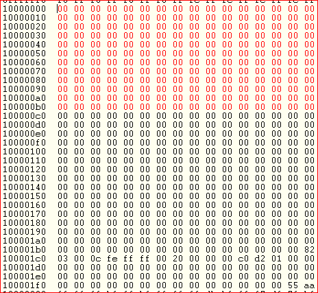
Here is what is actually on the (same) card, same sector:
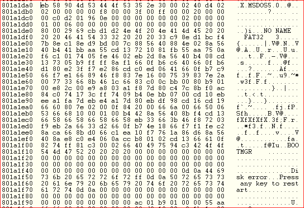
This was read using a Vybrid processor. How do I get from point A to point B? Again - the board is a Boundary Devices (known good, boots and run linux from an SD card (obviously not the card above).
This is my frustration - what is causing the controller to incorrectly read the card? Again, this is using the code you sent.
- Mark as New
- Bookmark
- Subscribe
- Mute
- Subscribe to RSS Feed
- Permalink
- Report Inappropriate Content
Because I've read the same values using several different drivers, and several different cards, I think the reading process is correct. I wonder if the wrong block is being read. As far as I know the block number is inserted in the CMD18 argument. Any thoughts on that?
- Mark as New
- Bookmark
- Subscribe
- Mute
- Subscribe to RSS Feed
- Permalink
- Report Inappropriate Content
Anyone out there have a working driver for the iMX6 Quad uSDHC controller? Anyone know which file u-boot uses? I thought it was drivers/mmc/sdhci.c, but that driver does not use the MIX register.
- Mark as New
- Bookmark
- Subscribe
- Mute
- Subscribe to RSS Feed
- Permalink
- Report Inappropriate Content
After searching for awhile I found the "main" u-boot usdhc file. Depending on whose download you use it's called by different names; but try fsl_usdhc.c or fsl_usdhc_imx.c. In comparing the SDK files that I had previously to the ones Jodi sent, I found a small difference - on the later ones I found the later one does a dcache flush and invalidate of the read buffer depending on the state of the dcache. In my standalone driver I don't turn on the caches or the mmu:
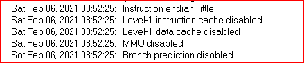
The above is from the debugger when it starts up. I do this to avoid having to set up the caches. My question is do the caches need to be functional before the sdhc will work properly?
I can find no differences between my driver and any of the SDKs, or the u-boot driver (except the u-boot driver does use caches/mmu). The only issue with my driver is that data is read incorrectly. That means to me that there is something going on that the manual doesn't mention or there is an errata regarding reads and writes I haven't found. I know that the sdhc cannot burst into/out of OCRAM - only system (DDR) memory. I also know that the buffer must start on a 32-bit boundary. Any comments??
- Mark as New
- Bookmark
- Subscribe
- Mute
- Subscribe to RSS Feed
- Permalink
- Report Inappropriate Content
I've checked my driver against the SDK, u-boot driver, and Linux driver, and there are no major differences. I've tried with the cache/mmu enabled and disabled - no difference. Therefore I'm convinced that the error is most likely not in the uSDHC driver. It appears like there is a data disconnect somewhere between the pins and memory - the data coming in on the pins is not getting to memory. Here is how the GPIO pins are programmed:
// CD3_CMD on SD3_CMD - ALT 0
IOMUXC_SW_MUX_CTL_PAD_SD3_CMD = PAD_ALT_FUNC_0;
IOMUXC_SW_PAD_CTL_PAD_SD3_CMD = PAD_CTL_PUS_100K_PU |
PAD_CTL_ODE_DISABLED |
PAD_CTL_SPEED_MAX |
PAD_CTL_DSE_38ohm |
PAD_CTL_HYS_ENABLED |
PAD_CTL_SRE_FAST;
// CD3_CLK on SD3_CLK - ALT 0
IOMUXC_SW_MUX_CTL_PAD_SD3_CLK = PAD_ALT_FUNC_0;
IOMUXC_SW_PAD_CTL_PAD_SD3_CLK = PAD_CTL_PUS_100K_PU |
PAD_CTL_ODE_DISABLED |
PAD_CTL_SPEED_MAX |
PAD_CTL_DSE_38ohm |
PAD_CTL_HYS_ENABLED |
PAD_CTL_SRE_FAST;
// CD3_DET on SD3_DAT5 - ALT 5 (GPIO7 bit 0)
IOMUXC_SW_MUX_CTL_PAD_SD3_DATA5 = PAD_ALT_FUNC_5;
IOMUXC_SW_PAD_CTL_PAD_SD3_DATA5 = PAD_CTL_PUS_22K_PU |
PAD_CTL_ODE_DISABLED |
PAD_CTL_SPEED_MED |
PAD_CTL_DSE_38ohm |
PAD_CTL_HYS_ENABLED |
PAD_CTL_SRE_SLOW;
// CD3_DAT3 on SD3_DATA3 - ALT 0
IOMUXC_SW_MUX_CTL_PAD_SD3_DATA3 = PAD_ALT_FUNC_0;
IOMUXC_SW_PAD_CTL_PAD_SD3_DATA3 = PAD_CTL_PUS_100K_PU |
PAD_CTL_ODE_DISABLED |
PAD_CTL_SPEED_MAX |
PAD_CTL_DSE_38ohm |
PAD_CTL_HYS_ENABLED |
PAD_CTL_SRE_FAST;
// CD3_DAT2 on SD3_DATA2 - ALT 0
IOMUXC_SW_MUX_CTL_PAD_SD3_DATA2 = PAD_ALT_FUNC_0;
IOMUXC_SW_PAD_CTL_PAD_SD3_DATA2 = PAD_CTL_PUS_100K_PU |
PAD_CTL_ODE_DISABLED |
PAD_CTL_SPEED_MAX |
PAD_CTL_DSE_38ohm |
PAD_CTL_HYS_ENABLED |
PAD_CTL_SRE_FAST;
// CD3_DAT1 on SD3_DATA1 - ALT 0
IOMUXC_SW_MUX_CTL_PAD_SD3_DATA1 = PAD_ALT_FUNC_0;
IOMUXC_SW_PAD_CTL_PAD_SD3_DATA1 = PAD_CTL_PUS_100K_PU |
PAD_CTL_ODE_DISABLED |
PAD_CTL_SPEED_MAX |
PAD_CTL_DSE_38ohm |
PAD_CTL_HYS_ENABLED |
PAD_CTL_SRE_FAST;
// CD3_DAT0 on SD3_DATA0 - ALT 0
IOMUXC_SW_MUX_CTL_PAD_SD3_DATA0 = PAD_ALT_FUNC_0;
IOMUXC_SW_PAD_CTL_PAD_SD3_DATA0 = PAD_CTL_PUS_100K_PU |
PAD_CTL_ODE_DISABLED |
PAD_CTL_SPEED_MAX |
PAD_CTL_DSE_38ohm |
PAD_CTL_HYS_ENABLED |
PAD_CTL_SRE_FAST;
Is there a problem in any of that?
- Mark as New
- Bookmark
- Subscribe
- Mute
- Subscribe to RSS Feed
- Permalink
- Report Inappropriate Content
Where this sits at the moment is I tried reading at 25 and 50 MHz - same errors at either speed. I also tried reading the data manually - without using the DMA - same error. I know the hardware somehow works because it boots linux. I don't know quite where to go from here. Any ideas??

- Mark as New
- Bookmark
- Subscribe
- Mute
- Subscribe to RSS Feed
- Permalink
- Report Inappropriate Content
Hi Ogj
You probably already know this but I would think u-boot driver could be a good example. If you are able to go through the identification phase correctly but not the data transfer mode I would recommend to check if the voltage switch (CMD11) works properly. Likewise I would debug from SET_DST(CMD4) on wards to see if switching to higher frequency (fpp) works and observe this on a scope.
Hope this helps
Regards
Sinan Akman
- Mark as New
- Bookmark
- Subscribe
- Mute
- Subscribe to RSS Feed
- Permalink
- Report Inappropriate Content
I started trying to wade through the u-boot driver (sdhci.c), however it's set up to handle multiple different processors, using a lot of conditionals that can be hard to track down. The manufacturer of the board we're using suggested I use the SDK instead. I originally started with that, so my code isn't much different. The code they pointed me to couldn't even do a cmd_config/send cmd - it failed sending a CMD0. The card I'm using is just a 16GB SDHC card.
My command sequenence is:
CMD0
CMD8
CMD55/ACMD41
at this point I know I have a 3.3V HC card
CMD2 (read CID)
CMD3 (get RCA)
CMD9 (get CSD - gets card capacity)
CMD7 - go to transfer mode
CMD16 - set block size to 512 bytes
CMD6 to set bus width to 4 bits
Then I set the clock speed to 25 MHz
This concludes the initialization sequence. I have verified that the card is in TRAN mode using CMD13
I don't know how familiar you are with the iMX6Q uSDHC controller but I start the read by setting the card block length (again) to 512 bytes (CMD16)
Clear the controller read FIFO
set the watermark/burst count register
If you're familiar with ADMA2 - I set up the ADMA2 descriptor (only one is needed) and set the address to it in the ADSADDR reg
call cmd_config which sets up the values needed to send a command
call send_cmd which writes the BLK_ATTR reg (block count = 1 and block size = 512; write the MIX reg, and then the XFERTYP reg
The INTSTAT reg tells me the command was accepted (CC bit)
Wait for TC bit to set (or some error)
Transfer shows complete - no errors; no ADMA errors (DMA_ERR_STATUS = 0)
Before I do the read, I preset the user buffer with 0x5A so I'll know if anything happened. When the read finishes, the buffer is mostly filled with 0x00 so I know something happened. One odd thing is that the last two bytes are correct. Somewhere I have an SDHC card extender. I'll have to find it and check the voltage levels. The pins on the SD card socket are buried under the socket.
I'm not sure if what you mean by going to a higher freq (50 MHz??). The board I'm using doesn't support 1.8V operation so can't use CMD11.
The GPIO pins are set to:
// CD3_CMD on SD3_CMD - ALT 0
IOMUXC_SW_MUX_CTL_PAD_SD3_CMD = PAD_ALT_FUNC_0;
IOMUXC_SW_PAD_CTL_PAD_SD3_CMD = PAD_CTL_PUS_100K_PU |
PAD_CTL_ODE_DISABLED |
PAD_CTL_SPEED_MED |
PAD_CTL_DSE_38ohm |
PAD_CTL_HYS_ENABLED |
PAD_CTL_SRE_FAST;
which is what the SDK uses. What do you think?
- Mark as New
- Bookmark
- Subscribe
- Mute
- Subscribe to RSS Feed
- Permalink
- Report Inappropriate Content
Hi
Your steps seems to be pretty complete from a quick look but I sent you an e-mail with some more details.
Best regards
Sinan Akman
