
- Forums
- Product Forums
- General Purpose MicrocontrollersGeneral Purpose Microcontrollers
- i.MX Forumsi.MX Forums
- QorIQ Processing PlatformsQorIQ Processing Platforms
- Identification and SecurityIdentification and Security
- Power ManagementPower Management
- Wireless ConnectivityWireless Connectivity
- RFID / NFCRFID / NFC
- Advanced AnalogAdvanced Analog
- MCX Microcontrollers
- S32G
- S32K
- S32V
- MPC5xxx
- Other NXP Products
- S12 / MagniV Microcontrollers
- Powertrain and Electrification Analog Drivers
- Sensors
- Vybrid Processors
- Digital Signal Controllers
- 8-bit Microcontrollers
- ColdFire/68K Microcontrollers and Processors
- PowerQUICC Processors
- OSBDM and TBDML
- S32M
- S32Z/E
-
- Solution Forums
- Software Forums
- MCUXpresso Software and ToolsMCUXpresso Software and Tools
- CodeWarriorCodeWarrior
- MQX Software SolutionsMQX Software Solutions
- Model-Based Design Toolbox (MBDT)Model-Based Design Toolbox (MBDT)
- FreeMASTER
- eIQ Machine Learning Software
- Embedded Software and Tools Clinic
- S32 SDK
- S32 Design Studio
- GUI Guider
- Zephyr Project
- Voice Technology
- Application Software Packs
- Secure Provisioning SDK (SPSDK)
- Processor Expert Software
- Generative AI & LLMs
-
- Topics
- Mobile Robotics - Drones and RoversMobile Robotics - Drones and Rovers
- NXP Training ContentNXP Training Content
- University ProgramsUniversity Programs
- Rapid IoT
- NXP Designs
- SafeAssure-Community
- OSS Security & Maintenance
- Using Our Community
-
- Cloud Lab Forums
-
- Knowledge Bases
- ARM Microcontrollers
- i.MX Processors
- Identification and Security
- Model-Based Design Toolbox (MBDT)
- QorIQ Processing Platforms
- S32 Automotive Processing Platform
- Wireless Connectivity
- CodeWarrior
- MCUXpresso Suite of Software and Tools
- MQX Software Solutions
- RFID / NFC
- Advanced Analog
-
- NXP Tech Blogs
- Home
- :
- i.MX Forums
- :
- i.MX Processors
- :
- i.MX6 ULL eMMC has bit errors during 8 bit bus width
i.MX6 ULL eMMC has bit errors during 8 bit bus width
- Subscribe to RSS Feed
- Mark Topic as New
- Mark Topic as Read
- Float this Topic for Current User
- Bookmark
- Subscribe
- Mute
- Printer Friendly Page
i.MX6 ULL eMMC has bit errors during 8 bit bus width
- Mark as New
- Bookmark
- Subscribe
- Mute
- Subscribe to RSS Feed
- Permalink
- Report Inappropriate Content
Hi,
we have a custom board with i.MX6 ULL and Micron MTFC4GACAJCN-4M at usdhc2 (eMMC JEDEC 5.0) running under official FSL BSP 4.1.15-2.0.1. Using 4 bus width works perfectly in HS200 mode.
If i adjust the DTS to 8 bit bus width, i always got the following error and Linux switches back to 4 bit bus width:
mmc1: switch to bus width 2 failed
I investigated this issue and found out that mmc_compare_ext_csds() fails with error code -84 (EBADMSG). Then i dumped the EXT CSD register (dumps attached). If i compare both files i see a few bit errors in the 8 bit dump (at byte 19,157,184,196,213,214,231,241,247,487,488). These bit errors are the same over several boards (same layout).
This issue looks similiar to this, but we think the DAT lines are connected properly:
IMX6SX eMMC DDR with 8 bits bus problem
Here are the relevant parts of the DT:
pinctrl_usdhc2_8bit: pinctrl_usdhc2_8bitGrp {
fsl,pins = <
MX6UL_PAD_CSI_VSYNC__USDHC2_CLK 0x10069
MX6UL_PAD_CSI_HSYNC__USDHC2_CMD 0x17059
MX6UL_PAD_CSI_DATA00__USDHC2_DATA0 0x17059
MX6UL_PAD_CSI_DATA01__USDHC2_DATA1 0x17059
MX6UL_PAD_CSI_DATA02__USDHC2_DATA2 0x17059
MX6UL_PAD_CSI_DATA03__USDHC2_DATA3 0x17059
MX6UL_PAD_CSI_DATA04__USDHC2_DATA4 0x17059
MX6UL_PAD_CSI_DATA05__USDHC2_DATA5 0x17059
MX6UL_PAD_CSI_DATA06__USDHC2_DATA6 0x17059
MX6UL_PAD_CSI_DATA07__USDHC2_DATA7 0x17059
>;
};
pinctrl_usdhc2_8bit_100MHz: pinctrl_usdhc2_8bit_100MHz_Grp {
fsl,pins = <
MX6UL_PAD_CSI_VSYNC__USDHC2_CLK 0x100b9
MX6UL_PAD_CSI_HSYNC__USDHC2_CMD 0x170b9
MX6UL_PAD_CSI_DATA00__USDHC2_DATA0 0x170b9
MX6UL_PAD_CSI_DATA01__USDHC2_DATA1 0x170b9
MX6UL_PAD_CSI_DATA02__USDHC2_DATA2 0x170b9
MX6UL_PAD_CSI_DATA03__USDHC2_DATA3 0x170b9
MX6UL_PAD_CSI_DATA04__USDHC2_DATA4 0x170b9
MX6UL_PAD_CSI_DATA05__USDHC2_DATA5 0x170b9
MX6UL_PAD_CSI_DATA06__USDHC2_DATA6 0x170b9
MX6UL_PAD_CSI_DATA07__USDHC2_DATA7 0x170b9
>;
};
pinctrl_usdhc2_8bit_200MHz: pinctrl_usdhc2_8bit_200MHz_Grp {
fsl,pins = <
MX6UL_PAD_CSI_VSYNC__USDHC2_CLK 0x100f9
MX6UL_PAD_CSI_HSYNC__USDHC2_CMD 0x170f9
MX6UL_PAD_CSI_DATA00__USDHC2_DATA0 0x170f9
MX6UL_PAD_CSI_DATA01__USDHC2_DATA1 0x170f9
MX6UL_PAD_CSI_DATA02__USDHC2_DATA2 0x170f9
MX6UL_PAD_CSI_DATA03__USDHC2_DATA3 0x170f9
MX6UL_PAD_CSI_DATA04__USDHC2_DATA4 0x170f9
MX6UL_PAD_CSI_DATA05__USDHC2_DATA5 0x170f9
MX6UL_PAD_CSI_DATA06__USDHC2_DATA6 0x170f9
MX6UL_PAD_CSI_DATA07__USDHC2_DATA7 0x170f9
>;
};
&usdhc2 {
pinctrl-names = "default", "state_100mhz", "state_200mhz";
pinctrl-0 = <&pinctrl_usdhc2_8bit>;
pinctrl-1 = <&pinctrl_usdhc2_8bit_100MHz>;
pinctrl-2 = <&pinctrl_usdhc2_8bit_200MHz>;
bus-width = <8>;
broken-cd;
non-removable;
status = "okay";
};Here is the debugfs output:
# cat /sys/kernel/debug/mmc1/ios
clock: 132000000 Hz
actual clock: 132000000 Hz
vdd: 21 (3.3 ~ 3.4 V)
bus mode: 2 (push-pull)
chip select: 0 (don't care)
power mode: 2 (on)
bus width: 2 (4 bits)
timing spec: 9 (mmc HS200)
signal voltage: 0 (1.80 V)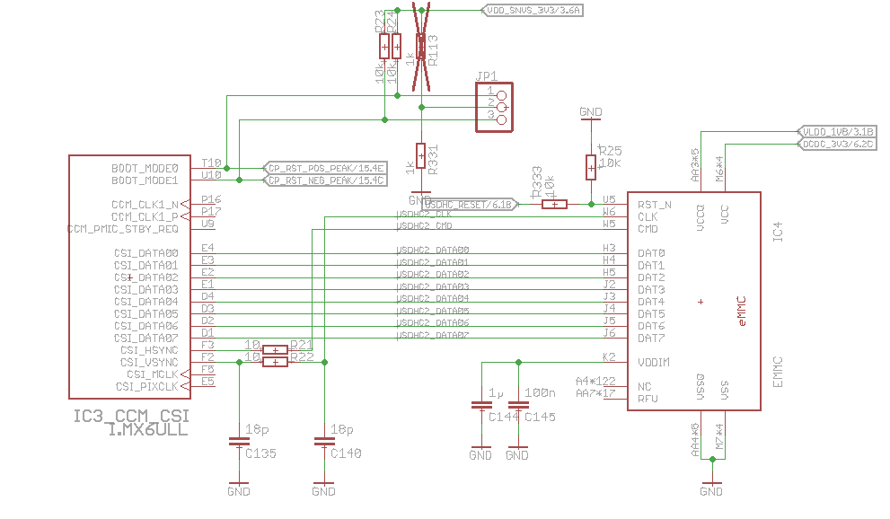
- Mark as New
- Bookmark
- Subscribe
- Mute
- Subscribe to RSS Feed
- Permalink
- Report Inappropriate Content
Hi Stefan
one can try to adjust drive strength settings in pads associated
with problematic bits: SW_PAD_CTL_PAD_x_x SW PAD Control
Registers, Chapter 32 IOMUX Controller (IOMUXC) i.MX6ULL Reference Manual
http://www.nxp.com/docs/en/reference-manual/IMX6ULLRM.pdf
and control waveforms with oscilloscope.
Best regards
igor
-----------------------------------------------------------------------------------------------------------------------
Note: If this post answers your question, please click the Correct Answer button. Thank you!
-----------------------------------------------------------------------------------------------------------------------
- Mark as New
- Bookmark
- Subscribe
- Mute
- Subscribe to RSS Feed
- Permalink
- Report Inappropriate Content
I tried the following settings, but the bit errors stays:
SDHCI frequency | DT PAD control | DSE
200 MHz | 170F9 | RO / 7
200 MHz | 170F1 | RO / 6
200 MHz | 170C9 | RO
50 MHz | 17079 | RO / 7
50 MHz | 17049 | RO
Could this be a clock domain crossing issue?
- Mark as New
- Bookmark
- Subscribe
- Mute
- Subscribe to RSS Feed
- Permalink
- Report Inappropriate Content
most likely this may be noise coupling issue. Is it working at lower frequencies?
Also may be useful to check layout, described in sect.3.6.8 High speed signal routing recommendations
i.MX6 System Development User’s Guide
https://www.nxp.com/docs/en/user-guide/IMX6DQ6SDLHDG.pdf
All synchronous modules should have bus length matching and relative clock length control.
— For SD module interfaces:
– Match data and CMD trace lengths (length delta depends on bus rates)
– CLK should be longer than the longest signal in the Data/CMD group (+5 mils)
— Similar DDR rules must be followed for data, address and control as for SD module interfaces.
Best regards
igor
- Mark as New
- Bookmark
- Subscribe
- Mute
- Subscribe to RSS Feed
- Permalink
- Report Inappropriate Content
After fixing a probing issue of the sdhci driver for 1.8V only signal voltage, i was able to reduce the clock frequency:
After removing the pinctrl settings for 100MHz and 200MHz state in DT:
clock: 52000000 Hz
actual clock: 33000000 Hz
vdd: 21 (3.3 ~ 3.4 V)
bus mode: 2 (push-pull)
chip select: 0 (don't care)
power mode: 2 (on)
bus width: 2 (4 bits)
timing spec: 8 (mmc DDR52)
signal voltage: 0 (1.80 V)
After additionaling setting the max-frequency to 20 MHz via DT:
clock: 20000000 Hz
actual clock: 16500000 Hz
vdd: 21 (3.3 ~ 3.4 V)
bus mode: 2 (push-pull)
chip select: 0 (don't care)
power mode: 2 (on)
bus width: 2 (4 bits)
timing spec: 8 (mmc DDR52)
signal voltage: 0 (1.80 V)
In both cases the issue still occured.- Mark as New
- Bookmark
- Subscribe
- Mute
- Subscribe to RSS Feed
- Permalink
- Report Inappropriate Content
please use logic analyzer and try to find source of error
mmc_compare_ext_csds() fails with error code -84 (EBADMSG), use
waveforms and descriptions in mmc specification JESD84-B50.
Also one can try with i.MX6ULL EVK.
Best regards
igor
- Mark as New
- Bookmark
- Subscribe
- Mute
- Subscribe to RSS Feed
- Permalink
- Report Inappropriate Content
also one can test 8 bit mode in uboot:
uboot/board/freescale/mx6ullevk/mx6ullevk.c
use
#define CONFIG_MX6ULL_EVK_EMMC_REWORK