
- Forums
- Product Forums
- General Purpose MicrocontrollersGeneral Purpose Microcontrollers
- i.MX Forumsi.MX Forums
- QorIQ Processing PlatformsQorIQ Processing Platforms
- Identification and SecurityIdentification and Security
- Power ManagementPower Management
- Wireless ConnectivityWireless Connectivity
- RFID / NFCRFID / NFC
- Advanced AnalogAdvanced Analog
- Neural Processing UnitsNeural Processing Units
- MCX Microcontrollers
- S32G
- S32K
- S32V
- MPC5xxx
- Other NXP Products
- S12 / MagniV Microcontrollers
- Powertrain and Electrification Analog Drivers
- Sensors
- Vybrid Processors
- Digital Signal Controllers
- 8-bit Microcontrollers
- ColdFire/68K Microcontrollers and Processors
- PowerQUICC Processors
- OSBDM and TBDML
- S32M
- S32Z/E
-
- Solution Forums
- Software Forums
- MCUXpresso Software and ToolsMCUXpresso Software and Tools
- CodeWarriorCodeWarrior
- MQX Software SolutionsMQX Software Solutions
- Model-Based Design Toolbox (MBDT)Model-Based Design Toolbox (MBDT)
- FreeMASTER
- eIQ Machine Learning Software
- Embedded Software and Tools Clinic
- S32 SDK
- S32 Design Studio
- GUI Guider
- Zephyr Project
- Voice Technology
- Application Software Packs
- Secure Provisioning SDK (SPSDK)
- Processor Expert Software
- Generative AI & LLMs
-
- Topics
- Mobile Robotics - Drones and RoversMobile Robotics - Drones and Rovers
- NXP Training ContentNXP Training Content
- University ProgramsUniversity Programs
- Rapid IoT
- NXP Designs
- SafeAssure-Community
- OSS Security & Maintenance
- Using Our Community
-
- Cloud Lab Forums
-
- Knowledge Bases
- ARM Microcontrollers
- i.MX Processors
- Identification and Security
- Model-Based Design Toolbox (MBDT)
- QorIQ Processing Platforms
- S32 Automotive Processing Platform
- Wireless Connectivity
- CodeWarrior
- MCUXpresso Suite of Software and Tools
- MQX Software Solutions
- RFID / NFC
- Advanced Analog
- Neural Processing Units
-
- NXP Tech Blogs
- Home
- :
- i.MX Forums
- :
- i.MX Processors
- :
- Re: Using two parallel TV decoders connected to two CSI ports on IMX6Q
Using two parallel TV decoders connected to two CSI ports on IMX6Q
- Subscribe to RSS Feed
- Mark Topic as New
- Mark Topic as Read
- Float this Topic for Current User
- Bookmark
- Subscribe
- Mute
- Printer Friendly Page

- Mark as New
- Bookmark
- Subscribe
- Mute
- Subscribe to RSS Feed
- Permalink
- Report Inappropriate Content
Hello,
We are trying to use two TVP5150 decoders on our custom board connected to CSI0-IPU0 and CSI1-IPU1 respectively. Source signal for both decoders comes from two PAL cameras. The CSI0-IPU0 works good, tested with tvin and overlay unit tests (though I had to manually set input height to 576 to get proper vsync in overlay test). Below is a screenshot from running overlay unit test on CSI0-IPU0 path from first TVP5150:
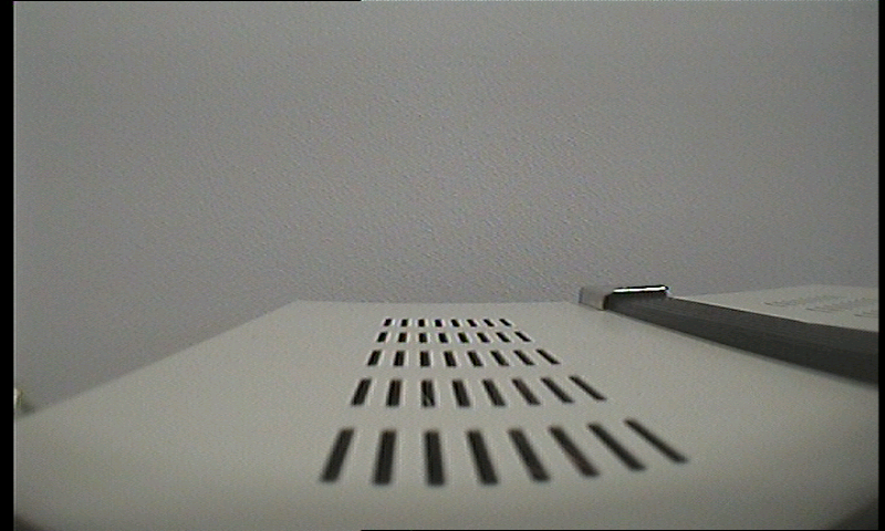
As you can see the image is ok, apart from some horizontal and vertical blank pixels .
Using the same driver we tried to test CSI1-IPU1 path, and this is the result:
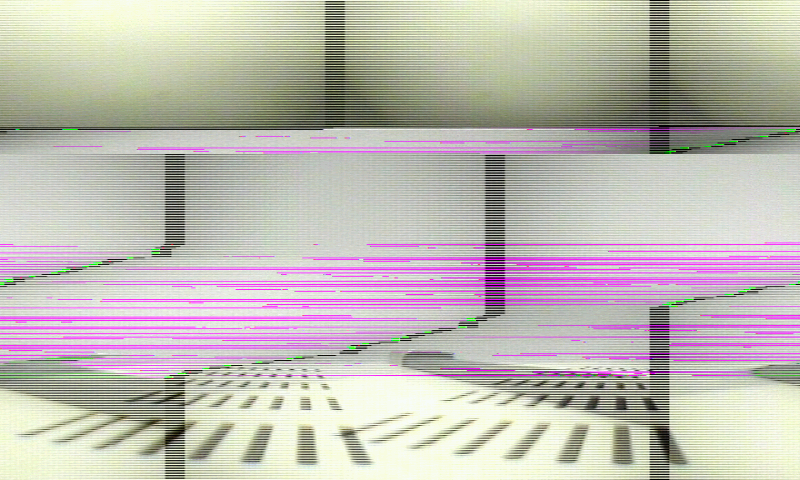
The capture is both not hsynced and vsynced (scrolling in both axes). There are also some green and purple lines showing up. To be sure that secondary TVP5150 output signal is correct we disabled first decoder chip from CSI0-IPU0 path and connected digital outputs from CSI1-IPU1 path decoder to CSI0-IPU0 inputs and image was OK (like on first screenshot). Since we are using BT.656 mode in decoder/mxc_v4l2_capture we can assume pins are muxed correctly (since IPU detects EAV nad SAV properly). This leads me to believe problem must be on mxc_v4l2_capture or IPU driver side.
Documentation shows only CSI0-IPU0 and CSI-MIPI examples, also searching here gave no reports of working CSI1-IPU1 parallel cameras/tv decoders. There was one attempt to have working double tvp5150 on imx53 but that chip has only one IPU and does not support two simultaneous cameras running. According to sources I gathered the imx6q should be able to handle two simultaneous parallel CSI cameras since it has two IPUs.
We are basing our code on 1.1.0 BSP but I backported IPU and v4l changes from 4.0.0 release to our codebase and still same result. Did anyone get dual parallel CSI cameras/tv decoders working on IPU0 and IPU1? Any help would be great and useful to the community since apparently I am not the only one having problems with CSI1+IPU1.
Solved! Go to Solution.
- Mark as New
- Bookmark
- Subscribe
- Mute
- Subscribe to RSS Feed
- Permalink
- Report Inappropriate Content
It seems we discovered the way to fix this problem. Previously our bootargs contained only mxcfb0 parameters for our LDB based display. At some point we tried to test HDMI output from our custom board, added HDMI parameters for mxcfb1 in our bootargs and the problem magically got solved...
We still do not know what was actually causing this in the code but at least the issue is gone.
- Mark as New
- Bookmark
- Subscribe
- Mute
- Subscribe to RSS Feed
- Permalink
- Report Inappropriate Content
Hello,
I'm trying to use tvp5150 as pal decoder. It is connected to CSI0.
I have done the tvp5150 driver starting from the adv7180 one: device is probed at board startup and I can read/write registers on I2C bus.
The problem is that when I do "cat /dev/video0" I have no data output: cat: read error: Timer expired, ERROR: v4l2 capture: mxc_v4l_read timeout counter 0.
I have tried both embedded sync and external HSYNC/VSYNC, but with no luck.
I have also tried to change SENS_CONF in order to test all HSYNC/VSYNC/DATA/CLOCK polarity combinations.
Please could you share your source code ?
Did you connect HSYNC/VSYNC or did you use embedded sync ?
What is the value of your SENS_CONF register (0x2630000) ?
Thanks in advance for any help.
Angelo
- Mark as New
- Bookmark
- Subscribe
- Mute
- Subscribe to RSS Feed
- Permalink
- Report Inappropriate Content
It seems we discovered the way to fix this problem. Previously our bootargs contained only mxcfb0 parameters for our LDB based display. At some point we tried to test HDMI output from our custom board, added HDMI parameters for mxcfb1 in our bootargs and the problem magically got solved...
We still do not know what was actually causing this in the code but at least the issue is gone.

- Mark as New
- Bookmark
- Subscribe
- Mute
- Subscribe to RSS Feed
- Permalink
- Report Inappropriate Content
Yes, as Kamil said, the issue is gone, but the true reason is still unknown. What is interesting, we do not need to connect the HDMI/DVI display at all, but for some reason the configuration data for mxcfb1 is needed by the drivers during initialization. After dumping both IPUs configuration registers we did not see any significant difference, and probably it is somewhere we have not looked at yet :smileyhappy: I suppose that Freescale team is working on the issue, so maybe our findings can be helpful for us all.
- Mark as New
- Bookmark
- Subscribe
- Mute
- Subscribe to RSS Feed
- Permalink
- Report Inappropriate Content
I'm trying to do similar things, to get two TVP5150AM work with IPU1/CSI0 and IPU2/CSI1, is it possible for you to share the patch on that portion?
I'm using LTIB 4.1.0 and so far can only get one TVP5150AM(IPU1/CSI0) work.
Thanks!
- Mark as New
- Bookmark
- Subscribe
- Mute
- Subscribe to RSS Feed
- Permalink
- Report Inappropriate Content
Update:
I tried switching around CSI_MEM channels in ipu_csi_enc.c for secondary csi/ipu pair but still same effect. I tried CSI -> IC -> MEM path and it seems to have proper hsync but still not vsynced and green/purple lines still do appear. Problem still is not solved.
By the way: Those green lines appear even if I switch off camera input to the decoder. At this point I am not sure if those are artifacts introduced by IPU or is it something overwriting the double-buffer memory.

- Mark as New
- Bookmark
- Subscribe
- Mute
- Subscribe to RSS Feed
- Permalink
- Report Inappropriate Content
The purple and green color noise is often a sign of a noisy pixel clock especially when it starts and stops in mid line as your test image shows. I've seen very similar distortion when we had a signal integrity problem on a board that caused a non-monoticity on the pixel clock line. The non-monoticity sometimes looked like an extra clock edge to the CSI and so it clocked the same sample in twice. BT.656 data arrives as interleaved YUV422 which is a luminance sample follow by either an R or B chrominance sample (YUYVYUYV....). The extra false clock caused two problems: 1) synchronization was lost because the row is shifted over 2) the luminance and chrominance channels become swapped (causing the purple lines which end in green). The next time a false clock occurs the extra sample fixes the luminance/chrominance swap and you can see this in some of the lines where the purple starts and then stops.
In our case, when I used regular oscilloscope probe to examine the pixel clock, the capacitance of the probe (about 13 pF) was enough to filter out the non-monoticity and the image cleared up as soon as I touched the probe to the clock line. Using an acitve (low capacitance probe) I was able to see non-monoticity that was messing up the image. We were able to fix the signal integrity issue on the next board layout by adding some termination.
The other thing that may cause this type of noise is pixel clock polarity (check the SENS_PIX_CLK_POL for CSI1). Clocking the sample in on the wrong clock edge can cause sync problems because the SAV/EAV codes may be corrupt. It could also cause color noise if the data lines from the previous sample have not settled.
Finally, I noticed that the test image you posted has interlacing noise (the light/dark combing effect) and the two fields are not combined. Your PAL camera will produce interlaced video which the TVP5150 will send over the BT.656 link as Field0 followed by Field1. It looks as though the de-interlacer (VDIC) is not in the path for CSI1-IPU1.
I hope some of this is helpful.
- Mark as New
- Bookmark
- Subscribe
- Mute
- Subscribe to RSS Feed
- Permalink
- Report Inappropriate Content
Thank you for the reply!
Pixel clock seems to be alright (it was also tested before when we cross-connected decoders to different CSI-IPU inputs). Nothing unusual found using the o-scope.
I tried changing clock polarity and odd thing is that changing it had no visible results even when done for CSI0/IPU0. With inverted clock polarity CSI0/IPU0 image was still good and CSI1/IPU1 still distorted.
Regarding video being interlaced - you are right. It seems default CSI -> MEM path for CSI1/IPU1 has no deinterlacing done. I forgot to mention this earlier but using CSI -> IC -> MEM path for CSI1/IPU1 gives deinterlaced video and good hsync (but still same green/purple distortions are present in the image).
One additional note is that those green lines (which become purple when picture in the background is closer to white than to black) appear on the whole screen (not just the middle) and they seem to be scrolling from top to bottom of the screen. Even if I force TVP5150 to output black screen (value 0x08 in register 0x00) those green lines are still scrolling in the image.
To sum it up it seems that CSI1-IPU1 receives correct, undistorted signal and distortion happens somewhere on the ipu hw/driver level.
- Mark as New
- Bookmark
- Subscribe
- Mute
- Subscribe to RSS Feed
- Permalink
- Report Inappropriate Content
I also find it interesting that changing the pixel clock polarity did not change anything. I guess that means that the output hold time (which is speced at 2ns minimum on the TVP5150) is sufficient to still clock in the correct values.
So with the IC (and therefore the VDIC) in the path it sounds like you are pretty close. Here are few more things to try that might help you find the issue:
1. If you are seeing green when the TVP5150 is configured to output black then the sample order seems messed up. For black the TVP5150 outputs YUV422 as Y=0x10 and U,V=0x80. With these swapped Y=0x80 and U,V=0x10 you get green. Just as a test try the following pixel formats for the CSI to see if any of them give you black video when TVP5150 is set to output black:
V4L2_PIX_FMT_YUYV
V4L2_PIX_FMT_YVYU
V4L2_PIX_FMT_UYVY (probably what should be used with tvp5150)
V4L2_PIX_FMT_VYUY
2. The CSI uses the following registers when it interprets that SAV/EAV codes: CCIR_PRECOM, CCIR_CODE_1, CCIR_CODE_2 and CCIR_CODE_3. It would be worth checking that they contain the same values as CSI0.
3. Try putting CSI1 in to test mode. This will cause it to generate a chess board test pattern regardless of the input (see CSI1_TST_CTRL register). That register will also let you control the RGB value of the even pixels. If this works and you get a stable image with the color you expect on the even pixels it means that the IPU path past the CSI (ie. IC, VDIC and IDMAC) are all configured correctly. That would put your problem with the CSI config, TV5150 config or output, or possibly still an SI problem on your board between the connector and the MX6 (something that would not change even if you cross connect your 5150s).
4. You've probably already done this but while capture is running dump all CSI1 registers and then review them to make sure they all make sense. Even better would be to first dump all CSI0 regs from the working video path and compare them to CSI1.
Good luck, I hope you find the root cause soon.
Don
- Mark as New
- Bookmark
- Subscribe
- Mute
- Subscribe to RSS Feed
- Permalink
- Report Inappropriate Content
Hello,
Running IPU and in particular IPU_CSI register dumps gives no evidence of faulty configuration (apart from CSI0_ACT_FRM_SIZE being set for IPU1 while remaining CSI0 registers are 0 as they should be, this does not happen for IPU0 - the CSI1_ACT_FRM_SIZE in that case is 0).
I made the chessboard test for both IPU0 and IPU1 and results were interesting: in both cases chessboard is stable and displays correct colors for even squares... but for odd squares they are white instead of black (as is specified in the reference manual). When I set the test generator to output R=0xFF G=0xFF B=0xFF even fields are white as expected (and black for 0x00). Right now I do not understand this behavior, if this was error in the SW then even fields would not display white when FFs were set for all RGB values. Error in documentation I guess? Or some misunderstanding on my side. You can see the result in the screenshot below:

So to sum it up, chessboard test passes for both IPU0 and IPU1 (apart from white fields). Register dump from tests with TVP5150 decoder (not a chessboard test dump) included as files, maybe this will help. Interesting thing is that even for dump2.txt where secondary IPU was tested at some point there were logs from IPU0 (I mean those dma related messages). Our framebuffer device is using IPU1 if this is any help to the case.
I have also tried changing YUV format but unfortunately no good results.
