
- Forums
- Product Forums
- General Purpose MicrocontrollersGeneral Purpose Microcontrollers
- i.MX Forumsi.MX Forums
- QorIQ Processing PlatformsQorIQ Processing Platforms
- Identification and SecurityIdentification and Security
- Power ManagementPower Management
- Wireless ConnectivityWireless Connectivity
- RFID / NFCRFID / NFC
- Advanced AnalogAdvanced Analog
- Neural Processing UnitsNeural Processing Units
- MCX Microcontrollers
- S32G
- S32K
- S32V
- MPC5xxx
- Other NXP Products
- S12 / MagniV Microcontrollers
- Powertrain and Electrification Analog Drivers
- Sensors
- Vybrid Processors
- Digital Signal Controllers
- 8-bit Microcontrollers
- ColdFire/68K Microcontrollers and Processors
- PowerQUICC Processors
- OSBDM and TBDML
- S32M
- S32Z/E
-
- Solution Forums
- Software Forums
- MCUXpresso Software and ToolsMCUXpresso Software and Tools
- CodeWarriorCodeWarrior
- MQX Software SolutionsMQX Software Solutions
- Model-Based Design Toolbox (MBDT)Model-Based Design Toolbox (MBDT)
- FreeMASTER
- eIQ Machine Learning Software
- Embedded Software and Tools Clinic
- S32 SDK
- S32 Design Studio
- GUI Guider
- Zephyr Project
- Voice Technology
- Application Software Packs
- Secure Provisioning SDK (SPSDK)
- Processor Expert Software
- Generative AI & LLMs
-
- Topics
- Mobile Robotics - Drones and RoversMobile Robotics - Drones and Rovers
- NXP Training ContentNXP Training Content
- University ProgramsUniversity Programs
- Rapid IoT
- NXP Designs
- SafeAssure-Community
- OSS Security & Maintenance
- Using Our Community
-
- Cloud Lab Forums
-
- Knowledge Bases
- ARM Microcontrollers
- i.MX Processors
- Identification and Security
- Model-Based Design Toolbox (MBDT)
- QorIQ Processing Platforms
- S32 Automotive Processing Platform
- Wireless Connectivity
- CodeWarrior
- MCUXpresso Suite of Software and Tools
- MQX Software Solutions
- RFID / NFC
- Advanced Analog
- Neural Processing Units
-
- NXP Tech Blogs
- Home
- :
- Product Forums
- :
- S32K
- :
- Re: Input PWM is zero for SDK
Input PWM is zero for SDK
- Subscribe to RSS Feed
- Mark Topic as New
- Mark Topic as Read
- Float this Topic for Current User
- Bookmark
- Subscribe
- Mute
- Printer Friendly Page
- Mark as New
- Bookmark
- Subscribe
- Mute
- Subscribe to RSS Feed
- Permalink
- Report Inappropriate Content
Hello Community
We want to detect the Crash signal input and configure it according to the example, but there is no return value of IC_GETMEASUREMENT (), please help us to check whether we made a mistake in the configuration.
Chip version:S32K148 -> 144
PIN: PTD18
Hardware environment: SRS analog input
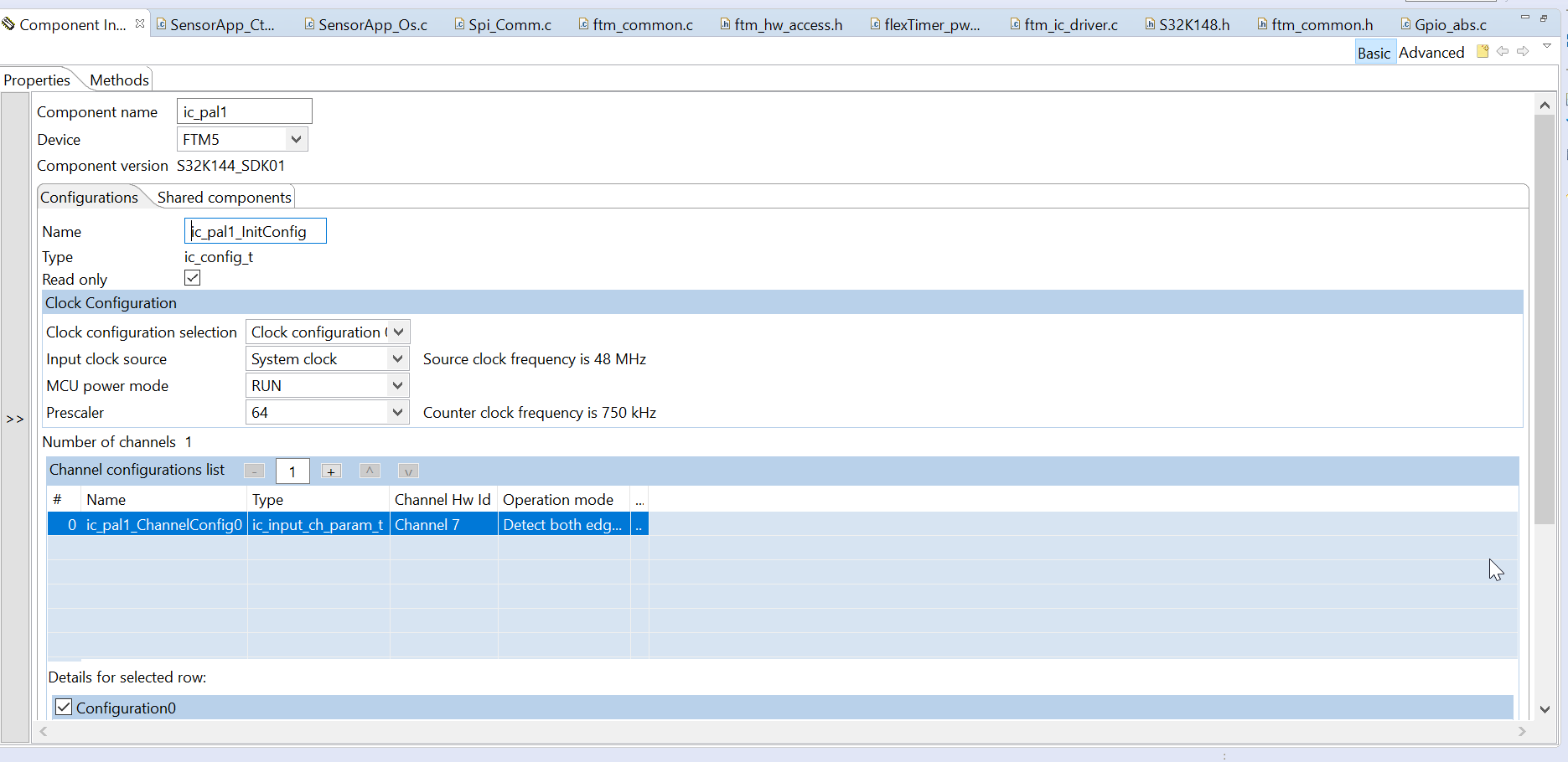
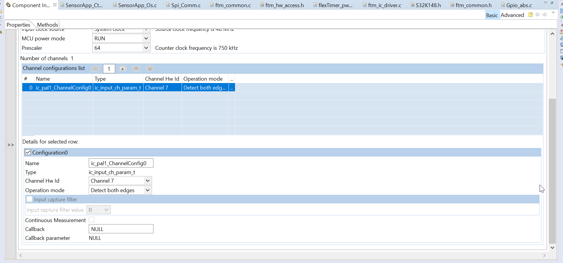
Config: FTM5_CH7
for example: ic_pal_s32k148
MCU detects CRASH signal input,
uint16_t inputCaptureMeas = 0U;
uint16_t inputMeas = 0U;
uint32_t frequency;
uint8_t channel = ic_pal1_ChnConfig->hwChannelId;
IC_Init(&ic_pal1_instance, &ic_pal1_InitConfig);
while(1)
{
frequency = FTM_DRV_GetFrequency(ic_pal1_instance.instIdx);
inputCaptureMeas = IC_GetMeasurement(&ic_pal1_instance, channel);
inputMeas = frequency / (inputCaptureMeas);
JPCC_DEBUG(JPCC_LOG_LEVEL_WARNING, "[ SensorApp] 6 PWM uFrequencyHZ=[%lu], frequency=[%lu], inputCaptureMeas=[%u], inputMeas=[%lu]\r\n",
flexTimer_pwm1_PwmConfig.uFrequencyHZ, frequency, inputCaptureMeas, inputMeas);
OS_sleep(300);
};
Solved! Go to Solution.
- Mark as New
- Bookmark
- Subscribe
- Mute
- Subscribe to RSS Feed
- Permalink
- Report Inappropriate Content
Hi,
Looking at the screenshots you posted, I see the FTM frequency is set to 256Hz.
The resolution is therefore 1/256 = 3.9ms
3.9ms * 28 = 109.2ms which is 91% of 120ms.
If you need to have a higher resolution, you need to set a higher FTM frequency.
Regards,
Daniel
- Mark as New
- Bookmark
- Subscribe
- Mute
- Subscribe to RSS Feed
- Permalink
- Report Inappropriate Content
The signal input frequency we use is as shown in "crah.jpg",I don't know how to calculate the duty cycle according to them. Could you please give me a calculation method or formula?
- Mark as New
- Bookmark
- Subscribe
- Mute
- Subscribe to RSS Feed
- Permalink
- Report Inappropriate Content
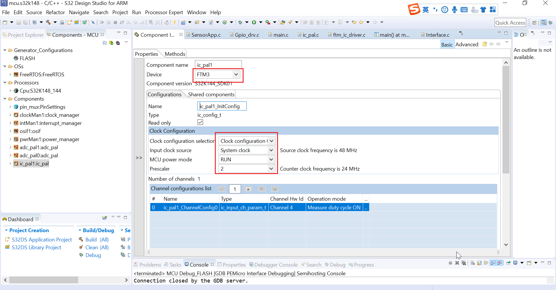
Configuration changes
PIN: PTC10
Hardware environment: SRS analog input
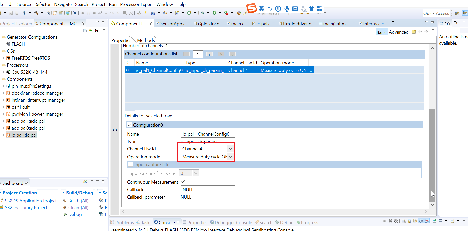
Config: FTM3_CH4
The current configuration has SRS input.
We would like to know how to calculate the duty cycle. Could you provide a specific calculation formula?
6148 = IC_GetMeasurement(&ic_pal1_instance, channel);
duty = 40%.
- Mark as New
- Bookmark
- Subscribe
- Mute
- Subscribe to RSS Feed
- Permalink
- Report Inappropriate Content
Hi,
The IC_GetMeasurement() function returns the duty-cycle value in FTM3 ticks (24MHz).
If you know the period of the input signal, you can easily calculate the duty-cycle in %.
Regards,
Daniel
- Mark as New
- Bookmark
- Subscribe
- Mute
- Subscribe to RSS Feed
- Permalink
- Report Inappropriate Content
Our input signal (Type)
T = 120ms.
Hz = 0.0083333333333KHz
How do we use the data we have to calculate the duty cycle?Could you give me an example? Thank you
- Mark as New
- Bookmark
- Subscribe
- Mute
- Subscribe to RSS Feed
- Permalink
- Report Inappropriate Content
Hi,
The IC_GetMeasurement() function returns number of FTM ticks measured while the input signal is ON.
One FTM tick is one period of the FTM function clock.
Instead of the PAL driver, you can use the FTM_IC driver.
Example: ftm_signal_measurement_s32k148
With this configuration:

The driver can measure input signal:

If you need to measure signal of frequency 8.33Hz, you need to select a slower FTM clock.
For example,


In this case, 1 FTM clock cycle = 1 FTM tick = 1/62500 = 16us is resolution of the measurement.
You could use faster FTM clock frequency but you would need to count the FTM overflows and add it to the time captured between the two edges.
Regards,
Daniel
- Mark as New
- Bookmark
- Subscribe
- Mute
- Subscribe to RSS Feed
- Permalink
- Report Inappropriate Content
Our input signal (Type)
T = 120ms.
Hz = 0.0083333333333KHz
Duty = 90%
FTM_DRV_GetInputCaptureMeasurement(INST_FLEXTIMER_IC1, 4U) = 28;
1 FTM clock cycle = 1 FTM tick = 1/62500 = 16us is resolution of the measurement.
Duty cycle calculation formula: (28 * 16us) / 120ms = 90%
Is that the calculation?
Could you specify the duty cycle calculation formula with the above parameters.


- Mark as New
- Bookmark
- Subscribe
- Mute
- Subscribe to RSS Feed
- Permalink
- Report Inappropriate Content
Hi,
Looking at the screenshots you posted, I see the FTM frequency is set to 256Hz.
The resolution is therefore 1/256 = 3.9ms
3.9ms * 28 = 109.2ms which is 91% of 120ms.
If you need to have a higher resolution, you need to set a higher FTM frequency.
Regards,
Daniel
- Mark as New
- Bookmark
- Subscribe
- Mute
- Subscribe to RSS Feed
- Permalink
- Report Inappropriate Content
Hello,
Could you please attach the project?
The issue could be in the PIN driver, for example.
Can you scope the signal on PTD18?
Thank you,
BR, Daniel
- Mark as New
- Bookmark
- Subscribe
- Mute
- Subscribe to RSS Feed
- Permalink
- Report Inappropriate Content