
- Forums
- Product Forums
- General Purpose MicrocontrollersGeneral Purpose Microcontrollers
- i.MX Forumsi.MX Forums
- QorIQ Processing PlatformsQorIQ Processing Platforms
- Identification and SecurityIdentification and Security
- Power ManagementPower Management
- Wireless ConnectivityWireless Connectivity
- RFID / NFCRFID / NFC
- Advanced AnalogAdvanced Analog
- Neural Processing UnitsNeural Processing Units
- MCX Microcontrollers
- S32G
- S32K
- S32V
- MPC5xxx
- Other NXP Products
- S12 / MagniV Microcontrollers
- Powertrain and Electrification Analog Drivers
- Sensors
- Vybrid Processors
- Digital Signal Controllers
- 8-bit Microcontrollers
- ColdFire/68K Microcontrollers and Processors
- PowerQUICC Processors
- OSBDM and TBDML
- S32M
- S32Z/E
-
- Solution Forums
- Software Forums
- MCUXpresso Software and ToolsMCUXpresso Software and Tools
- CodeWarriorCodeWarrior
- MQX Software SolutionsMQX Software Solutions
- Model-Based Design Toolbox (MBDT)Model-Based Design Toolbox (MBDT)
- FreeMASTER
- eIQ Machine Learning Software
- Embedded Software and Tools Clinic
- S32 SDK
- S32 Design Studio
- GUI Guider
- Zephyr Project
- Voice Technology
- Application Software Packs
- Secure Provisioning SDK (SPSDK)
- Processor Expert Software
- Generative AI & LLMs
-
- Topics
- Mobile Robotics - Drones and RoversMobile Robotics - Drones and Rovers
- NXP Training ContentNXP Training Content
- University ProgramsUniversity Programs
- Rapid IoT
- NXP Designs
- SafeAssure-Community
- OSS Security & Maintenance
- Using Our Community
-
- Cloud Lab Forums
-
- Knowledge Bases
- ARM Microcontrollers
- i.MX Processors
- Identification and Security
- Model-Based Design Toolbox (MBDT)
- QorIQ Processing Platforms
- S32 Automotive Processing Platform
- Wireless Connectivity
- CodeWarrior
- MCUXpresso Suite of Software and Tools
- MQX Software Solutions
- RFID / NFC
- Advanced Analog
- Neural Processing Units
-
- NXP Tech Blogs
- Home
- :
- Model-Based Design Toolbox (MBDT)
- :
- Model-Based Design Toolbox (MBDT)
- :
- Re: Pwm_delay_in_trigger_pulse
Pwm_delay_in_trigger_pulse
- Subscribe to RSS Feed
- Mark Topic as New
- Mark Topic as Read
- Float this Topic for Current User
- Bookmark
- Subscribe
- Mute
- Printer Friendly Page

- Mark as New
- Bookmark
- Subscribe
- Mute
- Subscribe to RSS Feed
- Permalink
- Report Inappropriate Content
Hello NXP team,
Currently we are generating the pwm pulse for two channels.
and with pwm channel 1 pulse, we are triggering the pwm channel 2 pulse with edge triggering.

but with triggering, there is some delay in Pwm channel 2 pulse and that delay is not constant it is getting varying from one pulse to another pulse.
Photo - 1: 820uS delay for pwm 2.

Photo - 2: no delay for pwm 2.

Photo - 3: 520uS delay for pwm 2.

we don't know how to reduce this delay, and it is not constant delay.
We have attached the configuration settings for this pwm pulse below,
Emios_0 - Channel_0 for pwm2 pulse


Emios_1 - Channel_0 for pwm1 pulse


Mcl_configuration for Pwm2 pulse

Kindly help us to resolve this issue related to pwm delay.
Thanks, and regards,
Esakki.P
@Irina_Costachescu @dragostoma
Solved! Go to Solution.
 stefanvlad
- Mark as New
- Bookmark
- Subscribe
- Mute
- Subscribe to RSS Feed
- Permalink
- Report Inappropriate Content
Hi @Vijay98 ,
I'm not sure what do you mean having an issue on PTC10, since on this thread Re: Pwm_delay_in_trigger_pulse - NXP Community, the solution works well and tested on logic analyzer.
Can you provide pictures of the model that you modified based on the steps i provided in the thread above, instead of reposting my screenshots.
Once again to use another pin to output the signal from PTA3 to PTC10 there are only two options, one is presented above by using PTC10 as emios_0_ch6 and the other solution is to use PTC10 as lcu1_out11:

Then you need to route the signal from PTA3 (lcu0_out2) to PTC10 (lcu1_out11) using TRGMUX:

Then we need to update the LCU configuration for the new input:
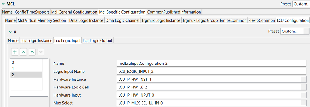
And then we update the LCU output config:
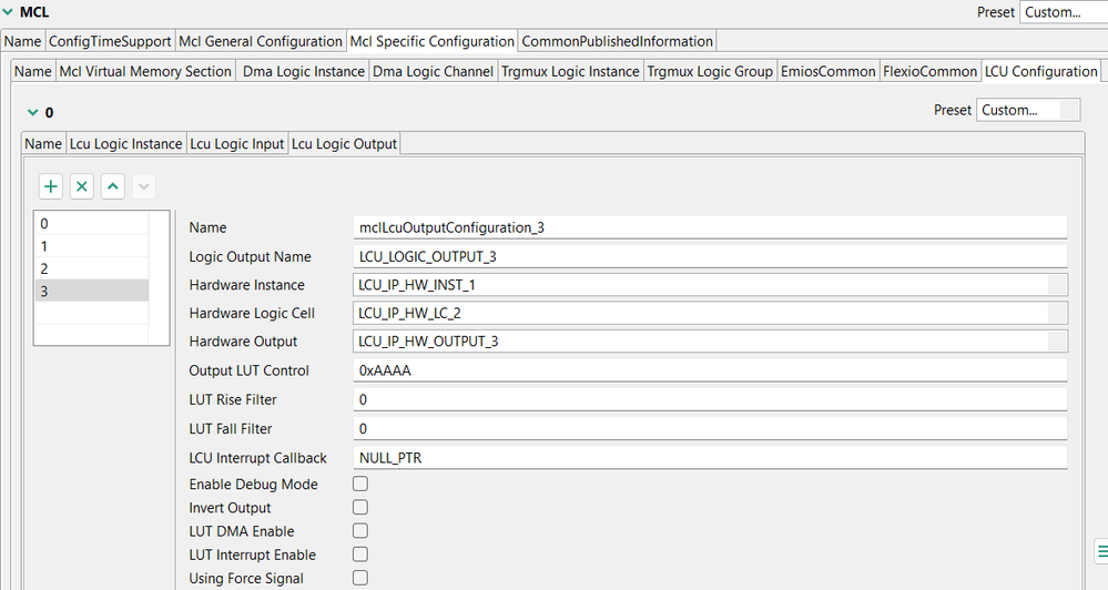
Also PTC10 pin needs to be added into the Port peripheral:

and the last step is to update the model with the new LCU output:

After this, clean up the local Matlab folder, delete the .slxc file, and the folders 32k312_pwm_lcu_mod_carrier_s32ct_ert_rtw, and slprj:

Then rebuild and flash the project on the S32K312 board, and check the pins with logic analyzer:

And to summarize the complete application, how all the peripherals are connected, I have created this diagram:

This are all the steps needed, please read them carefully and replicate them on your model,
Best regards,
Stefan V.
 dragostoma
- Mark as New
- Bookmark
- Subscribe
- Mute
- Subscribe to RSS Feed
- Permalink
- Report Inappropriate Content
Hi, @Vijay98,
First of all, for the results obtained and the displayed delay, were the recommendations from this post also taken into account, namely those related to the level of optimization?
Secondly, I would like to mention the fact that I noticed in the provided screenshots the configuration of a master bus in the MCL component, for the eMIOS 1 instance.

On the other hand, in the configuration of the PWM channel I notice that in the same eMIOS 1 instance it is set to use a internal counter, that is, the reference to the previously mentioned master bus is not taken into account, but the calculation is based on an internal counter.

Is this how the application was designed? Because the results of the calculations are totally different regarding the counter used, if it is internal or external. In the case of an external master bus, when calculating the frequency and period of a PWM signal, the period of the master bus, the clock divider and respectively the master bus prescalers are also included. Conversely, these things do not apply to the use of an internal counter.
The last question would be if this model uses the same configuration as in the other similar thread, because in order to fully understand the behavior and configuration of the application, it can't help to share the configuration project, along with the model.
Let us know about your progress.
Best regards,
Dragos
- Mark as New
- Bookmark
- Subscribe
- Mute
- Subscribe to RSS Feed
- Permalink
- Report Inappropriate Content
Hello Dragos,
My first point is that
Yes, we are generating the pwm signal using the internal counter for emios1_ch0 and emios0_ch0 in OPWFMB mode. And in mcl configuration we mentioned only clock divider value.
And yes, we are configuring the same configuration for pwm in this post Re: Reg: Raising edge and Falling edge detection issue_S32k344 - NXP Community.
We can be able to check the pwm edge triggering and able to generate pwm2 pulse within the pwm1 pulse on time.
But currently we are facing an issue of Certain delay in pwm2, and that delay is not constant for pwm2 pulse.
Photo - 1: 820uS delay for pwm 2.

Photo - 2: no delay for pwm 2.

Photo - 3: 520uS delay for pwm 2.

We don't know how to reduce this delay or make it as a constant delay.
Kindly help us resolve this issue.
I have attached the model and configuration with this post.
Thanks & regards,
Esakki.P
stefanvlad
- Mark as New
- Bookmark
- Subscribe
- Mute
- Subscribe to RSS Feed
- Permalink
- Report Inappropriate Content
Hi @Vijay98 ,
I have opened the archived model:

And flashed it on the S32K312EVB-Q172 board, then connected Logic analyzer probes and got this signals:

Unfortunately the PTC10 signal seems to be reversed from your "Photo - 2: no delay for pwm 2."

But nevertheless i understood want you want to achieve, an PWM signal with lower Frequency , usually called a PWM_Modulator and a signal with a higher (11x) frequency, called a PWM_Carrier.
there are two approaches to do this:
- Software enable/disable of PWM_Carrier on the triggered PWM_Modulator interrupt, this is the implementation that you have tried. The disadvantage is the delay is not constant as you saw, one way to correct this is to check the peripheral priorities in the Interrupt Controller, another way is to implement the FastUpdate function for PWM, we have an example in the model s32k344_mc_bldc_s32ct:
-
Hardware generation of the PWM_Carrier, to be generated using the eMIOS with TRGMUX and LCU:
With this configuration i was able to generate the proper PWM signals:
This approach is a bit more complex, but it will ensure the delay is minimum and controllable.


Please try the FastUpdatePWM implementation in your model, or you can test the attached model in s32k312_pwm_lcu_s32ct.zip:

Let me know if this helps you and have a great weekend,
Stefan V.
- Mark as New
- Bookmark
- Subscribe
- Mute
- Subscribe to RSS Feed
- Permalink
- Report Inappropriate Content
Hello, @stefanvlad
1. For the first approach, Fast update function we tried with fast update function in our model and checked but there is a variable delay in pwm 2 pulse. is there any example model available for the previous mentioned requirement.
and i have attached the file "Test_in_new".

2. And for the second approach,
The program which shared was running in opwmb and has counter bus of bcde. And we seen change in periods not happening, its in fixed frequency with variable dutycycle.
Observation with your shared model(S32k312_pwm_icu_S32ct):
1. High side frequency always at 259.63HZ, refer image.
(our requirement: it need to change from 0.1HZ to 150HZ)
2. Low side Frequency always at 2.8Khz refer image
(Our requirement: its need to change from 0.1Hz to 12Khz based on ON time of High side frequency)

we tried changing the mode and counter bus to 'OPWFMB' & 'internal bus' but the PWM-2 pulse is not getting synchronized with PWM1 pulse.
we want to change one pwm (PWM-1) both period and duty cycle for different frequency (OPWFMB) from Application and PWM-2 has to turned on and off based on PWM-1 ON time.
And i have attached the file below as "Nxp_pwm"
Kindly help us to resolve this issue
Thanks & regards,
Esakki.P
stefanvlad
- Mark as New
- Bookmark
- Subscribe
- Mute
- Subscribe to RSS Feed
- Permalink
- Report Inappropriate Content
1. For the first Software enable/disable I have looked in your attached model and saw:

In the model above, i could not find the missing PWM_FastUpdate blocks, as in the model s32k344_mc_bldc_s32ct, take a closer look at the picture below:

There are 4 blocks needed for one PWM channel, and to be run in that specific order:
- Pwm_FastUpdateDisableOU
- Pwm_FastUpdateSetUCRegA
- Pwm_FastUpdateSetUCRegB
- Pwm_FastUpdateEnableOU
Also the Channel Mask value is not "0" in the s32k344_mc_bldc_s32ct model, it is defined as MBD_APP_PWM_MASK = uint32(0xE00);
This steps are a proper implementation that can help you achieve better results.
2. For the Hardware generation of the PWM_Carrier, to be generated using the eMIOS with TRGMUX and LCU, i have updated the model and configuration to use OPWFMB:

The PWM_Mod+ PWM_Carrier Period and Duty cycle values can be modified from FreeMASTER while the code is running on the board:

Now the variable frequency and duty cycle can be changed for both channels:

Please find the attached model in s32k312_pwm_lcu_mod_carrier_s32ct.zip
Best regards,
Stefan V.
- Mark as New
- Bookmark
- Subscribe
- Mute
- Subscribe to RSS Feed
- Permalink
- Report Inappropriate Content
Hello Nxp team,
We are also working in Pwm_trigmux_lcu to generate the pwm pulse in Lcu pins.
And we have checked the model given by nxp team "s32k312_pwm_lcu_mod_carrier_s32ct.zip" and we have also used 'PTA0' as the High side pin
but we need to configure the 'PTC10' pin as the Low side pin, but we can't be able to see the waveform in Ptc 10 pin.
we have attached the photos by steps of which we configured.
Step-1: Pin configuration

Step-2: Pin config in port driver

Step-3: Pwm driver configuration


Step-4: Trigmux configuration for Ptc10 (Lcu1_out11)

Step-5: Lcu_instance configuration

Step-6: Lcu logic input config

Step-7: Lcu logic output configuration

Kindly check this configuration, we think that we have made some small mistake in this.
We want to generate High side pwm pulse in "PTA0" - this is ok
and Low side PWM pulse in "PTC10" - this we tried but the waveform is not able to view.
Kindly help us to resolve this issue.
Thanks & regards,
MN_TL
stefanvlad
- Mark as New
- Bookmark
- Subscribe
- Mute
- Subscribe to RSS Feed
- Permalink
- Report Inappropriate Content
Thank you for reading the post on: Re: Pwm_delay_in_trigger_pulse - NXP Community
The pinout configuration in that thread is for enabling the Logic Cell 0 with it's corresponding pins.
Unfortunately, the pin PTC10 is tied to another Logic Cell 1, Output 11, namely LC1_Out11, as state in the Pin Manager:

What output pin from LCU0 do you want to generate on the PTC10 pin? From my understanding you want to output PWM_Modulator from PTD2 on the PTC10 pin.
We can check what options we have for that PTC10 in Pin Manager, there is an option for emios_0_ch6:

We can use it as this and add another eMIOS channel in PWM driver, EMIOS_0 and CH_6:

Then we add another PWM channel:

Then we need to enable it in Port peripheral:

After this we need to Update Code and save configuration, and modify the Model to update Duty+Period on the new channel:

Save the model and Build , and program the board, we get the new eMIOS PWMC_Modulator on the PTC10 pin:

Hope this solves your questions,
Best regards,
Stefan V.
- Mark as New
- Bookmark
- Subscribe
- Mute
- Subscribe to RSS Feed
- Permalink
- Report Inappropriate Content
Hello @stefanvlad
Thank you for your support.
But in fast update method, when we give our period and duty cycle value to generate pwm signal the output signal is much different from what we expected.
For example,
1. I want to generate pwm pulse for frequency - 25 Hz for that period value is 1176 (Core clock - 120MHz, Clock divider value is 255 and internal prescalar value is 16) and Duty cycle is 16784 (50% duty cycle). with those period and duty cycle value given to fast update block, the output pulse is with different frequency and different duty cycle.
2. And want to generate pwm pulse for frequency - 1000 Hz for that period value is 29(Core clock - 120MHz, Clock divider value is 255 and internal prescalar value is 16) and Duty cycle is 31129(95% duty cycle). with those period and duty cycle value given to fast update block, the output pulse is with different frequency and different duty cycle.
But the Pins we are using PTA0 & PTC10, in that pins we can be able to see the output waveform with different frequency & different duty cycle.
and we need to configure the 'PTC10' pin as the Low side pin with lcu configuration.
we have attached the photos by steps of which we configured.
Step-1: Pin configuration
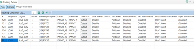
Step-2: Pin config in port driver

Step-3: Pwm driver configuration
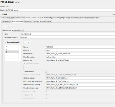
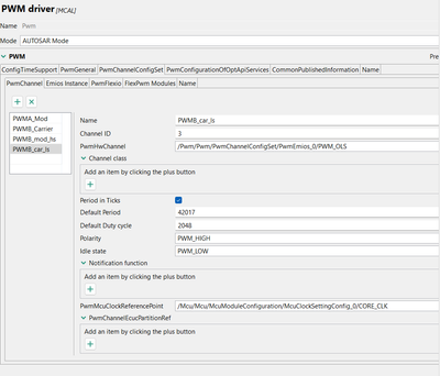
Step-4: Trigmux configuration for Ptc10 (Lcu1_out11)
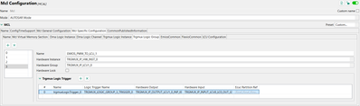
Step-5: Lcu_instance configuration
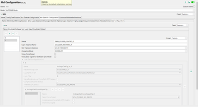
Step-6: Lcu logic input config

Step-7: Lcu logic output configuration
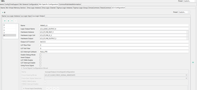
Kindly check this configuration, we think that we have made some small mistake in this.
We want to generate High side pwm pulse in "PTA0" - this is ok
and Low side PWM pulse in "PTC10" - this we tried but the waveform is not able to view without fast update method.
Kindly help us with this configuration.
Thanks & regards,
Vijay
stefanvlad
- Mark as New
- Bookmark
- Subscribe
- Mute
- Subscribe to RSS Feed
- Permalink
- Report Inappropriate Content
Hi @Vijay98 ,
Can you repost the images? since they are very low resolution and cannot be read properly.
Regarding the PTC10 output, I have already given the solution and required steps in this post Re: Pwm_delay_in_trigger_pulse - NXP Community
I am able to generate the PWM_Modulator frequency of 1000Hz (1kHz) using the Period = 7270 :

And for Period = 43500 i was able to get PWM_Modulator frequency to 167Hz:

But for even lower frequency you need to modify the PWM configuration for both PWM channels in order to keep that 11x times frequency in between them.
Best regards,
Stefan V.
- Mark as New
- Bookmark
- Subscribe
- Mute
- Subscribe to RSS Feed
- Permalink
- Report Inappropriate Content
Hello @stefanvlad
Thanks for the update and we have checked with that configuration.
1. With fast update method that you provided is that we have an issue in generating low side pulse in PTC10 pin. Kindly check the video uploaded with this post.

2. That we have a low side pulse already generated in PTA3 pin and we have to change that output to PTC10 pin (low side pulse).

For that we need help with configuration to generate the low side pulse in PTC10 pin.
Kindly help us with this,
Thanks & regards,
Vijay
stefanvlad
- Mark as New
- Bookmark
- Subscribe
- Mute
- Subscribe to RSS Feed
- Permalink
- Report Inappropriate Content
Hi @Vijay98 ,
I'm not sure what do you mean having an issue on PTC10, since on this thread Re: Pwm_delay_in_trigger_pulse - NXP Community, the solution works well and tested on logic analyzer.
Can you provide pictures of the model that you modified based on the steps i provided in the thread above, instead of reposting my screenshots.
Once again to use another pin to output the signal from PTA3 to PTC10 there are only two options, one is presented above by using PTC10 as emios_0_ch6 and the other solution is to use PTC10 as lcu1_out11:
Then you need to route the signal from PTA3 (lcu0_out2) to PTC10 (lcu1_out11) using TRGMUX:
Then we need to update the LCU configuration for the new input:
And then we update the LCU output config:
Also PTC10 pin needs to be added into the Port peripheral:
and the last step is to update the model with the new LCU output:
After this, clean up the local Matlab folder, delete the .slxc file, and the folders 32k312_pwm_lcu_mod_carrier_s32ct_ert_rtw, and slprj:
Then rebuild and flash the project on the S32K312 board, and check the pins with logic analyzer:
And to summarize the complete application, how all the peripherals are connected, I have created this diagram:
This are all the steps needed, please read them carefully and replicate them on your model,
Best regards,
Stefan V.
- Mark as New
- Bookmark
- Subscribe
- Mute
- Subscribe to RSS Feed
- Permalink
- Report Inappropriate Content
- Mark as New
- Bookmark
- Subscribe
- Mute
- Subscribe to RSS Feed
- Permalink
- Report Inappropriate Content
Hello nxp ,
Any update on this Lcu pin configuration
Kindly help us on this issue
Thanks & regards,
Vijay
- Mark as New
- Bookmark
- Subscribe
- Mute
- Subscribe to RSS Feed
- Permalink
- Report Inappropriate Content
Hello Nxp Team,
Currently we are working in Pwm pulse generation using Lcu & Trigmux with the help of Re: Pwm_delay_in_trigger_pulse - NXP Community this post.
We want to route the "PTA3" pin which pwm is already generated by Lcu configuration to "PTC10" pin by Lcu configuration.
But we are trying to configure the PTC10 pin (LCU1_out11) in LCU configuration and trying to generate pwm pulse. But we are unable to generate pulse in that pin. Here by, we are attached the file and steps that we are configured.
Step-1: Pin configuration for PTC-10 pin.

Step-2: Port configuration for Ptc10 pin.

Step-3: Pwm peripheral configuration for PTC-10


Step-4: Trigmux configuration for Ptc10 - LCU1_out11

Step-5: Lcu configuration- lcu logic instance config

Step-6: Lcu configuration - Lcu input

Step-7: Lcu configuration - Lcu output

Step-8: In model -> initialize system -> configured Mcl output state - 4

Kindly help to check this configuration for routing the Lcu output of 'PTA3' pwm to 'PTC10' pin with LCU configuration.
Kindly help us to resolve this issue.
Thanks & regards,
Vijay
@stefanvlad @dragostoma @Irina_Costachescu @Adrian_Gherca @DrKarthi @Kavin_raj_mbd
- Mark as New
- Bookmark
- Subscribe
- Mute
- Subscribe to RSS Feed
- Permalink
- Report Inappropriate Content
Hello @stefanvlad
We tried the model attached with this post and we can be able to Change the period and duty cycle with this model and able to see the waveform.
Thank you for your support for this method.
But we have a doubt that the modulator wave inside the carrier wave gets keep on updating (running) -> kindly see the video attached with this post.
It is ok for the modulator wave is running like that or can we stop that?
Thanks & regards
Vijay
stefanvlad
- Mark as New
- Bookmark
- Subscribe
- Mute
- Subscribe to RSS Feed
- Permalink
- Report Inappropriate Content
Hi @Vijay98
Glad to hear that this works better,
I saw the issue presented in the Video, maybe there is a problem with the Oscilloscope trigger?
In my case the duty cycle is changed only when i change it in FreeMASTER, otherwise it is kept constant, as in the picture below:

Can you check the same pins with a logic analyzer?
Stefan V.
- Mark as New
- Bookmark
- Subscribe
- Mute
- Subscribe to RSS Feed
- Permalink
- Report Inappropriate Content
Hello @stefanvlad
Thank you for your response
We have checked the waveform,
and right now we need to change only the LCU pins for our hardware for that,
1. In MCL component -> LCU configuration what are the configuration need to be changed? (for pin change)
For ex: I need to change the pin from PTA3 to PTA0 and i configured pins in pin configuration & in peripherals port has been configured and then in Lcu how to configure that pin?
2. which logic analyzer is used to measure the pwm signal from your side?
Thanks & regards,
Esakki.P
stefanvlad
- Mark as New
- Bookmark
- Subscribe
- Mute
- Subscribe to RSS Feed
- Permalink
- Report Inappropriate Content
Hi @Vijay98 ,
To change the LCU output pins it is not easy(feasible), since all the Inputs/Outputs are tightly related to the existing LCU0 pins:

Instead, we can use TrgMux to re-route the PTA3 output to PTA0, there are multiple steps required:
1. in the MCL Configuration , Trgmux Logic Instance, add input LCU0_LC0_OUT_I2:

2. LCU Configuration, add an Lcu Logic Input, set to LCU_IP_MUX_SEL_LU_IN_2:

3. LCU Logic Output, add another ouput to LC_1, set to LCU_IP_HW_OUTPUT_0 :

4. In the Simulink model, Initialize Function we need to add another MCL_LCU Output:

I have updated the model with PWM_FastUpdate functions, that can be used(applied) also in your original model that used Software Trigger, to improve the update time, in my model this takes around 7us to update 2 PWM channels:

Visualize the results with the logic analyzer(Saleae Logic 8 or others from ebay/Aliexp) using the Logic2 software:

Also i have update the FreeMASTER model, so now it can change both Duty cycles and same Period:

This is all from my side, you can find the updated model in the archive: s32k312_pwm_lcu_mod_carrier_s32ct.zip

Best regards,
Stefan V.
- Mark as New
- Bookmark
- Subscribe
- Mute
- Subscribe to RSS Feed
- Permalink
- Report Inappropriate Content
Hello @stefanvlad
Thanks for the update.
we have checked the model and its output pwm pulse in Saleae Logic 8 (logic analyzer)
we can be able to see the pulses and checked that the delay is reduced but we have an issue is that the pulse inside the Carrier (i.e., the modulator pulse in PTD2 & PTA0) is changing like keep on running.
I have attached the video of the pulses that we captured using logic analyzer and its logic analyzer file with this post.
we have tried giving different duty cycle and period for both the pulses, but we are facing that issue (modulator pulse is running).
Kindly help us to resolve this issue
Thanks & regards,
Vijay
stefanvlad
- Mark as New
- Bookmark
- Subscribe
- Mute
- Subscribe to RSS Feed
- Permalink
- Report Inappropriate Content
Hi @Vijay98 ,
This is normal , since the Logic Analyzer software is plotting the captured samples in a increasing time domain on the X axis.
The effect you are seeing in the video , i think it is due to aliasing in between the captured PWM frequency, the Logic software rendering and the display refresh rate.
The only issue i could find is regarding the PWM frequency:

But this is due to PWM generation based on the PLL jitter, there is information about this jitter in the S32K3xx Data Sheet:

Since the PLL clock is generating the CORE_CLK that goes into EMIOS_CLK that generates the PWM signals, according to this diagram:

Hope this answered your questions,
Best regards,
Stefan V.
