
- Forums
- Product Forums
- General Purpose MicrocontrollersGeneral Purpose Microcontrollers
- i.MX Forumsi.MX Forums
- QorIQ Processing PlatformsQorIQ Processing Platforms
- Identification and SecurityIdentification and Security
- Power ManagementPower Management
- Wireless ConnectivityWireless Connectivity
- RFID / NFCRFID / NFC
- Advanced AnalogAdvanced Analog
- MCX Microcontrollers
- S32G
- S32K
- S32V
- MPC5xxx
- Other NXP Products
- S12 / MagniV Microcontrollers
- Powertrain and Electrification Analog Drivers
- Sensors
- Vybrid Processors
- Digital Signal Controllers
- 8-bit Microcontrollers
- ColdFire/68K Microcontrollers and Processors
- PowerQUICC Processors
- OSBDM and TBDML
- S32M
- S32Z/E
-
- Solution Forums
- Software Forums
- MCUXpresso Software and ToolsMCUXpresso Software and Tools
- CodeWarriorCodeWarrior
- MQX Software SolutionsMQX Software Solutions
- Model-Based Design Toolbox (MBDT)Model-Based Design Toolbox (MBDT)
- FreeMASTER
- eIQ Machine Learning Software
- Embedded Software and Tools Clinic
- S32 SDK
- S32 Design Studio
- GUI Guider
- Zephyr Project
- Voice Technology
- Application Software Packs
- Secure Provisioning SDK (SPSDK)
- Processor Expert Software
- Generative AI & LLMs
-
- Topics
- Mobile Robotics - Drones and RoversMobile Robotics - Drones and Rovers
- NXP Training ContentNXP Training Content
- University ProgramsUniversity Programs
- Rapid IoT
- NXP Designs
- SafeAssure-Community
- OSS Security & Maintenance
- Using Our Community
-
- Cloud Lab Forums
-
- Knowledge Bases
- ARM Microcontrollers
- i.MX Processors
- Identification and Security
- Model-Based Design Toolbox (MBDT)
- QorIQ Processing Platforms
- S32 Automotive Processing Platform
- Wireless Connectivity
- CodeWarrior
- MCUXpresso Suite of Software and Tools
- MQX Software Solutions
- RFID / NFC
- Advanced Analog
-
- NXP Tech Blogs
- Home
- :
- MCUXpresso Software and Tools
- :
- MCUXpresso IDE
- :
- Re: How to just upload a binary file ?
How to just upload a binary file ?
- Subscribe to RSS Feed
- Mark Topic as New
- Mark Topic as Read
- Float this Topic for Current User
- Bookmark
- Subscribe
- Mute
- Printer Friendly Page
How to just upload a binary file ?
- Mark as New
- Bookmark
- Subscribe
- Mute
- Subscribe to RSS Feed
- Permalink
- Report Inappropriate Content
Hello,
I have the MCU-link device, and the software MCUXpresso IDE is installed on my PC.
My goal is to upload a binary file to a sample pcb with a KL25 IC.
But it looks the process to do that is more complex that just open the binary file and press "upload to IC". If i right understood, i have first to create a complete project. I tried that but no success.
Could you please tell me if there is a tutorial showing from zero how to create a complete project which allows at the end to be able to use the GUI Flash Tool for binary file uploading ?
If no existing tutorial, could you please point me to the first steps to do ?
Regards.
- Mark as New
- Bookmark
- Subscribe
- Mute
- Subscribe to RSS Feed
- Permalink
- Report Inappropriate Content
Hello Erich,
Well noted.
I reduced my cable length to less than 10cm.
Thank you also for the interesting link.
I will wait a next version of our firmware with the possibilily to perform a mass erase via an USB command from our PC software (in case of), and i will try again the BIN file with secured FLASH.
One of my two KL25 pcbs is not working, even with the short cable (the other one works) ; i suspect this KL25 pcb has a problem. So i will wait for some other KL25 pcbs. This will take some time. Then i will come back to post a new report.
Regards.
- Mark as New
- Bookmark
- Subscribe
- Mute
- Subscribe to RSS Feed
- Permalink
- Report Inappropriate Content
Hello Erich,
Thank you very much for your help.
Yes, my sample PCB is connected to the debug probe "MCU-link" with 3 wires (DIO, CLK and GND).
I do not have the FRDM-KL25Z.
I do not have the J-Link debug probe.
I am presently making tests with a sample PCB with a KL27Z256 IC, because i do not have the final KL25 based sample PCB yet, but i think the process to upload a binary file is similar.
So i have installed the SDK for the KL27Z256, and the wizard has generated a complete project for this IC.
The software sees the "MCU-link" device.
But when i try to make an action with the "GUI Flash Tool", i see a window "SWD Configuration" which says "0 available SWD Devices detected. Connect a device and try again."
Can i consider that things look ok in the "MCUXpresso IDE" & "MCU-link" side, so the problem is now between the debug probe "MCU-link" and my PCB sample ?
Regards.
- Mark as New
- Bookmark
- Subscribe
- Mute
- Subscribe to RSS Feed
- Permalink
- Report Inappropriate Content
>>I do not have the FRDM-KL25Z.
I asked this because initially you said that you want to program a KL25, but it looks this was a type as you reference the KL27Z.
So it looks you have everything in place, and MCU-Link is fine too.
>>So i have installed the SDK for the KL27Z256, and the wizard has generated a complete project for this IC.
Have you tried to debug that project created? I would try this first and then use the "GUI Flash Programmer".
>>Can i consider that things look ok in the "MCUXpresso IDE" & "MCU-link" side, so the problem is now between the debug probe "MCU-link" and my PCB sample ?
Yes. I suspect your problem is that the probe cannot communicate to the KL27Z: check your SWD wires and make sure your MCU is properly powered. I recommend that you connect the Reset line to the MCU-Link too (see the wiring based on the FRDM-KL27Z board).
I hope this helps,
Erich
- Mark as New
- Bookmark
- Subscribe
- Mute
- Subscribe to RSS Feed
- Permalink
- Report Inappropriate Content
Yes, i am making presently the tests with a KL27 based pcb. This is a home made pcb. It is running a customised firmware. When i plug it to the PC via USB, i see it in the PC USB devices list.
I just received my sample of KL25 pcb. I am not able to check if it is 100% ok, because i am not able to upload any firmware in it. So i prefered to start my tests with the KL27 based pcb, because i am sure this one works well.
The Debug process returns a similar error than the "GUI Flash Tool" error: "Unable to connect wire for probe index 1. Error: Wire Ack Fault - target connected?"
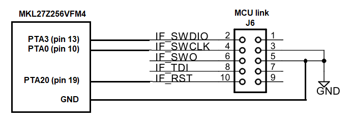
I added the "reset" wire, but no change.
Here is a schematic of the wires connections between the KL27 of my pcb sample and the MCU-link debug probe.
Could you please tell me if these connections are correct ?
- Mark as New
- Bookmark
- Subscribe
- Mute
- Subscribe to RSS Feed
- Permalink
- Report Inappropriate Content
Suggest you read this FAQ
https://community.nxp.com/t5/LPCXpresso-IDE-FAQs/Design-Considerations-for-Debug/m-p/469565
- Mark as New
- Bookmark
- Subscribe
- Mute
- Subscribe to RSS Feed
- Permalink
- Report Inappropriate Content
Thank you for this link.
I read the page. It looks like 3 wires are effectively needed (DIO, CLK, GND), plus RESET which is strongly recommended.
With my oscilloscope i see this in the debug port of the sample KL27 based PCB, when i press the button "Run" in the "GUI Flash Tool":
- there is some activity during around one second in the pins DIO and CLK
- then "MCUXpresso IDE" says "Unable to connect wire for probe index 1 ... Target connected?"
- then the pin RESET goes to low and stays at low until i disconnect/reconnect the MCU-link debug probe
I just tried with the KL25 based sample PCB (with KL25 SDK installed and project created from wizard), and same problem. It is written at the bottom right of the MCUXpresso window in red color: "No connection to chip's debug port".
It indeed looks like the connection between the MCU-link and the sample PCB is not correct.
I will re-check all connections.
- Mark as New
- Bookmark
- Subscribe
- Mute
- Subscribe to RSS Feed
- Permalink
- Report Inappropriate Content
Hello,
Sorry for the delay, but it took some time to make all tests.
I got 4 samples pcb's with the KL25 IC.
I sent 2 of them to Mark (mjbcswitzerland) for tests.
Mark has a P&E Multilink debug probe.
He had to add a connection to 3V3 [VCC] between the probe and the pcb, otherwise it wouldn't work.
Then he was able to program the pcb with his P&E from KDS, MCUXpresso and IAR.
So it seems this is not a hardware issue.
Then i added also the 3V3 [VCC] connection between my MCU-link probe and my sample pcb, and i tried again to control the KL25 of the sample pcb via MCUXpresso, but it is still not working.
Here is a screenshot of the error message.

- Mark as New
- Bookmark
- Subscribe
- Mute
- Subscribe to RSS Feed
- Permalink
- Report Inappropriate Content
Hi @offin ,
My goal is to upload a binary file to a sample pcb with a KL25 IC.
I assume that for your sample PCB you have a debug (JTAG/SWD) connector with the associated debug probe (LinkServer, P&E or SEGGER). If you are using the FRDM-KL25Z, then I assume you have programmed the board with the corresponding OpenSDA firmware.
Now it depends to some extend what binary (S19, Bin or Hex, see https://mcuoneclipse.com/2012/09/27/s-record-intel-hex-and-binary-files/ ) and debug connection you have. See https://mcuoneclipse.com/2017/05/06/using-eclipse-to-program-binary-files-to-an-embedded-target/.
For the 'GUI Flash Programmer' in the MCUXpresso IDE you have to have a project where it can store the settings. These come with the SDK files for the KL25Z (which I assume you have installed too).
Then it goes down to:
1) Create a new project using the Quickstart panel:

2) Start the 'Program to Flash' action as outlined in https://mcuoneclipse.com/2017/05/06/using-eclipse-to-program-binary-files-to-an-embedded-target/ and point to your binary.
3) done.
A much easier route is if you have a J-Link connection to the device.
Start the JFlashLite.exe (I assume Windows: it is in C:\Program Files (x86)\SEGGER\JLink) and specify your device:

Then specify your binary file and program it:

done.
I hope this helps,
Erich
- Mark as New
- Bookmark
- Subscribe
- Mute
- Subscribe to RSS Feed
- Permalink
- Report Inappropriate Content
Hello,
I just would like to give some news about our tests.
We got problems due to the length of the wiring from the MCU-link probe to our KL25 pcb. It was not working with our first wiring of 25 cm (10 inches). After reducing the length of the wiring to around 10 cm (4 inches), we are now able to upload a BIN file.
Then i tried to upload another BIN file with the option "secured" for the FLASH. The upload process was successful, but i had to repeat several times the process to perform a mass erase to free the FLASH again.
So we presently do not control 100% everything, but things are getting better.
We will try to understand why it does not work efficiently.
- Mark as New
- Bookmark
- Subscribe
- Mute
- Subscribe to RSS Feed
- Permalink
- Report Inappropriate Content
Hi @offin ,
25 cm SWD cable, wow!!!!! This is definitely too long. Think about the fact that this is is an unshielded cable, and everything beyond 10 cm is not really reasonable. If you have the cable close to noise sources, things won't work.
In general, you might have a look at https://mcuoneclipse.com/2014/11/03/debugging-failure-check-list-and-hints/ so it really could be about your design too.
As for the mass erase: make sure your reset circuit is rock solid too, and don't forget the need for a good power supply.
I hope this helps,
Erich
- Mark as New
- Bookmark
- Subscribe
- Mute
- Subscribe to RSS Feed
- Permalink
- Report Inappropriate Content
Hello,
During the past few days, i was making several tests with my self made pcb (i still have only one KL25 pcb). Everything was working well (dozens of uploads without any problem) until i uploaded by mistake a BIN file with secured FLASH
Then the problem happen again. I tried these options:
- Target operation > Program (mass erase first) with another BIN file (without secured FLASH)
- Target operation > masse erase
- above actions with the script "kinetismasserase.spc"
- Target Operation > Resurrect locked Kinetis device
But, no luck like the previous time, no success at all.
I see a first window "SWD Configuration" > "0 SWD Devices detected".
I press "Cancel".
And the log says:
...
Using memory from core 0 after searching for a good core
redlink server client - failed to receive response (to op 62) from server after 2000ms - timed out (rc 138)
...
May be i do not check the correct options to mass erase the FLASH (?) If yes, could you please tell me the required options ?
In case of i used already the correct options:
the SWD cable length for this pcb is 14cm (yes a bit more than 10cm). Do you think this can be always ok to upload BIN files, but not ok when the FLASH is secured ? So i should first shortened also this cable and try again ?
- Mark as New
- Bookmark
- Subscribe
- Mute
- Subscribe to RSS Feed
- Permalink
- Report Inappropriate Content
I made more tests.
I think it is better to open a new thread with it, because this problem is different than the first one.