- Forums
- Product Forums
- General Purpose MicrocontrollersGeneral Purpose Microcontrollers
- i.MX Forumsi.MX Forums
- QorIQ Processing PlatformsQorIQ Processing Platforms
- Identification and SecurityIdentification and Security
- Power ManagementPower Management
- Wireless ConnectivityWireless Connectivity
- RFID / NFCRFID / NFC
- MCX Microcontrollers
- S32G
- S32K
- S32V
- MPC5xxx
- Other NXP Products
- S12 / MagniV Microcontrollers
- Powertrain and Electrification Analog Drivers
- Sensors
- Vybrid Processors
- Digital Signal Controllers
- 8-bit Microcontrollers
- ColdFire/68K Microcontrollers and Processors
- PowerQUICC Processors
- OSBDM and TBDML
- S32M
-
- Solution Forums
- Software Forums
- MCUXpresso Software and ToolsMCUXpresso Software and Tools
- CodeWarriorCodeWarrior
- MQX Software SolutionsMQX Software Solutions
- Model-Based Design Toolbox (MBDT)Model-Based Design Toolbox (MBDT)
- FreeMASTER
- eIQ Machine Learning Software
- Embedded Software and Tools Clinic
- S32 SDK
- S32 Design Studio
- GUI Guider
- Zephyr Project
- Voice Technology
- Application Software Packs
- Secure Provisioning SDK (SPSDK)
- Processor Expert Software
-
- Topics
- Mobile Robotics - Drones and RoversMobile Robotics - Drones and Rovers
- NXP Training ContentNXP Training Content
- University ProgramsUniversity Programs
- Rapid IoT
- NXP Designs
- SafeAssure-Community
- OSS Security & Maintenance
- Using Our Community
-
- Cloud Lab Forums
-
- Knowledge Bases
- ARM Microcontrollers
- i.MX Processors
- Identification and Security
- Model-Based Design Toolbox (MBDT)
- QorIQ Processing Platforms
- S32 Automotive Processing Platform
- Wireless Connectivity
- CodeWarrior
- MCUXpresso Suite of Software and Tools
- MQX Software Solutions
- RFID / NFC
-
- Home
- :
- Product Forums
- :
- S32K
- :
- Question on Duty Ratio of S32k144
Question on Duty Ratio of S32k144
- Subscribe to RSS Feed
- Mark Topic as New
- Mark Topic as Read
- Float this Topic for Current User
- Bookmark
- Subscribe
- Mute
- Printer Friendly Page
- Mark as New
- Bookmark
- Subscribe
- Mute
- Subscribe to RSS Feed
- Permalink
- Report Inappropriate Content
I have completed a PWM code with a duty ratio of 1KHz and 0.5D.
And I adjusted the cnv value between 0 and 8000 because I wanted to adjust D.
But it worked contrary to what I thought.
From the FTM0 Initialization function: I wanted 0.1 duty for 800cnv based on 8,000tick.
However, the results showed a waveform of 0.9D.
Why does this result come out even though it's in low true mode?
How should I solve this in order to do it the way I want?
I am attaching my code at the bottom.
=======================================================================
#include "device_registers.h"
#include "clocks_and_modes.h"
int lpit0_ch0_flag_counter = 0; /*< LPIT0 timeout counter */
void LPIT0_init (uint32_t delay)
{
uint32_t timeout;
/*!
* LPIT Clocking:
* ==============================
*/
PCC->PCCn[PCC_LPIT_INDEX] = PCC_PCCn_PCS(6); /* Clock src=6 (SPLL2_DIV2_CLK)*/
PCC->PCCn[PCC_LPIT_INDEX] |= PCC_PCCn_CGC_MASK; /* Enable clk to LPIT0 regs */
/*!
* LPIT Initialization:
*/
LPIT0->MCR |= LPIT_MCR_M_CEN_MASK; /* DBG_EN-0: Timer chans stop in Debug mode */
/* DOZE_EN=0: Timer chans are stopped in DOZE mode */
/* SW_RST=0: SW reset does not reset timer chans, regs */
/* M_CEN=1: enable module clk (allows writing other LPIT0 regs) */
timeout=delay* 40;
LPIT0->TMR[0].TVAL = timeout; /* Chan 0 Timeout period: 40M clocks */
LPIT0->TMR[0].TCTRL |= LPIT_TMR_TCTRL_T_EN_MASK;
/* T_EN=1: Timer channel is enabled */
/* CHAIN=0: channel chaining is disabled */
/* MODE=0: 32 periodic counter mode */
/* TSOT=0: Timer decrements immediately based on restart */
/* TSOI=0: Timer does not stop after timeout */
/* TROT=0 Timer will not reload on trigger */
/* TRG_src=0: External trigger soruce */
/* TRG_SEL=0: Timer chan 0 trigger source is selected*/
}
void delay_us (volatile int us){
LPIT0_init(us); /* Initialize PIT0 for 1 second timeout */
while (0 == (LPIT0->MSR & LPIT_MSR_TIF0_MASK)) {} /* Wait for LPIT0 CH0 Flag */
lpit0_ch0_flag_counter++; /* Increment LPIT0 timeout counter */
LPIT0->MSR |= LPIT_MSR_TIF0_MASK; /* Clear LPIT0 timer flag 0 */
}
void FTM_init (void){
//FTM0 clocking
PCC->PCCn[PCC_FTM0_INDEX] &= ~PCC_PCCn_CGC_MASK; //Ensure clk diabled for config
PCC->PCCn[PCC_FTM0_INDEX] |= PCC_PCCn_PCS(0b010) //Clocksrc=1, 8MHz SIRCDIV1_CLK
| PCC_PCCn_CGC_MASK; //Enable clock for FTM regs
//FTM0 Initialization
FTM0->SC = FTM_SC_PWMEN1_MASK //Enable PWM channel 1output
|FTM_SC_PS(0); //TOIE(timer overflow Interrupt Ena) = 0 (deafault)
//CPWMS(Center aligned PWM Select) =0 (default, up count)
/* CLKS (Clock source) = 0 (default, no clock; FTM disabled) */
/* PS (Prescaler factor) = 0. Prescaler = 1 */
FTM0->MOD = 8000-1; //FTM0 counter final value (used for PWM mode)
// FTM0 Period = MOD-CNTIN+0x0001~=16000 ctr clks=8ms
//8Mhz /1 =8MHz -> ticks -> 1KHz
FTM0->CNTIN = FTM_CNTIN_INIT(0);
FTM0->CONTROLS[1].CnSC |=FTM_CnSC_MSB_MASK;
FTM0->CONTROLS[1].CnSC |=FTM_CnSC_ELSA_MASK; /* FTM0 ch1: edge-aligned PWM, low true pulses */
/* CHIE (Chan Interrupt Ena) = 0 (default) */
/* MSB:MSA (chan Mode Select)=0b10, Edge Align PWM */
/* ELSB:ELSA (chan Edge/Level Select)=0b10, low true */
}
void FTM0_CH1_PWM (){
FTM0->CONTROLS[1].CnV = 4000;//8000~0 duty; ex(7200=> Duty 0.1 / 800=>Duty 0.9)
//start FTM0 counter with clk source = external clock (SOSCDIV1_CLK)
FTM0->SC|=FTM_SC_CLKS(3);
}
void PORT_init (void)
{
/*!
* Pins definitions
* ===================================================
*
* Pin number | Function
* ----------------- |------------------
* PTD16 | FTM0CH1
*/
PCC->PCCn[PCC_PORTD_INDEX ]|=PCC_PCCn_CGC_MASK; /* Enable clock for PORTD */
PORTD->PCR[16]|=PORT_PCR_MUX(2); /* Port D16: MUX = ALT2, FTM0CH1 */
}
int main(void)
{
SOSC_init_8MHz(); /* Initialize system oscillator for 8 MHz xtal */
SPLL_init_160MHz(); /* Initialize SPLL to 160 MHz with 8 MHz SOSC */
NormalRUNmode_80MHz(); /* Init clocks: 80 MHz SPLL & core, 40 MHz bus, 20 MHz flash */
FTM_init();
FTM0_CH1_PWM ();
PORT_init(); /* Configure ports */
for(;;)
{
}
}
Solved! Go to Solution.
- Mark as New
- Bookmark
- Subscribe
- Mute
- Subscribe to RSS Feed
- Permalink
- Report Inappropriate Content
Hi @DKTempest,
You wrote:
From the FTM0 Initialization function: I wanted 0.1 duty for 800cnv based on 8,000tick.
However, the results showed a waveform of 0.9D.
FTM int function:
FTM0->CONTROLS[1].CnSC |=FTM_CnSC_MSB_MASK;
FTM0->CONTROLS[1].CnSC |=FTM_CnSC_ELSA_MASK; /* FTM0 ch1: edge-aligned PWM, low true pulses */
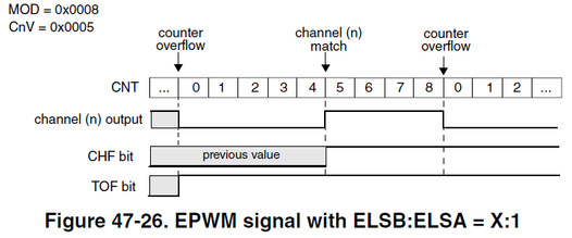
MSB = 1, ELSA = 1
If MOD = 8000-1 & CnV = 800, then the duty-cycle (HIGH level) is 90% from the match to overflow.
You can change it to MSB = 1, ELSB = 1, ELSA = 0 to get the expected result:
Regards,
Daniel
- Mark as New
- Bookmark
- Subscribe
- Mute
- Subscribe to RSS Feed
- Permalink
- Report Inappropriate Content
Thank you for your kind explanation.
I could understand it at once with your explanation.
However, there is an additional minor question.
In the process of setting ELSA = 0, I simply set it to 0x0.
Are there any other registers or masks that set this up?
FTM int function:
FTM0->CONTROLS[1].CnSC |=FTM_CnSC_MSB_MASK;
FTM0->CONTROLS[1].CnSC |=0x0;
FTM0->CONTROLS[1].CnSC |=FTM_CnSC_ELSB_MASK;
Thx 4 Daniel
- Mark as New
- Bookmark
- Subscribe
- Mute
- Subscribe to RSS Feed
- Permalink
- Report Inappropriate Content
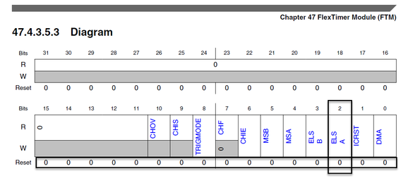
The ELSA bit reads 0 out of reset.
There is no need to mask the bit, just leave it as it is.
Regards,
Daniel
- Mark as New
- Bookmark
- Subscribe
- Mute
- Subscribe to RSS Feed
- Permalink
- Report Inappropriate Content
dear daniel
I think I found a typo in the datasheet.
In 1427page,
Shouldn't it be 'Low true' when MSB=1, ELSB=1, and ELSA=0?
These two explanations seem to have changed positions??
- Mark as New
- Bookmark
- Subscribe
- Mute
- Subscribe to RSS Feed
- Permalink
- Report Inappropriate Content
Hi @DKTempest,
I just tested it and the RM description is correct.
If MSB=1, ELSB=1 and ELSA=0, the PWM signal is HIGH at the beginning of the period and LOW after the match.
Regards,
Daniel
- Mark as New
- Bookmark
- Subscribe
- Mute
- Subscribe to RSS Feed
- Permalink
- Report Inappropriate Content
Thank you for your kind explanation.
- Mark as New
- Bookmark
- Subscribe
- Mute
- Subscribe to RSS Feed
- Permalink
- Report Inappropriate Content
FTM0->CONTROLS[1].CnSC |=FTM_CnSC_MSB_MASK;
FTM0->CONTROLS[1].CnSC |=FTM_CnSC_ELSB_MASK;
Then do I just need to remove 0x0 and mask ELSB?
- Mark as New
- Bookmark
- Subscribe
- Mute
- Subscribe to RSS Feed
- Permalink
- Report Inappropriate Content
Hi @DKTempest,
The "x" in the PWM mode description means "don't care".
So, it really does not matter.
Just set the bits that need to be set.
All the bits are cleared out of reset.
Regards,
Daniel
- Mark as New
- Bookmark
- Subscribe
- Mute
- Subscribe to RSS Feed
- Permalink
- Report Inappropriate Content
good for me
THX Daniel.


