
- Forums
- Product Forums
- General Purpose MicrocontrollersGeneral Purpose Microcontrollers
- i.MX Forumsi.MX Forums
- QorIQ Processing PlatformsQorIQ Processing Platforms
- Identification and SecurityIdentification and Security
- Power ManagementPower Management
- Wireless ConnectivityWireless Connectivity
- RFID / NFCRFID / NFC
- Advanced AnalogAdvanced Analog
- Neural Processing UnitsNeural Processing Units
- MCX Microcontrollers
- S32G
- S32K
- S32V
- MPC5xxx
- Other NXP Products
- S12 / MagniV Microcontrollers
- Powertrain and Electrification Analog Drivers
- Sensors
- Vybrid Processors
- Digital Signal Controllers
- 8-bit Microcontrollers
- ColdFire/68K Microcontrollers and Processors
- PowerQUICC Processors
- OSBDM and TBDML
- S32M
- S32Z/E
-
- Solution Forums
- Software Forums
- MCUXpresso Software and ToolsMCUXpresso Software and Tools
- CodeWarriorCodeWarrior
- MQX Software SolutionsMQX Software Solutions
- Model-Based Design Toolbox (MBDT)Model-Based Design Toolbox (MBDT)
- FreeMASTER
- eIQ Machine Learning Software
- Embedded Software and Tools Clinic
- S32 SDK
- S32 Design Studio
- GUI Guider
- Zephyr Project
- Voice Technology
- Application Software Packs
- Secure Provisioning SDK (SPSDK)
- Processor Expert Software
- Generative AI & LLMs
-
- Topics
- Mobile Robotics - Drones and RoversMobile Robotics - Drones and Rovers
- NXP Training ContentNXP Training Content
- University ProgramsUniversity Programs
- Rapid IoT
- NXP Designs
- SafeAssure-Community
- OSS Security & Maintenance
- Using Our Community
-
- Cloud Lab Forums
-
- Knowledge Bases
- ARM Microcontrollers
- i.MX Processors
- Identification and Security
- Model-Based Design Toolbox (MBDT)
- QorIQ Processing Platforms
- S32 Automotive Processing Platform
- Wireless Connectivity
- CodeWarrior
- MCUXpresso Suite of Software and Tools
- MQX Software Solutions
- RFID / NFC
- Advanced Analog
- Neural Processing Units
-
- NXP Tech Blogs
- Home
- :
- 製品フォーラム
- :
- S12 / MagniVマイクロコントローラ
- :
- Question about S12ZV safety manual
Question about S12ZV safety manual
- RSS フィードを購読する
- トピックを新着としてマーク
- トピックを既読としてマーク
- このトピックを現在のユーザーにフロートします
- ブックマーク
- 購読
- ミュート
- 印刷用ページ

 Vincent_Jung
- 新着としてマーク
- ブックマーク
- 購読
- ミュート
- RSS フィードを購読する
- ハイライト
- 印刷
- 不適切なコンテンツを報告
Hello Team,
in S12ZV safety manual, NXP recommended capacitor value that not exceed 680 for reset pin to gnd.
and there is also time constant RC=7.62us.
could someone explain why we gave these kind recommend and how to related it to safety.?


解決済! 解決策の投稿を見る。
 RadekS
- 新着としてマーク
- ブックマーク
- 購読
- ミュート
- RSS フィードを購読する
- ハイライト
- 印刷
- 不適切なコンテンツを報告
Hi Vincent,
The reason is a correct detection of reset source.
In the case of any reset, the reset circuit holds RESET pin low for 512 PLLCLK cycles.
The detection is realized at the time point after 256 PLLCLK cycles from RESET pin release.
If the voltage at RESET pin is low at that point, the External RESET pin is assumed as a reset source.
The PLLCLK (VCO frequency during system reset fVCORST) is typically 8~32MHz. So, in the worst case, the voltage at RESET pin should be detected as high after 256 cycles at 32MHz = 8us.
The minimum input high level is defined as 0.65*VDDX.
The RC time constant of reset circuit refers to the time where voltage should be 63.2% of VDDX.
So, we may approximately estimate maximum capacitance/minimum pull-up resistor from simple formula C<256/(R*fPLLCLK).
More details and higher accuracy calculation could be found in document:
https://community.nxp.com/docs/DOC-103737
There is one additional option: we can connect Schottky diode between MCU reset pin and external RC circuit (capacitor and pull-up). In the case of system reset (caused by MCU), an external capacitor isn’t discharged and COP/CM detection works correctly even with 100nF capacitor. See attached circuit.
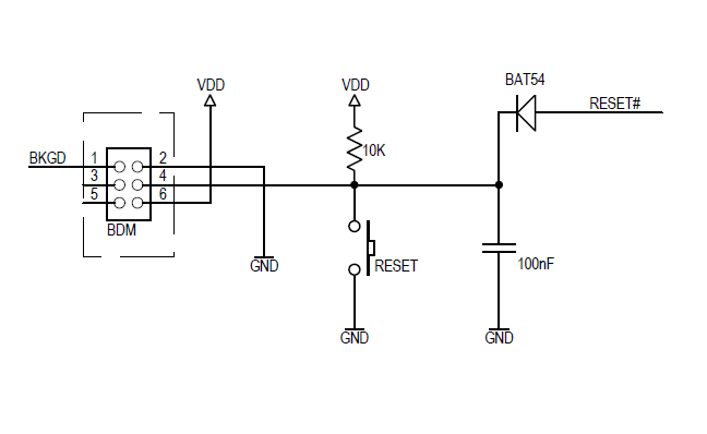
I hope it helps you.
Have a great day,
Radek
-----------------------------------------------------------------------------------------------------------------------
Note: If this post answers your question, please click the Correct Answer button. Thank you!
-----------------------------------------------------------------------------------------------------------------------
RadekS
- 新着としてマーク
- ブックマーク
- 購読
- ミュート
- RSS フィードを購読する
- ハイライト
- 印刷
- 不適切なコンテンツを報告
Hi Vincent,
The reason is a correct detection of reset source.
In the case of any reset, the reset circuit holds RESET pin low for 512 PLLCLK cycles.
The detection is realized at the time point after 256 PLLCLK cycles from RESET pin release.
If the voltage at RESET pin is low at that point, the External RESET pin is assumed as a reset source.
The PLLCLK (VCO frequency during system reset fVCORST) is typically 8~32MHz. So, in the worst case, the voltage at RESET pin should be detected as high after 256 cycles at 32MHz = 8us.
The minimum input high level is defined as 0.65*VDDX.
The RC time constant of reset circuit refers to the time where voltage should be 63.2% of VDDX.
So, we may approximately estimate maximum capacitance/minimum pull-up resistor from simple formula C<256/(R*fPLLCLK).
More details and higher accuracy calculation could be found in document:
https://community.nxp.com/docs/DOC-103737
There is one additional option: we can connect Schottky diode between MCU reset pin and external RC circuit (capacitor and pull-up). In the case of system reset (caused by MCU), an external capacitor isn’t discharged and COP/CM detection works correctly even with 100nF capacitor. See attached circuit.
I hope it helps you.
Have a great day,
Radek
-----------------------------------------------------------------------------------------------------------------------
Note: If this post answers your question, please click the Correct Answer button. Thank you!
-----------------------------------------------------------------------------------------------------------------------
Vincent_Jung
- 新着としてマーク
- ブックマーク
- 購読
- ミュート
- RSS フィードを購読する
- ハイライト
- 印刷
- 不適切なコンテンツを報告
Hi Racek.
Thanks for your kindly explanation.
