
- Forums
- Product Forums
- General Purpose MicrocontrollersGeneral Purpose Microcontrollers
- i.MX Forumsi.MX Forums
- QorIQ Processing PlatformsQorIQ Processing Platforms
- Identification and SecurityIdentification and Security
- Power ManagementPower Management
- Wireless ConnectivityWireless Connectivity
- RFID / NFCRFID / NFC
- Advanced AnalogAdvanced Analog
- Neural Processing UnitsNeural Processing Units
- MCX Microcontrollers
- S32G
- S32K
- S32V
- MPC5xxx
- Other NXP Products
- S12 / MagniV Microcontrollers
- Powertrain and Electrification Analog Drivers
- Sensors
- Vybrid Processors
- Digital Signal Controllers
- 8-bit Microcontrollers
- ColdFire/68K Microcontrollers and Processors
- PowerQUICC Processors
- OSBDM and TBDML
- S32M
- S32Z/E
-
- Solution Forums
- Software Forums
- MCUXpresso Software and ToolsMCUXpresso Software and Tools
- CodeWarriorCodeWarrior
- MQX Software SolutionsMQX Software Solutions
- Model-Based Design Toolbox (MBDT)Model-Based Design Toolbox (MBDT)
- FreeMASTER
- eIQ Machine Learning Software
- Embedded Software and Tools Clinic
- S32 SDK
- S32 Design Studio
- GUI Guider
- Zephyr Project
- Voice Technology
- Application Software Packs
- Secure Provisioning SDK (SPSDK)
- Processor Expert Software
- Generative AI & LLMs
-
- Topics
- Mobile Robotics - Drones and RoversMobile Robotics - Drones and Rovers
- NXP Training ContentNXP Training Content
- University ProgramsUniversity Programs
- Rapid IoT
- NXP Designs
- SafeAssure-Community
- OSS Security & Maintenance
- Using Our Community
-
- Cloud Lab Forums
-
- Knowledge Bases
- ARM Microcontrollers
- i.MX Processors
- Identification and Security
- Model-Based Design Toolbox (MBDT)
- QorIQ Processing Platforms
- S32 Automotive Processing Platform
- Wireless Connectivity
- CodeWarrior
- MCUXpresso Suite of Software and Tools
- MQX Software Solutions
- RFID / NFC
- Advanced Analog
- Neural Processing Units
-
- NXP Tech Blogs
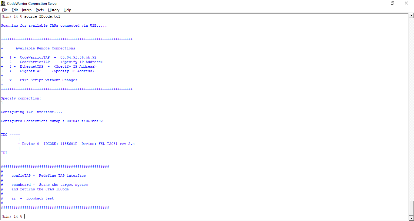
T2081 JTAG Testing
Dear All,
We have designed customize T2081 based SBC. Now we want to check whether the JTAG in our board is working or not using code warrior?
Can you please provide step by step guidelines or any document to check the working of our custom board JTAG using code warrior?
Regards
Hemant
Hi,
Thanks for the response. Now, we are able to fetch the information using JTAG Referring your article.
Attaching the image for the reference.
But now, when we try to upload the code for basic but getting the error "Failed to correctly configure the jtag chain". Attaching the log for the you reference.
Please help to resolve the issue.
Regards
Hemant
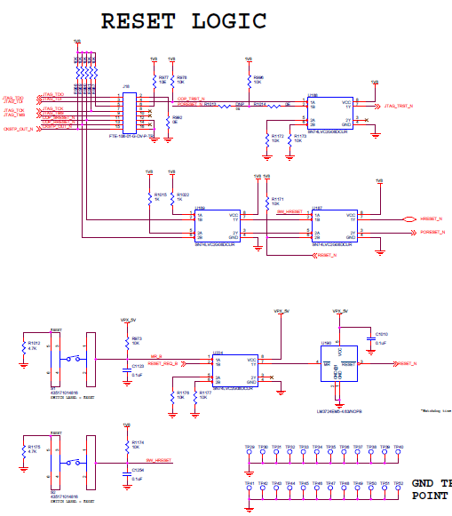
1) HRESET_B must not be driven by an external source.
---> It is Driven by 1.8V present in the system
2) Which cfg_rcw_src is selected?
--->We have selected Hard-code RCW i.e. 010011011
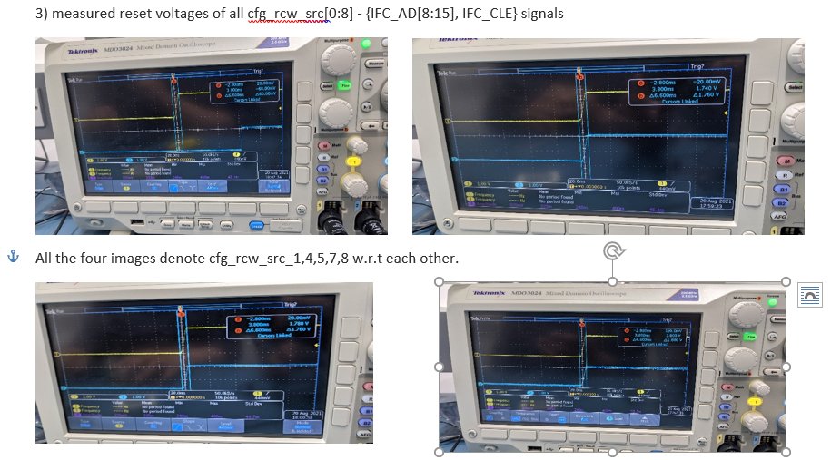
What are POR voltages on {IFC_AD[8:15], IFC_CLE}?
--->All the IFC_AD[8:15], IFC_CLE are connected to 1.8V.
Attaching the reset circuit for review.
HRESET_B must be driven by open-drain gate - refer to the AN4804 - QorIQ T2080 Design Checklist, Figure 3. JTAG interface connection, note 7.
It is not clear how to interpret provided traces because they do not contain PORESET_B signal.
1) Is the schematics page 8 accurate and the cfg_rcw_src really is strapped to 0_10011011?
The 0_10011011 is not documented in the QorIQ T2080 Reference Manual, Table 4-15. Hard-Coded RCW Options.
2) Which SerDes reference clocks are applied?
Refer to the QorIQ T2080 Reference Manual, Table 4-16. RCW Settings for Hard-Coded RCW Options:
SRDS_PLL_REF_CLK_SEL_S1
SRDS_PLL_REF_CLK_SEL_S2
1) Is the schematics page 8 accurate and the cfg_rcw_src really is strapped to 0_10011011?
The 0_10011011 is not documented in the QorIQ T2080 Reference Manual, Table 4-15. Hard-Coded RCW Options.
--> We have referred QorIQ T2080 Reference Design Board Quick Start. Refer page page-9

2) Which SerDes reference clocks are applied?
--> Is it a software setting or we have to do in our custom board. Regarding clock circuit we have used sysclk as 66.66Mhz and DDR CLK as 133.33Mhz.
Also, without doing hardcode and make NOR Flash as a primary boot can we flash the basic SRAM code as we have fixed sysclock as 66.66Mhz and DDR CLK as 133.33Mhz as recommended in the T2080 reference design.

Required modifications:
1) disconnect U187[7] from the processor
2) RESET_REQ_B connection is incorrect.
RESET_REQ_B must be connected so, that if it is asserted, then resulting PORESET_B assertion duration must be not less than 1 ms. Consider that RESET_REQ_B is deasserted within several SYSCLKs after PORESET_B assertion is detected.
During bring-up it is recommended to disconnect U223[2] from processor's RESET_REQ_B and pull-up resistor.
3) supported hard-coded RCW options, SYSCLK and DDRCLK frequencies are provided in the QorIQ T2080 Reference Manual, Table 4-15. Hard-Coded RCW Options.
thankyou for the inputs. I have made the changes according your suggestion.
Just need to confirm below points:

In the above image I am getting two option for Hard-coded RCW (0x8C) or (0x8F). Which one I have to select for my T2081 custom board?
In T2080RM, I have selected below hardcore option 0_100110x (where x is denoted by 0). Here the frequency of both sysclk and ddrclk is 66.66Mhz where in the tool (refer above image) frequency are different. Can you clear the confusion? What frequency I have to select for proper testing?

If PBL TOOL IS OUT OF DATE, THEN AFTER DOING THE MODIFICATIONS HOW I AM GOING TO FLASH MY CUSTOM BOARD WITH HARDCORE RCW?
1)Please find the attached schematic after the modification suggested by you. Please verify the same.
2)Now as per my understanding in order to boot we are just using POREST as we disconnected HRESET and reset_req. Please correct me if I am wrong.
Because as per T2080RM Figure 4-1. Power-on reset sequence we require all the sequence which we have omitted from the design. Please clarify the doubt
3)If this was a case, then how I am able to boot using code warrior and able to access SRAM of T2081? If any steps are there, kindly share with us.
> we require all the sequence which we have omitted from the design
What exactly do you mean?
Consider that HRESET_B is driven by the processor during POR sequence.
> how I am able to boot using code warrior and able to access SRAM of T2081?
Please use CodeWarrior Flash Programmer and program valid RCW corresponding to your application into the boot Flash.
Consider that cfg_rcw_src strapping must be adjusted accordingly to the selected boot Flash.
Consider that HRESET_B is driven by the processor during POR sequence.
--> it means the modification which I made in the attached schematic suggested by you are correct. Please verify the same.
Please use CodeWarrior Flash Programmer and program valid RCW corresponding to your application into the boot Flash.
Consider that cfg_rcw_src strapping must be adjusted accordingly to the selected boot Flash.
-->With hardcoding RCW option, What is the procedure to flash internal SRAM of T2081? (Note we are not using NOR and NAND for primary flash).