
- Forums
- Product Forums
- General Purpose MicrocontrollersGeneral Purpose Microcontrollers
- i.MX Forumsi.MX Forums
- QorIQ Processing PlatformsQorIQ Processing Platforms
- Identification and SecurityIdentification and Security
- Power ManagementPower Management
- Wireless ConnectivityWireless Connectivity
- RFID / NFCRFID / NFC
- Advanced AnalogAdvanced Analog
- Neural Processing UnitsNeural Processing Units
- MCX Microcontrollers
- S32G
- S32K
- S32V
- MPC5xxx
- Other NXP Products
- S12 / MagniV Microcontrollers
- Powertrain and Electrification Analog Drivers
- Sensors
- Vybrid Processors
- Digital Signal Controllers
- 8-bit Microcontrollers
- ColdFire/68K Microcontrollers and Processors
- PowerQUICC Processors
- OSBDM and TBDML
- S32M
- S32Z/E
-
- Solution Forums
- Software Forums
- MCUXpresso Software and ToolsMCUXpresso Software and Tools
- CodeWarriorCodeWarrior
- MQX Software SolutionsMQX Software Solutions
- Model-Based Design Toolbox (MBDT)Model-Based Design Toolbox (MBDT)
- FreeMASTER
- eIQ Machine Learning Software
- Embedded Software and Tools Clinic
- S32 SDK
- S32 Design Studio
- GUI Guider
- Zephyr Project
- Voice Technology
- Application Software Packs
- Secure Provisioning SDK (SPSDK)
- Processor Expert Software
- Generative AI & LLMs
-
- Topics
- Mobile Robotics - Drones and RoversMobile Robotics - Drones and Rovers
- NXP Training ContentNXP Training Content
- University ProgramsUniversity Programs
- Rapid IoT
- NXP Designs
- SafeAssure-Community
- OSS Security & Maintenance
- Using Our Community
-
- Cloud Lab Forums
-
- Knowledge Bases
- ARM Microcontrollers
- i.MX Processors
- Identification and Security
- Model-Based Design Toolbox (MBDT)
- QorIQ Processing Platforms
- S32 Automotive Processing Platform
- Wireless Connectivity
- CodeWarrior
- MCUXpresso Suite of Software and Tools
- MQX Software Solutions
- RFID / NFC
- Advanced Analog
- Neural Processing Units
-
- NXP Tech Blogs
- Home
- :
- Translated Content
- :
- Multi Source Translation Content
- :
- 1116501_en-US
1116501_en-US
- RSS フィードを購読する
- 新着としてマーク
- 既読としてマーク
- ブックマーク
- 購読
- 印刷用ページ
- 不適切なコンテンツを報告
1116501_en-US
1116501_en-US
For iMX6DQ, there are two IPUs, so they can support up to 4 cameras at the same time. But the default BSP can only support up to two cameras at the same time.

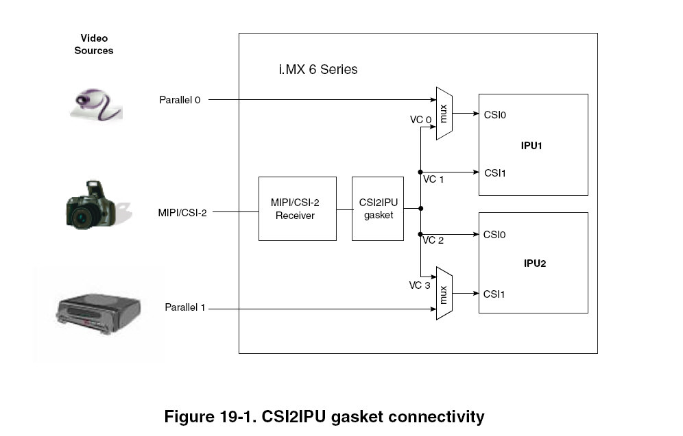
The attached patch can make the BSP support up to 4 cameras based on 3.10.53 GA 1.1.0 BSP.
The 4 cameras can be:
- 1xCSI, 3xMIPI
- 2xCSI, 2xMIPI
- 4xMIPI
For 4xMIPI case, the four cameras should be combined on the single MIPI CSI2 interface, and each camera data should be transfered on a mipi virtual channel.
In this patch, we given the example driver for Maxim MAX9286, it was verified working on iMX6DQ SabreAuto board. The input to MAX9286 is four 720P30 cameras.
The verified camera boards:
(1) Onsemi AR0140+AP0101+MAX9271 boards.
(2) OmniVision OV10635+MAX9271 boards.
The MIPI CSI2 CVBS camera surround view solution can be found at: iMX6DQ ISL79985/79987 MIPI CSI2 CVBS camera surround view solution for Linux BSP
The MIPI CSI2 CVBS HD camera surround view solution can be found at: iMX6DQ TP2854 MIPI CSI2 720P CVBS camera surround view solution for Linux BSP
The kernel patches:
0001-IPU-update-IPU-capture-driver-to-support-up-to-four-.patch
Updated IPU common code to support up to four cameras.
0002-Add-Max9286-support-on-SabreAuto-board-which-can-sup.patch
MAX9286 driver, it includes MAX9271, AP0101 and AR0140 drivers.
0003-Remove-the-page-size-align-requirement-for-v4l2-capt.patch
With this patch, the mxc_v4l2_tvin test application can use overlay framebuffer as V4l2 capture buffer directly.
0004-Max9286-skip-AP0101-camera-re-initialization.patch
If the camera board's power had been kept after initialized, this patch will bypass the re-initialization to reduce the start up time.
0005-Max9286-set-I2C-speed-to-400Kbps.patch
Set I2C to 400Kbps to reduce the AP0101+AR0140 initialization time.
0006-Max9286-add-retry-for-MAX9271-I2C-access.patch
Added retry for MAX9271 I2C access.
0007-Max9286-Add-support-for-OV10635-camera.patch
Updated code for OV10635 camera.
0008-Max9286-support-auto-detect-camera-number.patch
Make the Max9286 driver can detect the camera number automatically.
How to builld the kernel with MAX9286 support:
make imx_v7_defconfig
make menuconfig (In this command, you should select the MAX9286 driver:
Device Drivers --->
<*> Multimedia support --->
[*] V4L platform devices --->
<*> MXC Video For Linux Video Capture
MXC Camera/V4L2 PRP Features support --->
<*>Maxim max9286 GMSL Deserializer Input support
Select Camera Sensor (OmniVision OV10635 camera sensor) // Or (Onsemi AP0101 and AR0140 camera sensor)
<*>mxc VADC support
<*>Select Overlay Rounting (Queue ipu device for overlay library)
<*>Pre-processor Encoder library
<*>IPU CSI Encoder library)
make zImage
make dtbs
The built out image file:
arch/arm/boot/dts/imx6q-sabreauto.dtb
arch/arm/boot/zImage
"mxc_v4l2_tvin_max9286.tar.gz" is the test application, test command to capture the four cameras and render on 1080P HDMI display:
/mxc_v4l2_tvin.out -ol 0 -ot 0 -ow 960 -oh 540 -d 1 -x 0 -g2d &
/mxc_v4l2_tvin.out -ol 960 -ot 0 -ow 960 -oh 540 -d 1 -x 1 -g2d &
/mxc_v4l2_tvin.out -ol 0 -ot 540 -ow 960 -oh 540 -d 1 -x 2 -g2d &
/mxc_v4l2_tvin.out -ol 960 -ot 540 -ow 960 -oh 540 -d 1 -x 3 -g2d &
Some hardware check point on AR0140+AP0101+MAX9271 camera board (Please get MAX9286 and OV10635 schematics from Maxim):
1. In this patch, MAX9286's I2C address is 0x4D, so ADD0 and ADD1 should be connected to high.
AP0101's I2C address is 0xBA, so SADDR should be connected to high.
2. AP0101's DOUT0~DOUT7 should be connected to MAX9271's DIN7~DIN0, the order should be switched, MSB connected to LSB.
3. MAX9271's GPO pin should be connected to AP0101's FRAME_SYNC pin. The pull down resistance on FRAME_SYNC pin should not be 0 ohm.
Some known limitation:
1. AP0101's VSYNC invalid time, last video line's HSYNC to VSYNC porch's max value is 255 pixel clocks, it is not enough for MAX9286 to generate the Frame End MIPI packets for each camera. So in order to let iMX6DQ to capture 1280x720 video for each camera, we had let AP0101 output 1280*724 frame size, and iMX6 will only capture 720 lines, the remained video data and Frame End will be ignored.
This solution will not impact the function, but there will be "Error matching Frame Start with Frame End for Virtual Channel x" error reported from iMX6 MIPI_CSI_ERR1 register.
Maxim suggested to use MAX96705 to relace the MAX9271, it can delay the VSYNC invalid time, then the MIPI error will be fixed.
2015-11-17 update: Updated for OV10635 camera support.
File: L3.10.53_GA1.1.0_MAX9286_Surroundview_Patch_2015-11-17.zip
2015-12-04 update:
File: L3.10.53_GA1.1.0_MAX9286_Surroundview_Patch_2015-12-04.zip
Added patch 0009-Max9286-updated-PCLK-edge-setting-for-OV10635.patch to correct the OV10635 PCLK edge setting
2016-03-07 update:
File L3.14.38_GA_MAX9286_Surroundview_Patch_2016-03-07.zip
Added kernel patch for L3.14.38 GA 1.1.0 BSP.
2016-07-26 update:
Files: L3.10.53_GA1.1.0_MAX9286_Surroundview_Patch_2016-07-26.zip; L3.14.38_GA1.1.0_MAX9286_Surroundview_Patch_2016-07-26.zip; L3.14.52_GA1.1.0_MAX9286_Surroundview_Patch_2016-07-26.zip.
Added gstreamer support.
Added MAX96705 support.
Added patch for L3.14.52_GA1.1.0.
2017-12-11 update:
Added CVBS surround view link: iMX6DQ TP2854 MIPI CSI2 720P CVBS camera surround view solution for Linux BSP
2021-04-26 update:
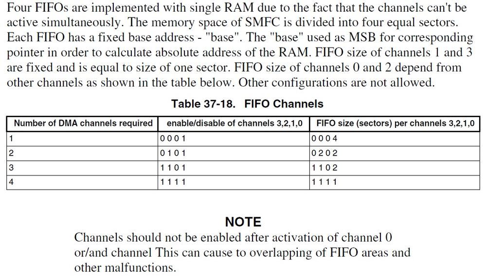
Some customer reported, when system loading is heavy, sometimes, some camera will flicker left and right. It is caused by SFMC FIFO data lost. The original patch used IDMAC 0 and IDMAC 1 for two cameras on one IPU, this is not the best setting.
IDMAC 1 is fixed to use 1/4 SMFC FIFO and it will cause IDMAC 0 to use 1/4 SMFC FIFO too. And another 1/2 of SMFC FIFO can't be used in this case.
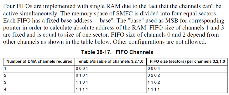
Some code update to improve it:
For each IPU, please use IDMAC 0 and IDMAC 2 to capture the two cameras.
This needs change the hard coding in "drivers\media\platform\mxc\capture\ipu_csi_enc.c",
"CSI_MEM1" and "IPU_IRQ_CSI1_OUT_EOF" should be changed to "CSI_MEM2" and "IPU_IRQ_CSI2_OUT_EOF". In this case, all SMFC FIFO can be used.
And in "ipu_common.c", function ipu_probe(), the followed code should be changed to make IDMAC2 use high priority too.
/* Set sync refresh channels and CSI->mem channel as high priority */
- ipu_idmac_write(ipu, 0x18800003L, IDMAC_CHA_PRI(0));
+ ipu_idmac_write(ipu, 0x1880000FL, IDMAC_CHA_PRI(0));
As I explained, this is the render issue, for 60fps display, the PAN display can only be up to 60fps, but for 4x720P30 camera, if you render them alone, there are total 120fps, so it can't work correctly. You need combine the 4 cameras together then render them once.
The log shows there is no enough memory, I think you need reserve more memory for GPU.
Hi Qiang Li,
The following two pipelines work normally when run seperately.
- gst-launch-1.0 -v -e imxv4l2videosrc device=/dev/video0 ! imxg2dvideosink framebuffer=/dev/fb0 force-aspect-ratio=false
- gst-launch-1.0 -v -e imxv4l2videosrc device=/dev/video1 ! imxg2dvideosink framebuffer=/dev/fb0 force-aspect-ratio=false
However, each pipelines given below (especially with video3) cause sawtooth issue given as attached gif, even if they run seperately.
- gst-launch-1.0 -v -e imxv4l2videosrc device=/dev/video2 ! imxg2dvideosink framebuffer=/dev/fb0 force-aspect-ratio=false
- gst-launch-1.0 -v -e imxv4l2videosrc device=/dev/video3 ! imxg2dvideosink framebuffer=/dev/fb0 force-aspect-ratio=false

While twin app does not create any problem for each camera.
While using gstreamer, what can cause this situation? Is it about gstreamer patch or IPU2?
For gstreamer, when you render 4 cameras together, it needs combine the buffer 4 times and swap the buffer 4 times, this will impact the performance. For tvin test application, it just renders the cameras to target framebuffer directly, no buffer swap, this can cause sawtooth issue.
The best way for rendering: draw the 4 cameras to one target buffer, then swap it to frambuffer in one time.
Hi Qiang Li,
I am using Imx6qp. With following commands, the system is working properly.
WIDTH=640
HEIGHT=240
./mxc_v4l2_tvin.out -ol 0 -ot 0 -ow ${WIDTH} -oh ${HEIGHT} -d 0 -x 0 -g2d &
./mxc_v4l2_tvin.out -ol ${WIDTH} -ot 0 -ow ${WIDTH} -oh ${HEIGHT} -d 0 -x 1 -g2d &
./mxc_v4l2_tvin.out -ol 0 -ot ${HEIGHT} -ow ${WIDTH} -oh ${HEIGHT} -d 0 -x 2 -g2d &
./mxc_v4l2_tvin.out -ol ${WIDTH} -ot ${HEIGHT} -ow ${WIDTH} -oh ${HEIGHT} -d 0 -x 3 -g2d &
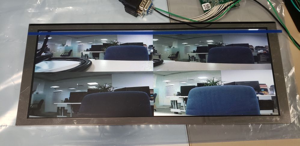
When I try to use gstreamer with the following pipelines, third and forth cameras are jittering and scrolling.
WINDOW1="window-x-coord=0 window-y-coord=0 window-width=${WIDTH} window-height=${HEIGHT}"
WINDOW2="window-x-coord=${WIDTH} window-y-coord=0 window-width=${WIDTH} window-height=${HEIGHT}"
WINDOW3="window-x-coord=0 window-y-coord=${HEIGHT} window-width=${WIDTH} window-height=${HEIGHT}"
WINDOW4="window-x-coord=${WIDTH} window-y-coord=${HEIGHT} window-width=${WIDTH} window-height=${HEIGHT}"
gst-launch-1.0 -v -e imxv4l2videosrc device=/dev/video0 ! imxg2dvideosink framebuffer=/dev/fb0 force-aspect-ratio=false $WINDOW1 &
gst-launch-1.0 -v -e imxv4l2videosrc device=/dev/video1 ! imxg2dvideosink framebuffer=/dev/fb0 force-aspect-ratio=false $WINDOW2 &
gst-launch-1.0 -v -e imxv4l2videosrc device=/dev/video2 ! imxg2dvideosink framebuffer=/dev/fb0 force-aspect-ratio=false $WINDOW3 &
gst-launch-1.0 -v -e imxv4l2videosrc device=/dev/video3 ! imxg2dvideosink framebuffer=/dev/fb0 force-aspect-ratio=false $WINDOW4 &
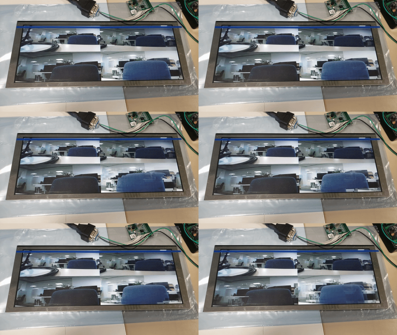
v4l applications are working properly but gstreamer causes the problem seen above. Do you have any idea about this problem?
Excuse me, can I have another patch of Linux 3.14.38? That link failed
Thanks a lot! Qiang Li.
Understand now.
2 x MIPI CSI2 means two MIPI virtual channels(VC1 and VC2) on one physical MIPI CSI2 interface.
Thanks Qiang!
So can we have 2 x BT656 and 2 x MIPI CSI2 work together? if yes , how many virtual channels(1~4) can each of the 2x MIPI CSI2 have?
Each IPU has two CSI modules, their input can be parallel CSI interface or MIPI CSI2 virtual channel. And for iMX6DQ, it can support up to two parallel CSI interfaces (BT656 interface). Both of them can work at the same time.
Dear Qiang Li,
Sorry, I am some confused, as you said, Imx6Q can support up to 4 cameras,
The 4 cameras can be:
- 1xCSI, 3xMIPI
- 2xCSI, 2xMIPI
- 4xMIPI
what is the meaning of 1x CSI and 3x MIPI, etc? usually we say MIPI CSI-2 together, CSI is the same thing as MIPI CSI-2?
BTW, how many BT656 interfaces can be directly supported by Imx6Q simultaneously?
Many thanks~~
Hi z dq,
Did you solve the instability problem? I got sensor clk error when connecting more than 2 cameras although MAX96705's GPO pin are connected to AP0101's FRAME_SYNC pin.
I rarely got the error with 2 cameras .
28.463487] max9286_mipi 1-006a: ap0101_initialize: AP0101 hasn't been found, reg = 0x0, index = 4.
[ 28.472625] max9286_mipi 1-006a: max9286_write_reg:write reg error:reg=34,val=b6
[ 28.673495] max9286_mipi 1-006a: max9271_write_reg:write reg error:reg= 4,val=83
[ 28.783553] max9286_mipi 1-006a: max9286_write_reg:write reg error:reg=15,val=9b
[ 29.403469] mipi csi2 can not receive sensor clk! MIPI_CSI_PHY_STATE = 0x6f0.
Regards
Hi, Liqiang
Could you please tell me what's the fps value
if we run the surroundview(4 camera 1280x720) application base your patch and Imx6d processor?
whether he DDR bandwidth is enough? thank you!
以下中文:
-----------------
如果使用这个patch并跑在imx6d的板子上,目前surroundview(基于4个720p的摄像头)能达到多少个fps,
内存带宽够用吗?谢谢!
---------------
The color issue happens between MAX96705 and MAX9286 mapping, so PC USB has no use for reference.
There are several kind of mapping order on data line, 8 bits/10bits, MSB/LSB. You need fine tuning it based on the OV10635 and MAX96705 connecting.
This had been explained, g2d_blit target buffer should be the current displayed framebuffer:
"
The current mxc_v4l2_tvin demo application will render camera video to current frame buffer directly, so there will be tearing issue.
For real use case, you need use multi-buffers, for example, the virtual framebuffer size is 3 times of real display buffer, and each time only one buffer is showing on display, so when buffer 1 is showing on display, you can draw combined camera videos into buffer 2, after finished drawing, call ioctl FBIOPAN_DISPLAY to show buffer 2 on screen.
"
Hi,liqiang
I have solve the color fault problem, by swap data line using ov10635 register 0x4709, so thank you very much!!
Hi, liqiang
In my local environment which using immunity mode, and do data line swap according to your suggestion,
which causes image color change but problem NOT solved.
(帖子里好像帖不了附件,单独像您提了一个问题。)
By the way, I am using leopardimaging LI-USB30-OV10635-SER camera as following:
https://www.leopardimaging.com/uploads/LI-OV10635-SER_datasheet.pdf
It works well when connecting to PC by USB 3.0.
please help check, thanks!
Hi Qiang Li:
The specific implementation is like this:
Get the real-time video data of the 4-way camera, display it on the GPU and display it in real time on the lvds screen. At the same time, the 4 channels of video are called by g2d to call the g2g_blit function for resize. The image of each frame is 720P resize to 640*480, and then synthesized into one frame. Image so that 4 channels of video can be displayed in one frame.the spliced video is not display on the screen and saved directly into the video,but now it is found that the video displayed by the GPU rendering in real time will be torn. Playback of the saved video also found that the image has a tearing problem, affecting the viewing effect.
But as long as these two functions are combined into one project, the problem of image tearing will occur when displaying and the saving video.
2. Is there a problem with data conflicts in the GPU? I have already made the GC2000 and GC320 get data that cannot be bufed, but after the two functions are integrated, there will still be a problem of video tearing.
Hi Qiang Li:
The specific implementation is like this:
Get the real-time video data of the 4-way camera, display it on the GPU and display it in real time on the lvds screen. At the same time, the 4 channels of video are called by g2d to call the g2g_blit function for resize. The image of each frame is 720P resize to 640*480, and then synthesized into one frame. Image so that 4 channels of video can be displayed in one frame.the spliced video is not display on the screen and saved directly into the video,but now it is found that the video displayed by the GPU rendering in real time will be torn. Playback of the saved video also found that the image has a tearing problem, affecting the viewing effect.
But as long as these two functions are combined into one project, the problem of image tearing will occur when displaying and the saving video.
2. Is there a problem with data conflicts in the GPU? I have already made the GC2000 and GC320 get data that cannot be bufed, but after the two functions are integrated, there will still be a problem of video tearing.
Hi Qiang Li,
Sorry, maybe I didn't tell you my question clearly:
1.When I don't use -g2d,the display image is ok,no screen tearing. And the demo code really use FBIOPAN_DISPLAY to change display buffer ;
2.But when I use -g2d,screen tearing occurs. And the demo code use g2d_blit to display. So my question is how to resolve this problem?
Thanks!
MAX96705 data line swap related code are in regiter 0x20~0x29; 0x30~0x39, you can find the discussion from old items here.
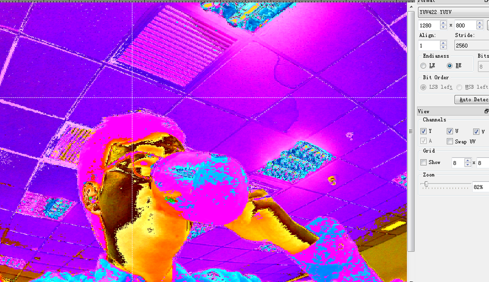
谢谢回复!
>The ov10635 and max9286 driver captured frame format is YUYV, that means data in buffer is YUYV, if your application handles it other format, such as RGB565, you can >get such wrong color issue
上面图片是使用7yuv查看的结果,选择的格式是YUYV;图像颜色不对。所以不是显示格式不匹配的问题。
>Another thing should be paied attention to is that the MAX96705 can swap the data line order, if you set it to wrong, the color is wrong.
请问您知道驱动那里可以swap dataline order吗?谢谢!
The ov10635 and max9286 driver captured frame format is YUYV, that means data in buffer is YUYV, if your application handles it other format, such as RGB565, you can get such wrong color issue.
Another thing should be paied attention to is that the MAX96705 can swap the data line order, if you set it to wrong, the color is wrong.
The current mxc_v4l2_tvin demo application will render camera video to current frame buffer directly, so there will be tearing issue.
For real use case, you need use multi-buffers, for example, the virtual framebuffer size is 3 times of real display buffer, and each time only one buffer is showing on display, so when buffer 1 is showing on display, you can draw combined camera videos into buffer 2, after finished drawing, call ioctl FBIOPAN_DISPLAY to show buffer 2 on screen.
Hi,Liqiang
We are developing 4 camera surroundview application, based on imx6d/OV10635/MAX96705/MAX9286 boards,
the patch we apply is L3.14.52_GA1.1.0_MAX9286_Surroundview_Patch_2016-07-26.zip.
but the image color is NOT right as following:
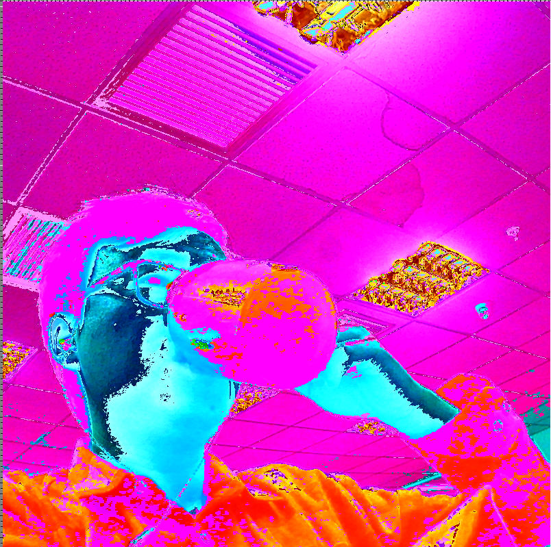
Can you please help ?
Thans for your support!
1. You means that if input resolution and format is same as output,IPU will not deal with it. Right?
2. I still have another question,when I use command with -g2d argument,like this:
root@imx6qsabresd:/# ./mxc_v4l2_tvin.out -ol 0 -ot 0 -ow 1280 -oh 720 -d 1 -x 0 -g2d,screen tearing occurs like the following picture:
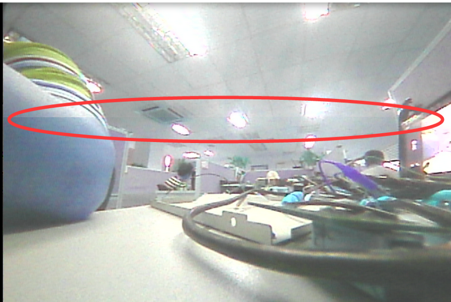
Could you give me some advice?Thanks!
The default IPU task doesn't support memory copy use case, input resolution and format is same as output.
Hi Qiang Li,
I meet following problem:when I use command without -g2d argument,it display following error,
root@imx6qsabresd:/# ./mxc_v4l2_tvin.out -ol 0 -ot 0 -ow 1280 -oh 720 -d 1 -x 0
g_in_width = 1280, g_in_height = 720.
fb_fix.id = DISP3 FG.
fb: smem_start = 0x26700000, smem_len = 0xa8c000.
fb: frame buffer size = 0x1c2000 bytes.
fb: g_screen_info.xres = 1280, g_screen_info.yres = 720.
fb: g_display_left = 0.
fb: g_display_top = 0.
fb: g_display_width = 1280.
fb: g_display_height = 720.
IPU_CHECK_TASK failed.
But when I use the command ./mxc_v4l2_tvin.out -ol 0 -ot 0 -ow 1280 -oh 719 -d 1 -x 0,the display image is OK.
what's the impossible reason?Thanks!
Hi,
How to build the "Surround View Application" and its required packages in Yocto for i.MX6 QuadPLUS
Hoping for a better guidance.
Regards,
Bala
Hi,Qiang Li,谢谢回复,我们现在确实是镜头模组上挂了个flash,不过flash里面的固件是安森美的代理商提供的,他们确认已经工作在framesync模式,并且这个固件已经有别的客户在量产,我们读出AP0101的0xC88C,0xC88D,0xC88E寄存器,值分别是0x03,0x03,0x00,同时通过逻辑分析仪分析AP0101对AR0143的配置,感觉也应该是正确的;max9286这端已经确认生成的framesync信号有传输到AP0101,现在sensor出来的帧率是25fps;
请问针对25fps,max9286这边的配置应该如果修改,盼复,谢谢!
The FLASH ROM setting on camera module should follow the driver's setting.
Hi,
VIDIOC_DQBUF error dissappears when I changed the test hardware with a new set. I will work on the real reason but it seems to be a hardware issue. Although I sometimes get VIDIOC_DQBUF and MIPI CLK errors; I can succesfully get the image with the below configuration.
- AR0140 sensor
- AP0101 ISP
- MAX96705 Serializer
- MAX9286 Deserializer
- Our designed daughter board between MAX9286 EVM and iMX6 board.
We use kernel 4.1.15 and use below switch code:
+ max9271_write_reg(i, 0x20, 0x07);
+ max9271_write_reg(i, 0x21, 0x06);
+ max9271_write_reg(i, 0x22, 0x05);
+ max9271_write_reg(i, 0x23, 0x04);
+ max9271_write_reg(i, 0x24, 0x03);
+ max9271_write_reg(i, 0x25, 0x02);
+ max9271_write_reg(i, 0x26, 0x01);
+ max9271_write_reg(i, 0x27, 0x00);
+
+
+ max9271_write_reg(i, 0x30, 0x17);
+ max9271_write_reg(i, 0x31, 0x16);
+ max9271_write_reg(i, 0x32, 0x15);
+ max9271_write_reg(i, 0x33, 0x14);
+ max9271_write_reg(i, 0x34, 0x13);
+ max9271_write_reg(i, 0x35, 0x12);
+ max9271_write_reg(i, 0x36, 0x11);
+ max9271_write_reg(i, 0x37, 0x10);
Thanks and best regards
Hi Ferhat,
The camera I used doesn't need such switch, so no such code in patch, but I had show you the sample code, for detail setting on MAX96705 switch, you can check with Maxim.
Hi Qiang Li,
Could not find the switch code on patch files. Could you please update the links with your latest versions?
Thanks and best regards
Hi DONGON KIM,
Some video combining chip can insert some bytes into each video line, then software can check these inserted data to identify the camera number.
The "0003-Add-Max9286-support-on-SabreAuto-board-which-can-sup.patch" files of the L3.14.38_GA andL3.14.52_GA patches have errors.
+static int max9271_write_reg(int index, u8 reg, u8 val)
+{
+ s32 ret;
+ int retry, timeout = 10;
+
+ max9286_data[0].i2c_client->addr = ADDR_MAX9271 + index;
+ for (retry = 0; retry < timeout; retry ++) {
+ ret = i2c_smbus_write_byte_data(max9286_data[0].i2c_client, reg, val);
+ if (val < 0)
+ msleep(5);
+ else
+ break;
+ }
+
+ if (retry >= timeout) {
+ dev_info(&max9286_data[0].i2c_client->dev,
+ "%s:write reg error:reg=%2x,val=%2x\n", __func__,
+ reg, val);
+ return -1;
+ }
+
+ return 0;
+}
Thanks for your ans.
Then, is there any example code for split the video from each virtual channel?
If not, may I know how to read the raw packet data of mipi_csi?
Thanks.
Hi Ferhat,
Yes, the switch code:
max9271_write_reg(0, 0x20, 0x09);
max9271_write_reg(0, 0x21, 0x08);
max9271_write_reg(0, 0x22, 0x07);
max9271_write_reg(0, 0x23, 0x06);
max9271_write_reg(0, 0x24, 0x05);
max9271_write_reg(0, 0x25, 0x04);
max9271_write_reg(0, 0x26, 0x03);
max9271_write_reg(0, 0x27, 0x02);
max9271_write_reg(0, 0x28, 0x01);
max9271_write_reg(0, 0x29, 0x00);
max9271_write_reg(0, 0x30, 0x19);
max9271_write_reg(0, 0x31, 0x18);
max9271_write_reg(0, 0x32, 0x17);
max9271_write_reg(0, 0x33, 0x16);
max9271_write_reg(0, 0x34, 0x15);
max9271_write_reg(0, 0x35, 0x14);
max9271_write_reg(0, 0x36, 0x13);
max9271_write_reg(0, 0x37, 0x12);
max9271_write_reg(0, 0x38, 0x11);
max9271_write_reg(0, 0x39, 0x10);
Hi Qiang,
Does the patch you provided include such swap settings on MAX96705? We use MAX96705 and do not do such swap by driver
Thank you
Hi Ferhat,
MAX9286's data mapping needs such MSB to LSB switch, if you are using MAX96705, it can do such swap by setting, but MAX9271 doesn't support it. And AP0101 doesn't dupport such swap too, so hardware should be modified.
Hi Dongoh,
The iMX8MQ can receive video with multiple virtual channels, but there is no hardware module to split the video from each virtual channel.
That means you need use software to split, and the MIPI sender need insert some flag to identify the data for each virtual channel.
Hi, Qiang Li
May I know the reason for i.MX8MQ can't support multiple virtual channel?
According to the features and functional description of MIPI-CSI2 Controller on Reference Manual for i.MX8M Quad,
i.MX8M seems to support multiple virtual channel.(13.6.1.1 and 13.6.3)
Thanks.
Dear Qiang Li,
I would like to know the reason of your hardware point stated as below.
"2) AP0101's DOUT0~DOUT7 should be connected to MAX9271's DIN7~DIN0, the order should be switched, MSB connected to LSB"
In our reference camera board supplied by Onsemi (MARS module) these pins are connected directly (DOUT0-DOUT7 to DIN0-DIN7). Is there any way to switch these connection by software? I could not find on datasheets of MAX96705 and AP0101.
Thanks
That means your patch porting has error, please check it.
Dear Qiang Li, we removed eeprom on the camera module and we switched it to host configuration mode by setting SPI-SDI pin to LOW. Thus it is initialized successfully by the driver of max9286 in the beginning, after kernel is loaded. Do you have any other suggestion for both "not a csi channel" and vidioc_dqbuf errors?
Thank you,
Best regards
“ap0101_initialize:AP0101 is already in Slave (Shutter-Sync) Mode”
This log means your camera had already be initialized, so you need check if there is flash ROM on your camera module which will initialize it during power on, if so, you need update that flash ROM to use the driver's setting.
Hi again Qiang Li,
As you can see in our logs, our camera is in shutter-sync mode, thus doesn't this means our camera setting is correct? What do you mean by camera setting, can you be more specific and explain it in detail?. Also MIPI_CSI_ERR1 register is 0, there is no error of transmission of bits, clock signal etc and mpi csi2 can receive the data correctly. Doesnot that mean that camera sends correct signals and is configured properly?
Secondly, we reviewed all patches and applied them directly by copy-paste, also we double checked whether there is an error; thus, we are (almost) sure that we ported correctly. What is the key points we need to look at? Can there be any other possible cause of this problem?
Thank you,
Best regards
For error "not a csi channel error", I think you haven't ported the patch successfully.
For error "vidioc_dqbuf failed", that means no available video frames had been captured. Maybe you need check your AP0101 camera setting.
Hi Qiang Li,
In our project we have one camera connected to max9286 and we applied your patches to 4.1.15 kernel; however when we test it, we get the following picture:
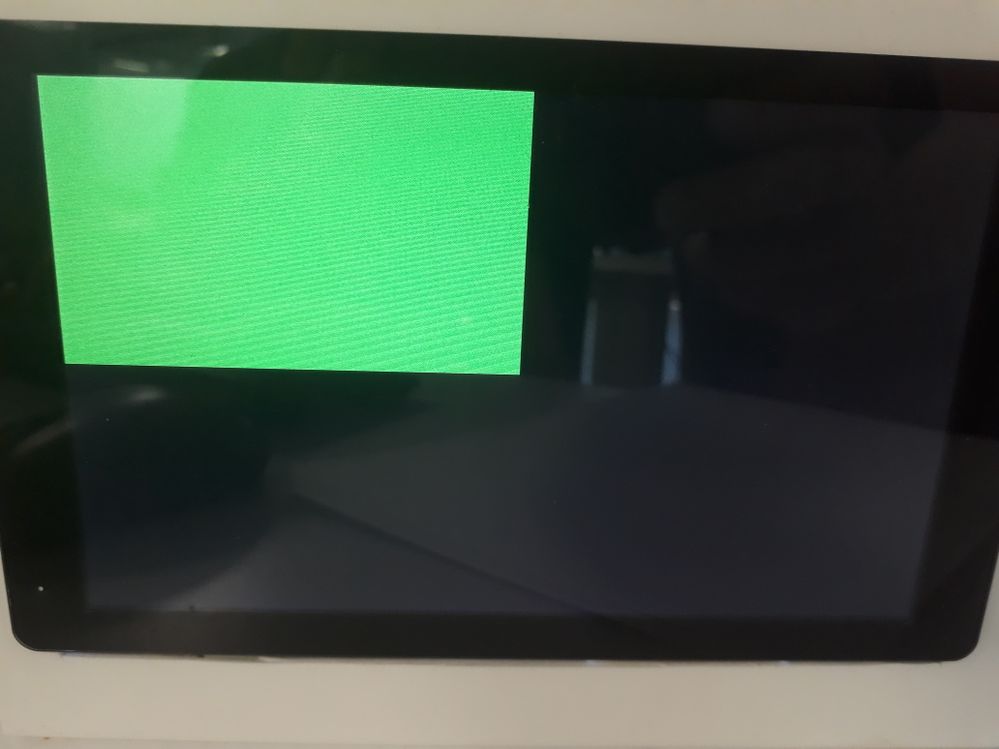
Logs are as follow:
root@esomimx6q:~# ./mxc_v4l2_tvin.out -ol 0 -ot 0 -ow 400 -oh 240 -d 1 -x 0
[ 3144.243857] max9286_mipi: sensor number = 1.
[ 3144.248939] mxc_mipi_csi2 21dc000.mipi_csi: mipi_csi2_reset: mipi_lane_bps = 148 Mbps
[ 3144.257446] mxc_mipi_csi2 21dc000.mipi_csi: mipi_csi2_reset: value = 0x42.
[ 3144.743416] max9286_mipi 1-006a: ap0101_initialize: AP0101 was found, index = 1.
[ 3144.751541] max9286_mipi 1-006a: ap0101_initialize:AP0101 is already in Slave (Shutter-Sync) Mode.
g_in_width = 1280, g_in_height = 720.
fb_fix.id = DISP4 FG.
fb: smem_start = 0x6a100000, smem_len = 0x8ca00.
fb: frame buffer size = 0x2ee00 bytes.
fb: g_screen_info.xres = 400, g_screen_info.yres = 240.
fb: g_display_left = 0.
fb: g_display_top = 0.
fb: g_display_width = 400.
fb: g_display_height = 240.
start time = 1535715437 s, 436911 us
[ 3154.993386] ERROR: v4l2 capture: mxc_v4l_dqueue timeout enc_counter 0
VIDIOC_DQBUF failed.
We could not understand the reason of the problem (also we adjusted gpr1 pins 19 and 20 as 0).
Secondly, the following logs show us that there are problems with /dev/video 1 and dev/video3 about csi channel although dev/video0 and /dev/video2 is ok , however all of them have timeout error (note that since only one camera is connected, only "cat /dev/video0" command can initialize ap0101).
root@esomimx6q:~# cat /dev/video0
[ 3313.913877] max9286_mipi: sensor number = 1.
[ 3313.918963] mxc_mipi_csi2 21dc000.mipi_csi: mipi_csi2_reset: mipi_lane_bps = 148 Mbps
[ 3313.926941] mxc_mipi_csi2 21dc000.mipi_csi: mipi_csi2_reset: value = 0x42.
[ 3314.413402] max9286_mipi 1-006a: ap0101_initialize: AP0101 was found, index = 1.
[ 3314.421469] max9286_mipi 1-006a: ap0101_initialize:AP0101 is already in Slave (Shutter-Sync) Mode.
[ 3324.583392] ERROR: v4l2 capture: mxc_v4l_read timeout counter 0
cat: read error: Timer expired
root@esomimx6q:~# cat /dev/video1
[ 3337.083393] ERROR: v4l2 capture: mxc_v4l_read timeout counter 0
[ 3337.089359] imx-ipuv3 2400000.ipu: Not a CSI channel
cat: read error: Timer expired
root@esomimx6q:~# cat /dev/video2
[ 3351.493394] ERROR: v4l2 capture: mxc_v4l_read timeout counter 0
cat: read error: Timer expired
root@esomimx6q:~# cat /dev/video3
[ 3403.463393] ERROR: v4l2 capture: mxc_v4l_read timeout counter 0
[ 3403.469360] imx-ipuv3 2800000.ipu: Not a CSI channel
cat: read error: Timer expired
Can you help us with them? What is the reason of "not a csi channel error" on video1 and video3 while others don't give this error. Also the first error is more important, which is the error of "vidioc_dqbuf failed".
Thank you
Best regards
You can check with the AP0101 camera chip vendor.
Hi Qiang Li,
My problem is as bellow.Can you help me to deal with it.
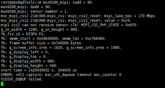
Thinks for your help!
I have other problem with devicetree.Look at the picture,reg=6A,but max9286 datasheet is no this address.
The head file is in your rootfs which is built from Yocto.
You can also use the binary "mxc_v4l2_tvin.out" directly.
Hi Qiang Li,
The test application file not contain "g2d.h",but "mxc_v4l2_tvin.c" has the code #include "g2d.h".So,when I make it,it turn out error.
Can you help me solve the problem?
Think you!
HI Qiang Li
When I use the "Patch",my kernel show error.My kernel vision is kernel-3.10.53.
So,I want to now what's the differance between the kernel-3.10.53 and L3.10.53_1.1.0-GA.
I think that the different vision make the error.
From real test, the total delay is about 86ms.
Camera number will not impact the delay, capture delay is fixed on camera fps, for example, 30fps camera input, the capture delay is 33ms. And render delay is fixed on display fps, for examlpe, 60Hz display, the delay is 17ms, then the post-process delay, it needs less than camera fps (33ms) to avoid frame lost. So for 8 camera case, you need make sure all the post process is less than 33ms to avoid frame drop.
Hi Li Qiang
Thank you for your Patch.
Now,I have some trouble when I use "patch".
Can you write a manual to me so that I can understand how to use the "patch".
Thanks Sincerely.
Zhongmao Liu.
Hi. Qiang Li
The four camera`s video can render on 1080P HDMI display.
How does the surround view algorithm get the four cameras`s capture buffers.
do you have some good ideas?
Hi Qiang Li !
Is it possible for you to share "60-persistent-v4l.rules" file? It should be inside /lib/udev/rules.d
Thank you very much
Regards,
Gokcen
Hi!
Thank you for the reply. The resolution is 1280x720. So, I think that is not the problem. We are using kernel version 4.1.15.
May the following errors be related to that?
[ 36.921793] v4l2_int_device wlcore_sdio mxc_dcic
[ 36.926813] CPU: 3 PID: 399 Comm: v4l_id Not tainted 4.1.15 #1
[ 94.823493] udevd[215]: worker [230] /devices/soc0/v4l2_cap_1/video4linux/video1 is taking a long time
[ 95.098316] udevd[230]: slow: 'v4l_id /dev/video1' [402]
bootlogd: cannot allocate pseudo tty: No such file or directory
Have a nice day!
As I remembered, the blank from frame end to new frame is not enough for AP0101, so even the camera output resolution is 1280*800, we need capture just 1280*720, otherwise, the video capture will fail.
Hi Qiang Lee,
I have tried initializing MAX9286 in high immunity mode and now, ar140 is being found. However, I think there is something wrong with the v4l part. Here is the related log :
[ 34.085201]
[ 34.086911] Internal error: Oops: 17 [#1] PREEMPT SMP ARM
[ 34.092313] Modules linked in: wlcore mxc_v4l2_capture ipu_bg_overlay_sdc ipu_still ipu_prp_enc ipu_csi_enc max9286_gmsl ipu_fg_overlay_sdc v4l2_int_device wlcore_sdio mxc_dcic
[ 34.108239] CPU: 3 PID: 402 Comm: v4l_id Not tainted 4.1.15 #1
[ 34.114078] Hardware name: Freescale i.MX6 Quad/DualLite (Device Tree)
[ 34.120628] task: d87b2ac0 ti: d8c78000 task.ti: d8c78000
[ 34.123891] max9286_mipi 1-006a: max9286_write_reg:write reg error:reg=3b,val=1e
[ 34.133488] PC is at mxc_v4l_do_ioctl+0xc4c/0x2590 [mxc_v4l2_capture]
[ 34.139979] LR is at mxc_v4l_do_ioctl+0xc3c/0x2590 [mxc_v4l2_capture]
[ 34.146476] pc : [<7f08539c>] lr : [<7f08538c>] psr: 600e0013
[ 34.146476] sp : d8c79e40 ip : 00000074 fp : 00000000
[ 34.157991] r10: d88f9300 r9 : 7f034094 r8 : d8c79e90
[ 34.163245] r7 : 80685600 r6 : 00000000 r5 : d8d19008 r4 : d8d19000
[ 34.169792] r3 : 00000000 r2 : d8c79ea7 r1 : 7f087ae0 r0 : d8c79ec0
[ 34.176346] Flags: nZCv IRQs on FIQs on Mode SVC_32 ISA ARM Segment user
[ 34.183504] Control: 10c53c7d Table: 6939c04a DAC: 00000015
[ 34.189288] Process v4l_id (pid: 402, stack limit = 0xd8c78210)
[ 34.195251] Stack: (0xd8c79e40 to 0xd8c7a000)
[ 34.199652] 9e40: d88f9300 00000000 00000000 00000000 d8868550 d6023000 d80fe028 d8c41700
[ 34.207872] 9e60: 80b154c0 80685600 00000068 00000000 00000002 7ebeec88 d8c79e90 7f084750
[ 34.216090] 9e80: 00000000 804dbc10 d88f9300 800f6978 5f63786d 326c3476 00000000 00000000
[ 34.224327] 9ea0: 3978616d 00363832 00000000 00000000 00000000 00000000 00000000 00000000
[ 34.232540] 9ec0: 00000000 00000000 00000000 00000000 00000000 00000000 00000000 00000000
[ 34.240757] 9ee0: 0004010f 85200005 05200005 00000000 00000000 00000000 9087e695 00000006
[ 34.248978] 9f00: d925f015 76f11000 00000000 d61505d8 d8ffa318 7ebeec88 d8ffa318 d88f9300
[ 34.253976] max9286_mipi: sensor number = 1.
[ 34.254788] mxc_mipi_csi2 21dc000.mipi_csi: mipi_csi2_reset: mipi_lane_bps = 148 Mbps
[ 34.254801] mxc_mipi_csi2 21dc000.mipi_csi: mipi_csi2_reset: value = 0x42.
[ 34.276213] 9f20: 00000003 7ebeec88 d8c78000 00000000 00000000 800fa0e4 d8c79f40 800e3970
[ 34.284441] 9f40: 80b06720 00000003 d88f9300 d925f000 d8ffa318 d88f9308 00000020 00000000
[ 34.292668] 9f60: 00000000 800e91ac 00000000 00000000 d88f9300 00000003 d88f9300 80685600
[ 34.300888] 9f80: 7ebeec88 d8c78000 00000000 800fa338 00000000 7ebeee54 00000003 00000036
[ 34.309102] 9fa0: 8000f604 8000f480 00000000 7ebeee54 00000003 80685600 7ebeec88 00000001
[ 34.317312] 9fc0: 00000000 7ebeee54 00000003 00000036 00000000 00000000 76f11000 00000000
[ 34.325534] 9fe0: 76e6e2a0 7ebeec7c 00011cfc 76e6e2ac 600e0010 00000003 8112f040 0420f044
[ 34.333788] [<7f08539c>] (mxc_v4l_do_ioctl [mxc_v4l2_capture]) from [<804dbc10>] (video_usercopy+0x1b8/0x480)
[ 34.343777] [<804dbc10>] (video_usercopy) from [<800fa0e4>] (do_vfs_ioctl+0x3e8/0x608)
[ 34.351752] [<800fa0e4>] (do_vfs_ioctl) from [<800fa338>] (SyS_ioctl+0x34/0x5c)
[ 34.359115] [<800fa338>] (SyS_ioctl) from [<8000f480>] (ret_fast_syscall+0x0/0x3c)
[ 34.366711] Code: e5993008 e3071ae0 e2880030 e3471f08 (e5932018)
[ 34.374557] ---[ end trace 756e286723ff907f ]---
[ 34.435645] FAT-fs (mmcblk1p1): Volume was not properly unmounted. Some data may be corrupt. Please run fsck.
[ 34.531108] kjournald starting. Commit interval 5 seconds
[ 34.549007] EXT4-fs (mmcblk1p2): recovery complete
[ 34.553859] EXT4-fs (mmcblk1p2): mounted filesystem with ordered data mode. Opts: (null)
[ 34.591916] EXT3-fs (mmcblk0p2): using internal journal
[ 34.597183] EXT3-fs (mmcblk0p2): recovery complete
[ 34.601980] EXT3-fs (mmcblk0p2): mounted filesystem with ordered data mode
[ 34.602407] FAT-fs (mmcblk0p1): Volume was not properly unmounted. Some data may be corrupt. Please run fsck.
[ 34.644868] wlcore: loaded
[ 34.733493] max9286_mipi 1-006a: ap0101_initialize: AP0101 was found, index = 1.
[ 35.357742] ap0101_LastPatchStatus
[ 35.812239] ap0101_LastPatchStatus
[ 35.985973] ap0101_LastPatchStatus
[ 36.194854] ap0101_LastPatchStatus
[ 36.243936] ap0101_LastPatchStatus
[ 36.392576] ap0101_LastPatchStatus
[ 37.086270] max9286_mipi 1-006a: ap0101_InitSensor: AR0140 was found, index = 1.
[ 94.823493] udevd[215]: worker [230] /devices/soc0/v4l2_cap_1/video4linux/video1 is taking a long time
[ 95.098316] udevd[230]: slow: 'v4l_id /dev/video1' [402]
bootlogd: cannot allocate pseudo tty: No such file or directory
Hi Qiang Li,
We have tried with the following equipment :
ONSEMI MARS Reference Desşgn (MAX96705, AP0101, AR0140)
30 cm RG174 (and also 3 m coaxial cable) included in the reference design.
MAX9286S32V Daugter board is used to connect iMX6 board.
I have taken AP0101 to host configuration mode by removing flash.
Despite I am writing 0x36 to MAX9286' s 34th register to disable local auto acknowledge, I observed that 9th bit coming immediately after 8th bit of SCL. I am attaching the oscilloscope view. The problematic bits are circled with red.
MAX9286 LFLT led is ON and LOCK led is OFF.
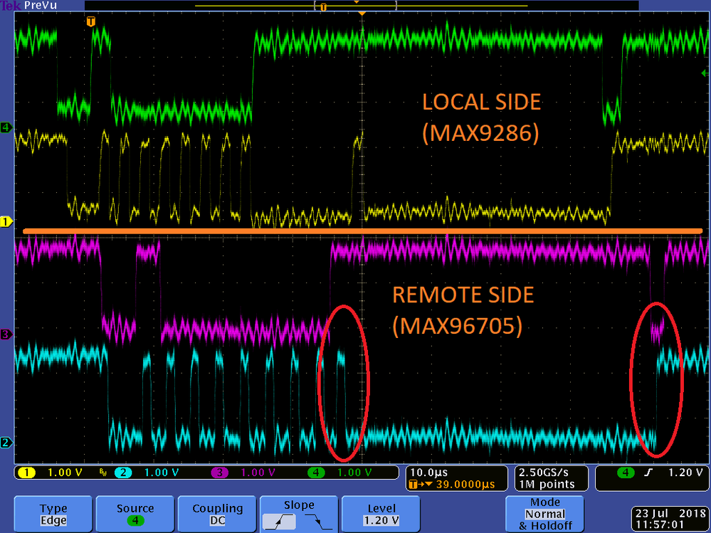
Down below, we tried to read from AP0101 (address: 0x92).

If you have any suggestions it would be appreciated.
Regards
Hi qiang,
The 4 cameras can be:
- 1xCSI, 3xMIPI
- 2xCSI, 2xMIPI
- 4xMIPI
可以解释一下上面的CSI和MIPI什么意思吗?不知道这个csi是指ipu内部的csi0-3 还是camera mipi总线。
Hi Qiang Li,
1xCSI, 3xMIPI, what does it meanning?
I think you need check the signal quality on Coax between MAX9286 and MAX96705.
Hi Qiang Lee!
I am using ap0101 with max96705 and max9286 deserializer. I was able to establish connection with max9286 and max96705. However, while reading max96705 registers, I get the following error:
[ 21.113432] max9286_mipi 1-006a: max9271_read_reg:read reg error: reg=35
[ 21.120143] MAX9271 Reg 0x35 = 0xffffffff.
[ 21.323460] max9286_mipi 1-006a: max9271_read_reg:read reg error: reg= a
[ 21.330183] MAX9271 Reg 0x0a = 0xffffffff.
[ 21.533474] max9286_mipi 1-006a: max9271_read_reg:read reg error: reg= b
[ 21.540199] MAX9271 Reg 0x0b = 0xffffffff.
[ 21.743480] max9286_mipi 1-006a: max9271_read_reg:read reg error: reg= c
[ 21.750201] MAX9271 Reg 0x0c = 0xffffffff.
Any help would be appreciated !
Hi qiang ,
I use the 'mx8_v4l2_cap_drm.out' test my board, but the test progress is stopped in the 'start_capturing' function. Finally , I found that it actually stopped in the 'ioctl(fd_v4l, VIDIOC_DQBUF, &buf)' function . And then , I test the four output singal of the max9286, Dout0~Dout3 are all have singal, and the clock I tested is 295MHz,the input also have singal too. It seems that max9286 and sensors are all work well ,but there is nothing showed on my screen. It confused me for some days. Could you give some advieces to me ? Thanks. The log is attached below.
root@imx8mqevk:~# ./mx8_v4l2_cap_drm.out -cam 3
init_video_channel, /dev/video0 init 0
init_video_channel, /dev/video1 init 1
Open /dev/dri/card0 success
num of fb:0
num of crtc:2
num of encoder:1
num of connector:1
num of modes = 1
num of encoders = 1
num of props = 2[ 21.059227] mxc-mipi-csi2 58227000.csi: width=1280, height=800, fmt.code=0x2011
modes[0] info:resolution=1024*600 pixels
kms info: fb_base = 0[ 21.071187] input fmt YUV4
x789b3000
w/h=(1024,600)
bits_per_pixel=4
bpp=32
screen_buf_s[ 21.079551] output fmt RGB4
ize =2457600
xres=1024, y_res=600
ch_id=0, w=512, h=300, x_offs[ 21.088947] mxc-isi 58100000.isi: input_size(800,1280), output_size(300,512)
et=0, y_offset=0
ch_id=1, w=512, h=300, x_offset=512, y_offset=0[ 21.105981] mxc-mipi-csi2 58227000.csi: width=1280, height=800, fmt.code=0x2011
Try to open device /dev/video0
cap=0x84201000
index=0
pixelf[ 21.113602] input fmt YUV4
ormat (output by camera): RGBP
index=1
pixelformat (output by c[ 21.121958] output fmt RGB4
amera): RGB3
index=2
pixelformat (output by camera): RGB4
inde[ 21.130400] mxc-isi 58110000.isi: input_size(800,1280), output_size(300,512)
x=3
pixelformat (output by camera): BGR3
index=4
pixelformat (output by camera): BA24
index=5
pixelformat (output by camera)[ 21.150628] mxc-mipi-csi2 58227000.csi: width=1280, height=800, fmt.code=0x2011
: YUYV
index=6
pixelformat (output by camera): YUV4
VIDIOC ENUM FMT failed, index=7
video_ch=0, width=512, height=300,
pixelformat: RGB4
WxH@fps = 512x300@30 Image size = 614400
v4l_capture_setup, Open v4l_dev=0x4, channel=0
Try to open device /dev/video1
cap=0x84201000
index=0
pixelformat (output by camera): RGBP
index=1
pixelformat (output by camera): RGB3
index=2
pixelformat (output by camera): RGB4
index=3
pixelformat (output by camera): BGR3
index=4
pixelformat (output by camera): BA24
index=5
pixelformat (output by camera): YUYV
index=6
pixelformat (output by camera): YUV4
VIDIOC ENUM FMT failed, index=7
video_ch=1, width=512, height=300,
pixelformat: RGB4
WxH@fps = 512x300@30 Image size = 614400
v4l_capture_setup, Open v4l_dev=0x5, channel=1
buffer[0] startAddr=0x7891d000, offset=0x0, buf_size=614400
buffer[1] startAddr=0x78887000, offset=0x96000, buf_size=614400
buffer[2] startAddr=0x787f1000, offset=0x12c000, buf_size=614400
buffer[0] startAddr=0x7875b000, offset=0x0, buf_size=614400
buffer[1] startAddr=0x786c5000, offset=0x96000, buf_size=614400
buffer[2] startAddr=0x7862f000, offset=0x12c000, buf_size=614400
start_capturing channel=0, v4l_dev=0x4
start_capturing channel=1, v4l_dev=0x5
For iMX8M, it is not "mx8_v4l2_cap_xxx.c", it is mx6s_v4l2_cap_drm.c, you can find it from the L4.9.51 GA release for IMX8MQ.
Hi Qiang,
It can't work. The error message is as below.
Do you know which one is the correct executable for i.MX8M?
Thanks.
iMX8 has its own test application, you can find it from the yocto imx-test-xxx.tar.gz, test/mxc_v4l2_test/mx8_v4l2_cap_xxx.c
Hi qiang,
I am porting the 360 surround view based on imx8qxp, and the kernel is 4.9.51,and the sensor is ap0101+AR0140,the other is max9286+max96705 . I port the driver from imx6q's driver to imx8 just like all right , because the mxa9286 and four ap0101 have been found successfully in the log. But when I use the imx6's test code 'mxc_v4l2_tvin.out ' ,there is a error just like 'no such files found '. I am not sure imx6's test code could be used in the imx8qxp, is there any other test code just for imx8 ?? If yes ,could you provide one demo for me ? Thanks a lot.
Best regards
jun
Hi Jianfeng,
Can you try the mxc_v4l2_tvin from "https://community.nxp.com/docs/DOC-335803", I haven't seen your issue. And you can also modify the mxc_v4l2_tvin.c source code, it can capture video data to file, then you can check the file on PC with some YUVPlayer to check if the captured data is correct or not.
/*
char still_file[100] = "./still.yuv";
int fd_still = 0;
if ((fd_still = open(still_file, O_RDWR | O_CREAT | O_TRUNC, 0x0666)) < 0)
{
printf("Unable to create y frame recording file\n");
}
*/
... ...
// if(i>100 && i<120)
// write(fd_still, capture_buffers[capture_buf.index].start, 720*240*2);
... ...
// close(fd_still);
hi liqiang,
i use the imx6q instead of imx6d, but the problem still exits. now i have no idea to solve this problem. Is it an application problem or a kernel problem? please help,thank you ,anyway.
hi liqiang,
Thank you for advice. Maybe it is due to i use the imx6d ,not the imx6Q?? if i use the imx6D ,how can i make it right?
tkank you very much for your help.
You can reference to the mxc_v4l2_tvin in https://community.nxp.com/docs/DOC-335803
It had fixed some issues.
The hardware has pixel align requirement, you'd better let the width and height to align in 16 pixels.
Another thing should be checked: the G2D will set frame buffer to RGB format, but without "-g2d", it will use IPU to render and it needs YUV format fb1.
hi liqiang,
two question about the test mxc_v4l2_tvin_max9286.tar,the screen resolution is 800x480
when i use the command "mxc_v4l2_tvin.out -ol 0 -ot 0 -ow 800 -oh 480 -d 1 -x 0" ,the camera seem normal
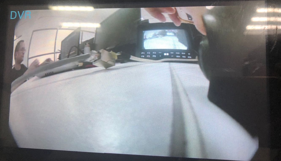
1.when i use the command "mxc_v4l2_tvin.out -ol 0 -ot 0 -ow 400 -oh 240 -d 1 -x 0" the screen will scroll

2.when i use the command " mxc_v4l2_tvin.out -ol 0 -ot 0 -ow 800 -oh 480 -d 1 -x 0 -g2d", the sreen show fliker
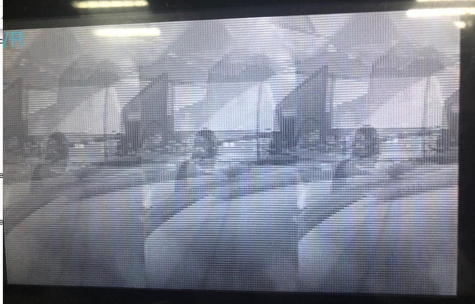
thank you very much .looking for you answer.
Hi Qiang Li,
Thanks.
The camera we verified on iMX8 is MAX9271+OV10635, but if you are using the MAX96705, you can reference to this iMX6 patch, there is only some small modifications for MAX96705.
Your failure means when MAX9286 try to access OV10635 with Coax cable (I2C signals are transfered on it), there is I2C access error, the I2C between MAX9286 and iMX8 has no error. There is is between MAX9286 and camera module. It is more like Coax signal issue.
Hi Qiang,
We use the LI-USB30-OV10635-SER connect to PC by usb 3.0, the capture show normal on tools, We think the ov10635 modules is OK.
max9286 driver load, max9286 can access by I2C, I2C driver I think is OK.
We doubt the configure of max9286 and max96705,Is this combination be worked on imx8x 4.9.51 version?
The I2C access issue is more like hardware issue, I think you need check your hardware.
The default iMX8 BSP supports MAX9286 directly, no patch is needed.
Hi Qiang,
I use max9286 and max96705+ov10635 on imx8x kernel version is 4.9.51, Does this version have patch?
Use the default max9286 driver which exist in kernel 4.9.51 source code,It show some error when driver load。
It seems ov10635 Communication failure by I2C, But the max9286 is success use the same I2C access
error log as below:
[ 2.525043] mxc-mipi-csi2 58227000.csi: mipi_csi2_probe
[ 2.549343] mxc-mipi-csi2 58227000.csi: lanes: 4, name: mxc-mipi-csi2.0
[ 2.556705] max9286_mipi 0-006a: In max9286_hardware_preinit()
[ 2.854197] max9286_mipi: reg = 0xf0.
[ 2.857870] max9286_mipi: sensor number = 4.
[ 2.862158] max9286_mipi 0-006a: In max9286_hardware_init()
[ 2.893273] max9286_mipi: initialized sensor = 0x01.
[ 2.921271] max9286_mipi: initialized sensor = 0x02.
[ 2.949272] max9286_mipi: initialized sensor = 0x03.
[ 2.977271] max9286_mipi: initialized sensor = 0x04.
[ 3.145279] max9286_mipi 0-006a: ov10635_read_reg:read reg error: reg=0x300a.
[ 3.152433] max9286_mipi 0-006a: ov10635_check_device: OV10635 hasn't been found, reg[0x300a] = 0x0., index=1
[ 3.321275] max9286_mipi 0-006a: ov10635_read_reg:read reg error: reg=0x300a.
[ 3.328419] max9286_mipi 0-006a: ov10635_check_device: OV10635 hasn't been found, reg[0x300a] = 0x0., index=2
[ 3.497275] max9286_mipi 0-006a: ov10635_read_reg:read reg error: reg=0x300a.
[ 3.504421] max9286_mipi 0-006a: ov10635_check_device: OV10635 hasn't been found, reg[0x300a] = 0x0., index=3
[ 3.673275] max9286_mipi 0-006a: ov10635_read_reg:read reg error: reg=0x300a.
[ 3.680420] max9286_mipi 0-006a: ov10635_check_device: OV10635 hasn't been found, reg[0x300a] = 0x0., index=4
[ 4.752679] max9286_mipi 0-006a: max9286_mipi is found, name max9286_mipi 0-006a
Could you help me which part error will lead to ov10635 access failure.
Hi Chris, if they are two MIPI CSI2 cameras, you can't connect them to CPU directly.
Hi Qiang,
This is great information! In the event that you want to use 2 CSI2 cameras, do you know if it's possible to hook both cameras directly to the processor (how do you handle the 2 clk pairs from the two cameras?) of if you need to use a signal aggregator to combine the cameras into one interface?
The MAX9286 needs all camera working at frame sync mode and same timing, so the cameras should send out vsync at almost same time. If some camera is working at free run mode, there will be scroll issue, because MAX9286 can't sync them.
You can measue the VSYNC for all cameras to check this.
i used the patch L3.10.53_GA1.1.0_MAX9286_Surroundview_Patch_2015-12-04.zip , when i connect 2 camera , i can capture image correctly. but when i connect three cameras i can not get image correctly, the image scroll.
I think you need check with Maxim for both the MAX9286 Programming Guider and the MAX9286 hardware schematics. From my point, the power supply to camera board with Coax cable is easy to cause such stable issue.
it like the signle is not stable , 70% it can work succefully ,the hard ware is designed according to the official schematic design.I am not sure where to check
would you please send the MAX9286 Programming Guide to me
The Max9286 setting is from "MAX9286 Programming Guide", I think you need check your hardware, if the MAX9286 can't lock the camera signals, it will not output valid MIPI CSI2 signal, then on iMX6 side, it will show "mipi csi2 can not receive sensor clk".
Hi li
i use max9286 and max96705
i found the connect is not very stable, sometime i get "mipi csi2 can not receive sensor clk..." ,when i git this error i fount all the config are success
i use the patch L3.10.53_GA1.1.0_MAX9286_Surroundview_Patch_2016-07-26.zip,
in the patch i found you config max9286 register 0x3f 0x3b ,but i did not found any introduction about these register ?
"ap0101_initialize:AP0101 is not in Host Configuration Mode"
This log means the camera is not in I2C config mode, so we can't initialize it. You need check your camera board, if it has flash on board, then you need update the flash ROM setting with the driver's. You can also remove the flash ROM on camera board, then the MAX9286 driver can initialize it with I2C commands.
Hi Lion,
You need include blank data too. So use the pixel clock to calculate the throughput is more simple and accuracy.
Hi Qiang
I also use ov10635, and use the same sensor register values as in your patch
the sensor output 1280*800@30fps with yuv422(uyvy,0x1e)
per my understanding, the camera data rate should be 30M*16bits=480Mbps
how to get the value of 768Mbps?
and in function mipi_csi2_reset, it just sets register MIPI_CSI_PHY_TST_CTL1,
from the name, it is just a test related register, is it useful for the mipi csi2 init?
thanks
Hi Lion Wei, the MAX throughput for IMX6 MIPI CSI2 is 3.2Gbps in 4 lanes mode, so each camera can be up to 800Mbps (include blank data).
And the followed code should be adjust for your real camera, the 768 should be your real camera bps:
/* 48MHz pixel clock (1280*800@30fps) * 16 bits per pixel (YUV422) = 768Mbps mipi data rate for each camera */
mipi_csi2_reset(mipi_csi2_info, (768 * g_sensor_num) / (lanes + 1));
Anoter limitation, at least 3 blank lines are needed for two frames from camera.
Hi Qiang
thanks for your help!
after tune the ti settings, I can receive four camera data now.
currently for 1/2/3 sensors, I can receive the data with correct pixels
however for 4 sensors, the pixel data has some line corruptions(see the below picture)
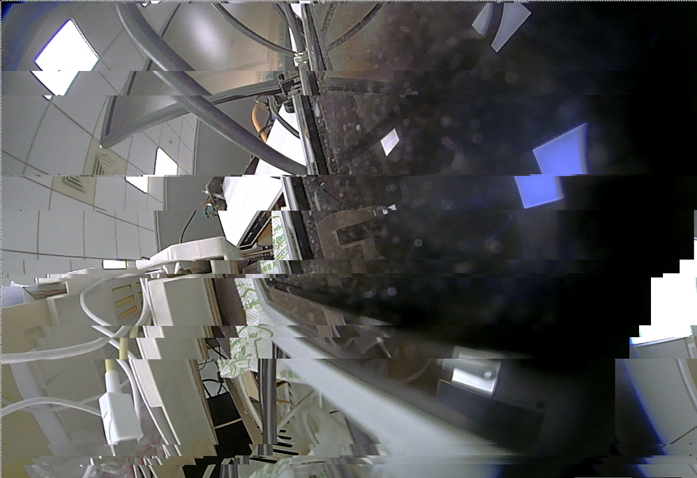
from TI side, we can set the data lane numbers and data lane rate
however, the data lane rate has only three options(400M, 800M, 1.6G)
with different rate+lane number setting, the 1/2/3 sensors can work perfectly
for 4 sensors, only 800M+4 data lanes works, but the data has some corruptions
my question is
1) for imx6 mipi csi2 receiver, is there any special requirement on the rate and data lanes setting?
2) for imx6 mipi csi, what is the suitable ratio between the real data rate and the total data capability?
2) any suggestions?
Hi Mustafa,
These packages are implemented by the MIPI CSI2 hardware, from software side, we just tell it the virtual channel number and Data Identifier (It can be found at include\linux\mipi_csi2.h).
Thank you for respond Qiang_FSL
I am now looking at the MIPI CSI2 Reference Documentation , I am checking all. Also I made search on the my imx6q(Wandboard Quad) custom board source and header files. After my research I could not find relative source code in the my kernel files, which defines packet types and communication sub-structures for CSI-2 Interface Low Level Protocol message protocol , SoT and EoT package sample codes. I will take the video by using "mxc" relative files and it's ipu source codes. So If you can share any source code or any relative codes which informs me about SoT,EoT and LLP Massage Package Structures sample codes, It would be very nice and useful for me because I don't have any reference code in my kernel files.
Best Regards.
Hi Lion,
The MIPI CSI2 error registers can be used to check the MIPI CSI2 package is correct with CRC or follows the protocol.
Hi Mustafa, the information can be found from MIPI CSI2 specification:
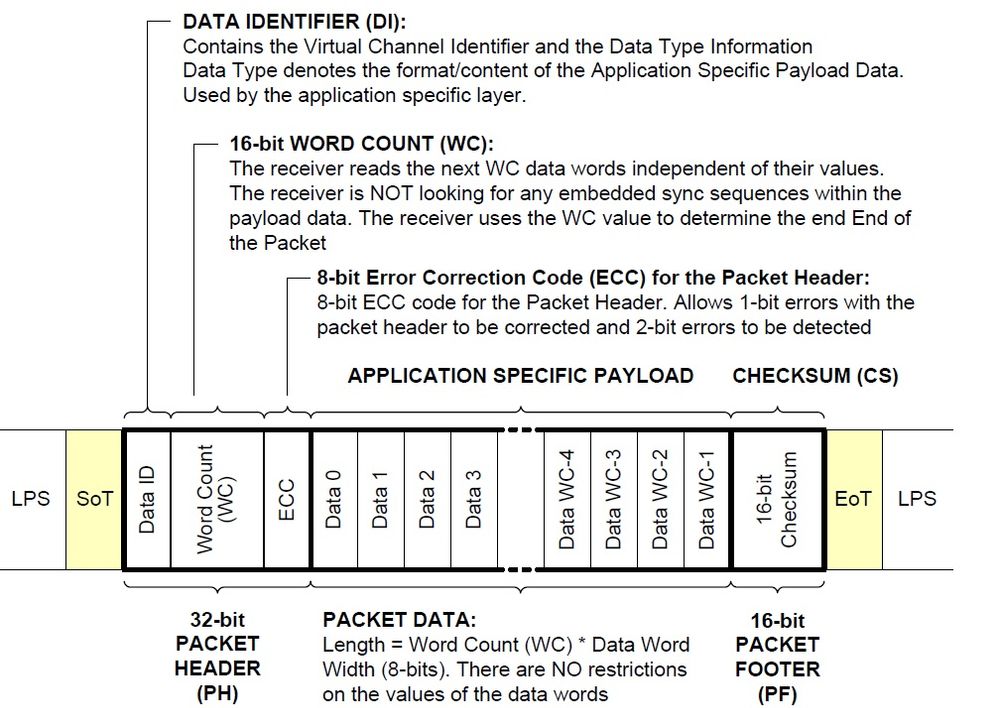
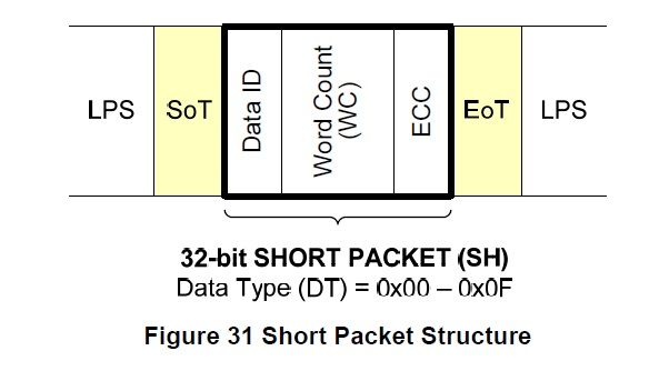
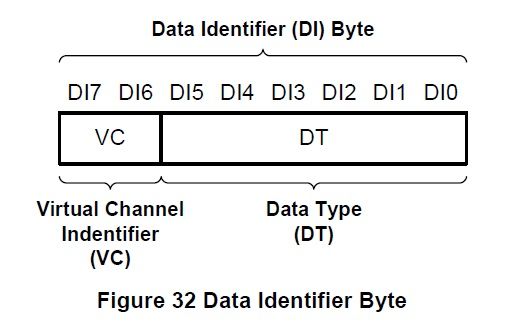
According to iMX6 CSI2IPU documentation we need to create short or long type packages and also we need Start Of Transmission and End Of Transmission packages too,
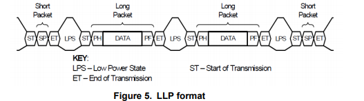
How can I send this packages for example in the camera device driver source this packages should be created and sent these data types or we are defining these values to another files . What is the format of SoT and EoT packages?
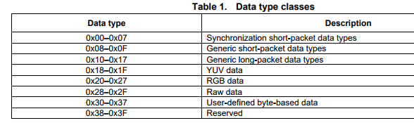
Can someone give me any example about that, I have been working to solve the csi2 format mipi clock and data lane problem, I couldnt define to the iMX6Q processor custom board since 3 week. It would be very very appreciated.
Best Regards
Hi Qiang
is there any way on imx6 to confirm the mipi data correct or not from mipi csi-2?
for example some register show the status of the mipi csi-2, specially the virtual channel/frame size related
Hi Lion, no special modification is needed on iMX6 side, you should tune the Ti chip setting.
As I know, some customer had already make the Ti 964 work on iMX6 platform, the main work is in Ti side, you should check with them. For iMX6, you just need make sure the four cameras is transfered on 4 MIPI virtual channel.
Hi Qiang
I am using following hardwares for similiar surroundview implementation under linux 3.14.52
ov10635 <--> ds90ub913 <-->
ov10635 <--> ds90ub913 <--> DS90ub964-q <-----> imx6q
ov10635 <--> ds90ub913 <-->
ov10635 <--> ds90ub913 <-->
the driver patches are most the same as the one you provided
and currently the mipi-csi2 can detect the pixclock successfully
also the waves on the data lines of mipi-csi2 seems correctly
however, I can not receive the camera_callback for camera 0-2, only can receive camera_callback of camera 3
I have read all the comments above, and can not find the similiar causes
I have checked the following things
1) the MIPI_IPU1_MUX and MIPI_IPU2_MUX are set to 0 for mipi_csi
2) the register dumps:
IPU1_CSI0_SENSE_CONF(0x2630000): 0x04008a00
IPU1_CSI1_SENSE_CONF(0x2638000): 0x04008a00
IPU2_CSI0_SENSE_CONF(0x2a30000): 0x04008a00
IPU2_CSI1_SENSE_CONF(0x2a38000): 0x04008a00
IPU1_IDMAC_CH_EN_1(0x2608004): 0x00000003
IPU1_IDMAC_CH_EN_2(0x2608008): 0x00000000
IPU2_IDMAC_CH_EN_1(0x2a08004): 0x00800003
IPU2_IDMAC_CH_EN_2(0x2a08008): 0x00000000
IPU1_IDMAC_CH_BUSY_1(0x2608100): 0x00000003
IPU2_IDMAC_CH_BUSY_1(0x2a08100): 0x00800002
IPU1_SMFC_MAP(0x2650000): 0x00000020
IPU2_SMFC_MAP(0x2a50000): 0x00000020
my questions are
1) are the smfc and idmac setting correct for these four cameras?
2) from the spec, it says ipu mipi should use non-gated mode, but mxc_v4l2_capture.c uses gated mode in mxc_v4l2_s_param
which mode should I use(I have tried both modes, and neither of them works for me)
3) which case need me to set the hsync_pol, vsync_pol?
4) any suggestion to identify this issue?
thanks
That means your kernel is not aligned with the GPU libs in your rootfs.
Hi Qiang,
Have a nice holiday. I have some trouble with my borad. We refer to the sabresd and max9286+max96705+ap 0101, and we used the 3.14.52 BSP. Now our four camera are all working properly, but when I used '-g2d' in the test command there is a error just like 'Segmentation fault'. I think It may be something wrong with my GPU,but I don't kown how to deal with the problem. Could you give some advices to me ?Thanks . Here is the log below.
root@imx6qdlsolo:~# ./mxc_v4l2_tvin.out -ol 0 -ot 0 -ow 960 -oh 540 -d 0 -x 0
------------------------------here is AP0101--------------------------------
max9286_mipi: sensor number = 4.
mxc_mipi_csi2 21dc000.mipi_csi: mipi_csi2_reset: mipi_lane_bps = 594 Mbps
mxc_mipi_csi2 21dc000.mipi_csi: mipi_csi2_reset: value = 0x2e.
max9286_mipi 1-006a: ap0101_initialize: AP0101 was found, index = 1.
max9286_mipi 1-006a: ap0101_initialize:AP0101 is already in Slave (Shutter-Sync) Mode.
max9286_mipi 1-006a: ap0101_initialize: AP0101 was found, index = 2.
max9286_mipi 1-006a: ap0101_initialize:AP0101 is already in Slave (Shutter-Sync) Mode.
max9286_mipi 1-006a: ap0101_initialize: AP0101 was found, index = 3.
max9286_mipi 1-006a: ap0101_initialize:AP0101 is already in Slave (Shutter-Sync) Mode.
max9286_mipi 1-006a: ap0101_initialize: AP0101 was found, index = 4.
max9286_mipi 1-006a: ap0101_initialize:AP0101 is already in Slave (Shutter-Sync) Mode.
g_in_width = 1280, g_in_height = 720.
fb_fix.id = DISP4 BG.
It is background screen, only full screen default format was supported.
fb: smem_start = 0x25600000, smem_len = 0x546000.
fb: frame buffer size = 0x1c2000 bytes.
fb: g_screen_info.xres = 1280, g_screen_info.yres = 720.
fb: g_display_left = 0.
fb: g_display_top = 0.
fb: g_display_width = 1280.
fb: g_display_height = 720.
start time = 1449238585 s, 124037 us
^CERROR: v4l2 capture: mxc_v4l_dqueue() interrupt received
root@imx6qdlsolo:~# ./mxc_v4l2_tvin.out -ol 0 -ot 0 -ow 960 -oh 540 -d 0 -x 0 -g2d
------------------------------here is AP0101--------------------------------
max9286_mipi: sensor number = 4.
mxc_mipi_csi2 21dc000.mipi_csi: mipi_csi2_reset: mipi_lane_bps = 594 Mbps
mxc_mipi_csi2 21dc000.mipi_csi: mipi_csi2_reset: value = 0x2e.
max9286_mipi 1-006a: ap0101_initialize: AP0101 was found, index = 1.
max9286_mipi 1-006a: ap0101_initialize:AP0101 is already in Slave (Shutter-Sync) Mode.
max9286_mipi 1-006a: ap0101_initialize: AP0101 was found, index = 2.
max9286_mipi 1-006a: ap0101_initialize:AP0101 is already in Slave (Shutter-Sync) Mode.
max9286_mipi 1-006a: ap0101_initialize: AP0101 was found, index = 3.
max9286_mipi 1-006a: ap0101_initialize:AP0101 is already in Slave (Shutter-Sync) Mode.
max9286_mipi 1-006a: ap0101_initialize: AP0101 was found, index = 4.
max9286_mipi 1-006a: ap0101_initialize:AP0101 is already in Slave (Shutter-Sync) Mode.
g_in_width = 1280, g_in_height = 720.
fb_fix.id = DISP4 BG.
fb: smem_start = 0x25600000, smem_len = 0x546000.
fb: frame buffer size = 0x1c2000 bytes.
fb: g_screen_info.xres = 1280, g_screen_info.yres = 720.
fb: g_display_left = 0.
fb: g_display_top = 0.
fb: g_display_width = 960.
fb: g_display_height = 540.
Segmentation fault
With my best regards
Jun
Hi Yu fe,
This error means MAX9286 can't detect the cameras, you need check your hardware signal and power between MAX9286 and MAX96705.
hi, Qiang Li
my custom board is ref to saresd, max9286+max96705+ap010.
my yocto version is 3.14.52, i got message below after patched the kernel
pr_info("max9286_mipi: sensor number = %d.\n", g_sensor_num);
if (g_sensor_num == 0) {
pr_err("%s: no camera connected.\n", __func__);
return -1;
}
can you please give me some suggestion to find the program?
When you used IPU for CSC on 1280*720 frames, the IPU loading is heavy, there is chance that IPU can't service the capture on time.
To improve it, you need use IDMAC 0 and IDMAC 2, then all FIFO can be used:
In ipu_common.c, function ipu_probe(), please make sure all CSI->MEM channels are set to high priority:
/* Set sync refresh channels and CSI->mem channel as high priority */
- ipu_idmac_write(ipu, 0x18800003L, IDMAC_CHA_PRI(0));
+ ipu_idmac_write(ipu, 0x1880000FL, IDMAC_CHA_PRI(0));
This file can be found from your rootfs.
Hello Qiang,
The attached tvin source code includes a local file #include "g2d.h". However this file is not included in the archive. Where do we get this file?
4 in 1 HD recorder resolved?
Hi Brave,
That error means there is no valid MIPI CSI2 signal to IMX6, from your log, it seems there is flash in your camera module, if so, the flash setting for the camera should be algined with the AP0101 setting in max9286.c, the camera should work in frame sync mode.
On Max9286, there is a lock pin, only when the four cameras are working in frame sync mode and are locked by MAX9286, it will output valid MIPI CSI2 signal to iMX6.
Dear Qiang Li, could you please kindly take a look at following post and give me an insight ?
Adding X11 Interlace Video Mode Support to Yocto
Thanks in Advance
Anuradha
The iMX6 SabreAuto board can only supply 5V power to MAX9286 board, so if you are using long Coax cable, there will be issue. You can rework your MAX9286 board, and supply 7~12V power to it.
"MAX9296 + 4 96705 +4camera" the reference patch had already covered this, the sync setting is in camera and Maxim chip side.
Hi Qiang,
How to sync the camera of the MAX9296 + 4 96705 +4camera?
We have 2 customer want to use the IMX.6 + MAX9268+ 4 MAX96705---camera. Could you suggest how to sync the camera?
Thank you very much.
Hi Li,
Why do I need to set video format to 4 (UYVY) when using grecorder tool?
now i try use h.264,
./mxc_vpu_test.out -E "-x 0 -f 0 -c 1800 -a 30 -w 1280 -h 792 -o ss.mp4 -l 0 -b 5204"
when i try to play ss.mp4 on PC i can't play it normally, like the mp4 file has no header,
how to create a mp4 file when use H.264 recoder video data?
Hi, Li
now i try to use VPU to encode the camera data, i use MJPEG, i do not want to use other standed (H263 H264),
the the file is a too large, 100 frames will make a file about 11M.
how to reduce MJPEG file?
thanks
Dear Qiang!
I am using MAX9286+OV10635+MAX9271. I have tested 3.10.53patch and 3.14.52patch, but both of them are not work. When I ran "/mxc_v4l2_tvin.out -ol 0 -ot 0 -ow 960 -oh 540 -d 1 -x 0 -g2d &". I got the same errors, like this
[ 2027.062578] max9286_mipi 0-0048: max9286_write_reg reg = 0x15, val = 0x13.
[ 2027.070238] max9286_mipi 0-0048: max9286_write_reg reg = 0xe, val = 0x5f.
root@wandboard-quad:/usr/src# [ 2027.093488] max9286_mipi 0-0048: max9286_write_reg reg = 0x3f, val = 0x4f.
[ 2027.113488] max9286_mipi 0-0048: max9286_write_reg reg = 0x3b, val = 0x1e.
[ 2027.332778] max9286_mipi 0-0048: max9271_write_reg:write reg error:reg= 4,val=43
[ 2027.552770] max9286_mipi 0-0048: max9271_write_reg:write reg error:reg= 8,val= 1
[ 2027.573473] max9286_mipi 0-0048: max9286_write_reg reg = 0x3b, val = 0x19.
[ 2027.593452] max9286_mipi 0-0048: max9286_write_reg reg = 0x12, val = 0xf3.
[ 2027.601029] max9286_mipi 0-0048: max9286_write_reg reg = 0x1, val = 0x2.
[ 2027.713713] max9286_mipi: sensor number = 1.
[ 2027.718679] max9286_mipi 0-0048: max9286_write_reg reg = 0xe, val = 0x50.
[ 2027.728809] max9286_mipi 0-0048: max9286_write_reg reg = 0xb, val = 0xe1.
[ 2027.735691] mxc_mipi_csi2 21dc000.mipi_csi: mipi_csi2_reset: mipi_lane_bps = 192 Mbps
[ 2027.744033] mxc_mipi_csi2 21dc000.mipi_csi: mipi_csi2_reset: value = 0x44.
[ 2027.751624] max9286_mipi 0-0048: max9286_write_reg reg = 0x0, val = 0xe2.
[ 2027.760490] max9286_mipi 0-0048: max9286_write_reg reg = 0xa, val = 0x22.
[ 2027.962765] max9286_mipi 0-0048: max9271_write_reg:write reg error:reg= 0,val= 4
[ 2028.182767] max9286_mipi 0-0048: max9271_write_reg:write reg error:reg= 7,val=84
[ 2028.402761] max9286_mipi 0-0048: max9271_write_reg:write reg error:reg= 1,val=90
[ 2028.602752] max9286_mipi 0-0048: max9271_write_reg:write reg error:reg= 9,val=c4
[ 2028.802767] max9286_mipi 0-0048: max9271_write_reg:write reg error:reg= a,val=c0
[ 2029.002791] max9286_mipi 0-0048: max9271_write_reg:write reg error:reg= b,val= a
[ 2029.202766] max9286_mipi 0-0048: max9271_write_reg:write reg error:reg= c,val= 4
[ 2029.223462] max9286_mipi 0-0048: max9286_write_reg reg = 0xa, val = 0x22.
[ 2029.230955] max9286_mipi 0-0048: max9286_write_reg reg = 0xa, val = 0xff.
[ 2029.432766] max9286_mipi 0-0048: max9271_write_reg:write reg error:reg= 4,val=43
[ 2029.441134] max9286 reg 0x0A = 0xff.
[ 2029.447266] max9286_mipi 0-0048: max9286_write_reg reg = 0x34, val = 0x36.
[ 2029.652766] max9286_mipi 0-0048: max9271_read_reg:read reg error: reg= 4
[ 2029.659488] max9271 reg 0x04 = 0xffffffff.
[ 2029.862766] max9286_mipi 0-0048: max9271_read_reg:read reg error: reg= 4
[ 2029.869489] max9271 reg 0x04 = 0xffffffff.
[ 2030.072766] max9286_mipi 0-0048: max9271_read_reg:read reg error: reg= 4
[ 2030.079487] max9271 reg 0x04 = 0xffffffff.
[ 2030.282776] max9286_mipi 0-0048: max9271_read_reg:read reg error: reg= 4
[ 2030.289497] max9271 reg 0x04 = 0xffffffff.
[ 2030.492792] max9286_mipi 0-0048: ov10635_read_reg:read reg error: reg=0x300a.
[ 2030.499957] max9286_mipi 0-0048: ov10635_check_device: OV10635 hasn't been found, reg[0x300a] = 0x0.
[ 2030.510196] max9286_mipi 0-0048: max9286_write_reg reg = 0x34, val = 0xb6.
[ 2030.712770] max9286_mipi 0-0048: max9271_write_reg:write reg error:reg= 4,val=83
[ 2030.823490] max9286_mipi 0-0048: max9286_write_reg reg = 0x15, val = 0x9b.
[ 2031.442763] mipi csi2 can not receive sensor clk! MIPI_CSI_PHY_STATE = 0x200.
g_in_width = 1280, g_in_height = 800.
fb_fix.id = DISP3 FG.
fb: smem_start = 0x40800000, smem_len = 0xa8c000.
fb: frame buffer size = 0x384000 bytes.
fb: g_screen_info.xres = 1280, g_screen_info.yres = 720.
fb: g_display_left = 0.
fb: g_display_top = 0.
fb: g_display_width = 960.
fb: g_display_height = 540.
start time = 1499055466 s, 40751 us
[ 2041.482836] ERROR: v4l2 capture: mxc_v4l_dqueue timeout enc_counter 0
VIDIOC_DQBUF failed.
It shows that can't find OV10635 and MAX9271. If there are something wrong with I2C drivers?
I can confirm my hardware board is OK, because I am using the "MAX9286 COAX EVKIT" board.
Could you help me?
3.14.52 BSP release has this tool. For other release, it is same as normal camera recode.
where can i get grecorder-1.0
VPU performance is not enough for 4x720P30 recoder.
For one camera:
grecorder-1.0 --camera_id 0 --video_format 4 --width1280 --height 720 --fps 30
Hi li
How to use gstreamer record the four channel camera data?
where should i change the ipu driver code?like csi_enc_setup in ipu_csi_enc.c ,and camera_callback in mxc_v4l2_capture.c
You can alloc a big buffer array for V4l2 capture driver with 2560*1440 pixel buffers:
For camera 1, let its DMA buffer base address to pixel (0, 0), width 1280, height 720, but set the stride to 1280*2*2; then after filled 1280 pixels (1280*2 bytes for UYVY input), it will jump 1280*2*2 bytes; so camera 1 will fill the left-up 1280*720 pixels of the buffer;
For camera 2, let its DMA buffer base address to pixel (1280, 0), width 1280, height 720, but set the stride to 1280*2*2; then after filled 1280 pixels (1280*2 bytes for UYVY input), it will jump 1280*2*2 bytes; so camera 2 will fill the right-up 1280*720 pixels of the buffer;
For camera 3, let its DMA buffer base address to pixel (0, 720), width 1280, height 720, but set the stride to 1280*2*2; then after filled 1280 pixels (1280*2 bytes for UYVY input), it will jump 1280*2*2 bytes; so camera 3 will fill the left-down 1280*720 pixels of the buffer;
For camera 4, let its DMA buffer base address to pixel (1280, 720), width 1280, height 720, but set the stride to 1280*2*2; then after filled 1280 pixels (1280*2 bytes for UYVY input), it will jump 1280*2*2 bytes; so camera 4 will fill the right-down 1280*720 pixels of the buffer.
i want to put the four Independent camera data together in the ipu driver like one of below image , so then user can just use once DQBUF call to get all the four camera data.

or

Please check with your S32V contact window for that, here is just for IMX6.
I think you still need check and tuning your ISX016 camera setting, the reference code is for AP0101+AR0140 camera board.
mxc_mipi_csi2 21dc000.mipi_csi: mipi_csi2_reset: mipi_lane_bps = 336 Mbps
mxc_mipi_csi2 21dc000.mipi_csi: mipi_csi2_reset: value = 0x2a.
max9286_mipi 1-006a: ap0101_initialize: AP0101 was found, index = 1.
max9286_mipi 1-006a: ap0101_initialize:AP0101 is already in Slave (Shutter-Sync) Mode.
max9286_mipi 1-006a: ap0101_initialize: AP0101 was found, index = 2.
max9286_mipi 1-006a: ap0101_initialize:AP0101 is already in Slave (Shutter-Sync) Mode.
I think your cameras are not working in sync mode. They should work in such mode: MAX9286 send a pulse to each camera, then each camera send out one frame. The VSYNC for each camera should appear in almost same time.
If MAX9286 can't sync the multi-cameras, it will not output MIPI signals. But for single camera, no sync was needed.
now i use BSP 3.10.53, max9286+max96707+ISX016
when connest one camera i can get image successfully,but when i connect tow cameras i always get mipi csi2 can not receive sensor clk! MIPI_CSI_PHY_STATE = 0x6f0.
i have patched L3.10.53_GA1.1.0_MAX9286_Surroundview_Patch_2016-07-26.zip
my code :
max9271_write_reg(0, 0x40, 0x2F);
msleep(2);
max9271_write_reg(0, 0x97, 0x5F);
....
max9286_write_reg(0x01, 0x00);
max9286_write_reg(0x63, 0x00);
max9286_write_reg(0x64, 0x00);
max9286_write_reg(0x06, 0x00);
max9286_write_reg(0x07, 0x00);
max9286_write_reg(0x08, 0x26);
...
mipi_csi2_reset(mipi_csi2_info, (576 * g_sensor_num) / (lanes + 1));
i have refer Debug steps for customer MIPI sensor.docx.
my doubt is how to confirm hsp_clk and ccm_pixel_clkm and where to configure hsp_clk and ccm_pixel_clkm?
another question is about MAX9286 (FSYN CLOCKED in register 0x31 ) when i read it it is 0x0, if the two camera can not get FSYNC LOCKED, this will lead to can not receive sensor clk???
how to fix this?
thanks
Thanks. The problem has been resoved.
Reference to MIPI specification, the YUV422 data transferred on MIPI CSI2 is UYVY, no YUYV, so in max9286_mipi.c, we have the followed code:
max9286_data[0].pix.pixelformat = V4L2_PIX_FMT_UYVY;
if (sensor->pix.pixelformat == V4L2_PIX_FMT_UYVY) {
for (i=0; i
If your camera can only be YUYV format, you should change the max9286_mipi.c as followed:
max9286_data[0].pix.pixelformat = V4L2_PIX_FMT_YUYV;
if (sensor->pix.pixelformat == V4L2_PIX_FMT_YUYV) {
for (i=0; i
Note: MIPI_DT_YUV422 can't be changed, it is defined by MIPI CSI2 specification for UYVY, there is no MIPI data type for YUYV.
The patch had already show you the reference code to set the GPR register in file arch/arm/mach-imx/mach-imx6q.c.
You need check your kernel boot up log to confirm there is no other V4l2 capture driver used video0. You can also use command "ls /dev/video*" to list all video device in your system.
And register IOMUXC_GPR1 (0x020E0004) should also be checked, bit 20 and bit 19 must be 0.
(1) Onsemi AR0140+AP0101+MAX9271 boards.
We got this board from Onsemi.
(2) OmniVision OV10635+MAX9271 boards.
This board is made by Maxim, you can check with them.
And as I know AVNET China team had also built some camera boards for both AR0140 and OV10635.
"http://entroninc.com/" had also built camera boards for this solution.
I want to get your Test camera board
(1) Onsemi AR0140+AP0101+MAX9271 boards.
(2) OmniVision OV10635+MAX9271 boards.
where can I get them?
Could you please recommend
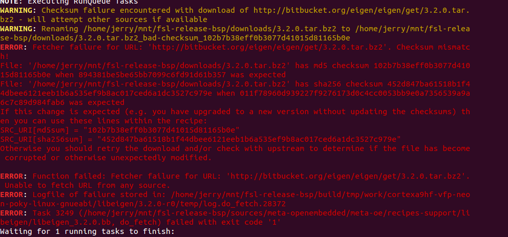
Hi Li, when i build BSP L3.14.52.1.1,i got some error, please give some help,thanks
bitback fsl-image-gui
Thanks for your reply. There is no flash ROM on OV10635 board.
Follow are the wave of FSIN,HRFE and VSYNC. I think the issure in the OV10635 register setting, My OV10635 is producted in 2014, did you test the patch on the 2014 version chip and have the correct register setting?
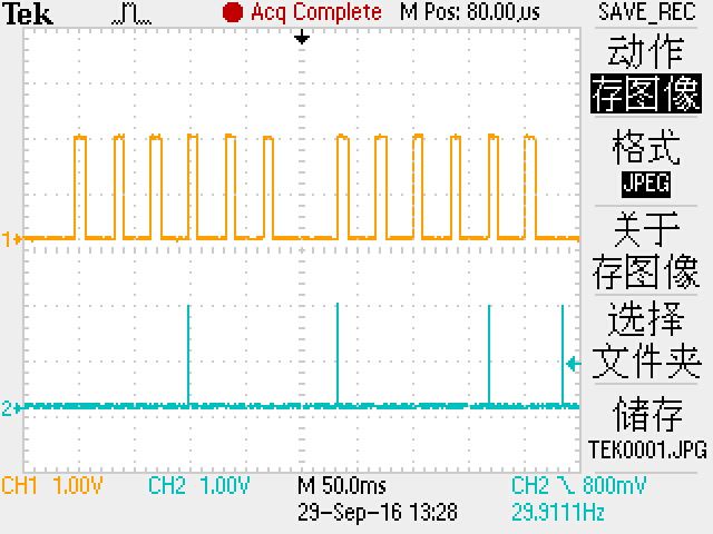
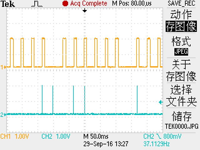
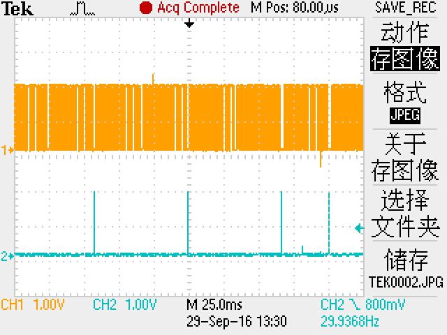
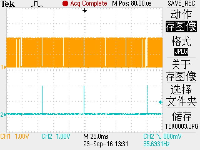
Coment:yellow is HREF, blue is VSYNC.
Hi Qiang,
The patch of HD 720p sound view we have tested on I.MX6qp-sabreauto .But now our board designed based on I.mx6qsabresd and BSP version is L3.14.52 for imx6qsabresd. So ,my question is can you send us the patch for L3.14.52 of imx6qsabresd ?
Hi Winter, did you measure the correct pin? The HREF is the HSYNC signal, it is for line, so it will not be 30fps.
I think you need check your OV10635 setting, if it is initialized by on board flash ROM, not from the MAX9286 driver, you should update your flash ROM setting. The VSYNC should align with the FSIN signal, this signal is from MAX9271's GPO. One FSIN, one VSYNC.
Hi~Li Qiang!
Thank you for your Patch~
I use your patch for my camera OV10635 board, it is not work. I found the VSYNC of the OV10635 is discontinuous,the HREF is ok and looks about 30fps. Can you paste your VSYNC wave here? Thanks
The camera sensor AR0140 should connect to ISP AP0101, then AP0101 should connected to MAX9271 to output the serial signal.
And I think, without AP0101, the AR0140 can't work in the solution.
hi Li Qiang:
have change the config,But i find i your code only have AP0101,not have AR0140,i run the board,like this:
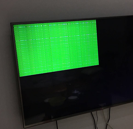
Please read the readme file again, it had already told you where to select the camera sensor.
hi Li qiang:
i find my sensor is AR0140,not OV10635,Where I need to change?thank you
Hi Haifeng, yes the MAX9286 board was powered from iMX6 board with 5V power, and the OV10635 camera boards can also be powered from iMX6 boards's 5V, but there is another power connector on MAX9286 board which can be used to power the 4xOV10635 camera board, you can connect 12V power to it and select the jump on MAX9286 boards.
So the final power: 5V from iMX6 board to MAX9286 board; 12V from MAX9286 board's power connector to OV10635 camera boards.
hi qiang li:
i use the MAX9286 board,i find the max9286 board supply by 5V, my max9286board supply by maxim,they designed for I.mx6.

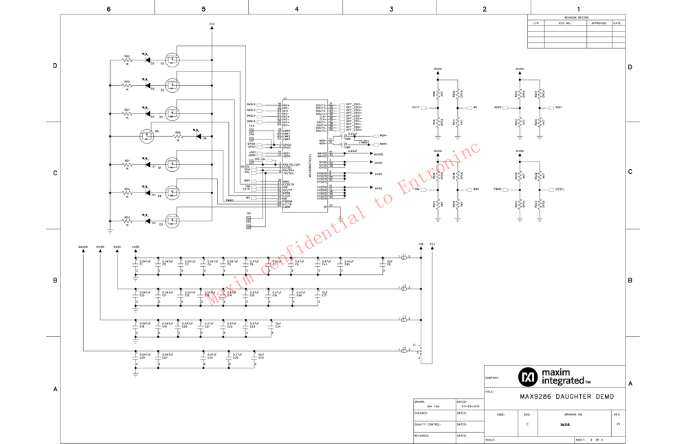
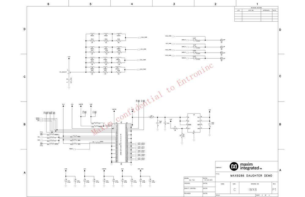
These setting are used in mxc_mipi_csi2.c and mxc_v4l2_capture.c, you can modify the code directly.
By the way, I think you should not compare the patched 3.10.53 files with 3.0.35 files, you can manually modify the 3.0.35 files directly, based on the code modification in patches.
inux_3.10.35/arch/arm/boot/dts/imx6q-sabreauto.dts 中
&mipi_csi {
status = "okay";
lanes = <4>;
mipi-csi2-channel@0 {
ipu_id = <0>;
csi_id = <0>;
v_channel = <0>;
status = "okay";
};
mipi-csi2-channel@1 {
ipu_id = <0>;
csi_id = <1>;
v_channel = <1>;
status = "okay";
};
mipi-csi2-channel@2 {
ipu_id = <1>;
csi_id = <0>;
v_channel = <2>;
status = "okay";
};
mipi-csi2-channel@3 {
ipu_id = <1>;
csi_id = <1>;
v_channel = <3>;
status = "okay";
};
};
这一段在3.0.35中怎么处理?
Hi Jin, if you supply the camera board with 5V power and using long Coax cable, there is chance to get such issue.
The OV10635 camera board is designed for 7~12V power supply, so you can supply the camera board with 12V power.
dear Qiang Li:
have you try on the imx6q-sabreauto board? i can not use the max9286 on sabreauto board,it is some error:
1 -x 0 -g2d &lo:/unit_tests# ./mxc_v4l2_tvin.out -ol 0 -ot 0 -ow 960 -oh 540 -d
[1] 845
root@imx6qdlsolo:/unit_tests# max9286_mipi: sensor number = 1.
mxc_mipi_csi2 21dc000.mipi_csi: mipi_csi2_reset: mipi_lane_bps = 192 Mbps
mxc_mipi_csi2 21dc000.mipi_csi: mipi_csi2_reset: value = 0x44.
max9286_mipi 1-006a: ov10635_read_reg:read reg error: reg=0x300a.
max9286_mipi 1-006a: ov10635_check_device: OV10635 hasn't been found, reg[0x300a] = 0x0.
mipi csi2 can not receive sensor clk! MIPI_CSI_PHY_STATE = 0x6f0.
g_in_width = 1280, g_in_height = 800.
fb_fix.id = DISP4 FG.
fb: smem_start = 0x73600000, smem_len = 0x480000.
fb: frame buffer size = 0x180000 bytes.
fb: g_screen_info.xres = 1024, g_screen_info.yres = 768.
fb: g_display_left = 0.
fb: g_display_top = 0.
fb: g_display_width = 960.
fb: g_display_height = 540.
You can link the libg2d.so to libg2d.so.0.8.
dear Qiang Li:
i have use the L3.14.52,it is some error use the binary in mxc_v4l2_tvin_max9286.tar.gz which yours,the log :
./mxc_v4l2_tvin.out: error while loading shared libraries: libg2d.so.0.8: cannot open shared object file: No such file or directory
There is binary file in mxc_v4l2_tvin_max9286.tar.gz, you can use it directly.
Hi Qiang Li
i use de 3.14.52,all patch used,but i have not use,mxc_v4l2_tvin_max9286.tar.gz,in the rootfs,i use unit_tests/mxc_v4l2_tvin.out ,it is nothing to display,can you help me?in the 3.14.52 yocto ,i can not complie the mxc_v4l2_tvin_max9286.tar.gz ,it is something wrong
After commented out adv7180, it became OK.
Hi Qiang Li
I see.
the adv7180 should be commented out in imx6qdl-sabreauto.dtsi file.
Thank you!
ZongbiaoLiao
From your log "g_in_width = 720, g_in_height = 624", I think the IPU0 CSI0 port hasn't been used by the MAX9286, it is still combined with adv7180.
Hi Qiang Li
The log is as bellow:
---------------------------------------
root@imx6qsabreauto:/unit_tests# ./max9286.sh
root@imx6qsabreauto:/unit_tests# g_in_width = 1280, g_in_height = 800.
fb_fix.id = DISP3 FG.
g_in_width = 1280, g_in_height = 800.
g_in_width = 1280, g_in_height = 800.
fb: smem_start = 0x72c00000, smem_len = 0xbdd800.
fb_fix.id = DISP3 FG.
fb: frame buffer size = 0x3f4800 bytes.
fb: g_screen_info.xres = 1920, g_screen_info.yres = 1080.
fb: g_display_left = 960.
fb: g_display_top = 0.
fb: g_display_width = 960.
fb: g_display_height = 540.
fb: smem_start = 0x72c00000, smem_len = 0xbdd800.
start time = 1457509993 s, 697691 us
fb: frame buffer size = 0x3f4800 bytes.
fb: g_screen_info.xres = 1920, g_screen_info.yres = 1080.
fb: g_display_left = 0.
fb: g_display_top = 540.
fb_fix.id = DISP3 FG.
fb: g_display_width = 960.
fb: g_display_height = 540.
fb: smem_start = 0x72c00000, smem_len = 0xbdd800.
fb: frame buffer size = 0x3f4800 bytes.
fb: g_screen_info.xres = 1920, g_screen_info.yres = 1080.
fb: g_display_left = 960.
fb: g_display_top = 540.
fb: g_display_width = 960.
fb: g_display_height = 540.
start time = 1457509993 s, 717597 us
start time = 1457509993 s, 717698 us
g_in_width = 720, g_in_height = 624.
fb_fix.id = DISP3 FG.
fb: smem_start = 0x72c00000, smem_len = 0xbdd800.
fb: frame buffer size = 0x3f4800 bytes.
fb: g_screen_info.xres = 1920, g_screen_info.yres = 1080.
fb: g_display_left = 0.
fb: g_display_top = 0.
fb: g_display_width = 960.
fb: g_display_height = 540.
start time = 1457509994 s, 45827 us
ERROR: v4l2 capture: mxc_v4l_dqueue timeout enc_counter 0
VIDIOC_DQBUF failed.
------------------------------------------------------
and what the HDMI display showed is as bellow:
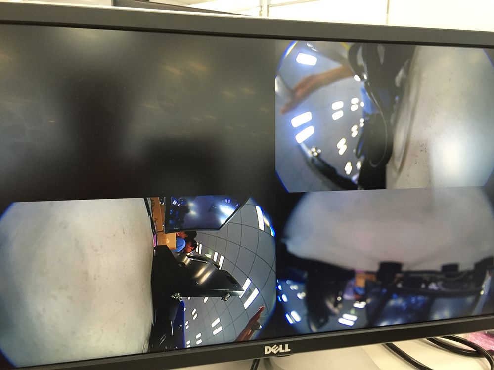
The first camera shows nothing and after several seconds the 'ERROR: v4l2 capture: mxc_v4l_dqueue timeout enc_counter 0' is output,
all other three cameras also stop and show nothing.
Thank you!
ZongbiaoLiao
What's the error log?
Hi, Qiang Li
I selected MAX9271.
My problem is three cameras work except the first one.
Thank you!
ZongbiaoLiao
You need select MAX96705 or MAX9271 in the kernel config, if it is different with your hardware, it will not work.
Hi Qiang Li
Thank you for releasing patch for L3.14.52_GA1.1.0.
I have tested the patch,but I met a problem.
The first camera(mxc_v4l2_tvin.out -ol 0 -ot 0 -ow 960 -oh 540 -d 1 -x 0 -g2d &) does not show anything,
and after several seconds, error 'VIDIOC_DQBUF failed' happened,all other three cameras also stopped.
Then I tested patch for 3.10.53,all cameras have no problem.
Could you help me?
Thank you!
ZongbiaoLiao
We have no plan to back porting the driver to 3.0.35 BSP, please do it by yourself. Thanks!
Hi~Li Qiang!
Thank you for your Patch~
But our cpu is IMX6Q-Sabresd, Camera is Ov10635. LTIB is L3.0.35_4.1.0
Can you help me support this Patch ?
Thanks Sincerely~~
FRSYNC/GPI does not need to be connected to iMX6, and CSI0_MCLK is not used. All working mode settings are between MAX9286 and camera, so you need to confirm with Maxim about the specific connection settings between MAX9286 and Camera (AP0101). For iMX6, you only need to connect the data and clock of MIPI CSI2.
If the working mode of MAX9286 and Camera is not correct, the data coming from MIPI will be abnormal.
Thank you very much. The problem of video0 not displaying has been solved. Now there is another problem, that is, the YUV data obtained through the mxc_v4l2_tvin_max9286 process is always reversed. For example, I set g_in_fmt = V4L2_PIX_FMT_UYVY in my application, and the data viewed in capture_buffers is actually YUYV. If g_in_fmt = V4L2_PIX_FMT_YUYV, the data viewed in capture_buffers is actually UYVY. I configured the CSI data format YUYV and UYUV by changing CSI0_SENS_DATA_FORMAT, but it didn't work. Is this modification correct? What causes this problem?
Boss, didn't you adjust it on version 3.0.35 before? Please share with us.
Supplement: The sensor I use is ov490 (isp) + ov10640 (sensor), and the data format output by the sensor is YUV422---YUYV.
Hello! Thanks for your reply!
First of all, the high and low data lines from the camera to the MAX96705 are indeed reversed, but we only connected 8 data lines instead of 10. The picture shown above is the image after the data lines are reversed. The specific settings are as follows:
max9271_write_reg(i, 0x20, 0x07);
max9271_write_reg(i, 0x21, 0x06);
max9271_write_reg(i, 0x22, 0x05);
max9271_write_reg(i, 0x23, 0x04);
max9271_write_reg(i, 0x24, 0x03);
max9271_write_reg(i, 0x25, 0x02);
max9271_write_reg(i, 0x26, 0x01);
max9271_write_reg(i, 0x27, 0x00);
max9271_write_reg(i, 0x30, 0x17);
max9271_write_reg(i, 0x31, 0x16);
max9271_write_reg(i, 0x32, 0x15);
max9271_write_reg(i, 0x33, 0x14);
max9271_write_reg(i, 0x34, 0x13);
max9271_write_reg(i, 0x35, 0x12);
max9271_write_reg(i, 0x36, 0x11);
max9271_write_reg(i, 0x37, 0x10);
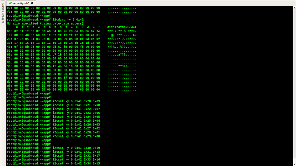
Then we changed it according to your settings, and after that the image lost more outline details.
Could there be some other factor causing this? Thanks!
Hi, our current board is IMX6QP+MAX9286+MAX96705+AP0101AT+AR0143AT , and the kernel version is L4.1.15.
AP0101 is equipped with a flash and uses the firmware provided by the supplier. The video format is: YUV422 8bit/LSB. It has been confirmed that the video data output by the ISP is normal.
Currently only one camera module is connected for debugging. After applying the patch you provided, the following prompt appears:
root@imx6qp-avm718:/unit_tests# ./mxc_v4l2_tvin.out -ol 0 -ot 0 -ow 960 -oh 540 -d 0 -x 0
In MVC: mxc_v4l_open
device name is Mxc Camera
End of mxc_v4l_open: v2f pix widthxheight 288 x 352
End of mxc_v4l_open: crop_bounds widthxheight 1280 x 720
End of mxc_v4l_open: crop_defrect widthxheight 1280 x 720
End of mxc_v4l_open: crop_current widthxheight 1280 x 720
On Open: Input to ipu size is 1280 x 720
max9286_mipi: sensor number = 1.
mxc_mipi_csi2 21dc000.mipi_csi: mipi_csi2_reset: mipi_lane_bps = 148 Mbps
mxc_mipi_csi2 21dc000.mipi_csi: mipi_csi2_reset: value = 0x42.
max9286_mipi 1-006a: ap0101_initialize: AP0101 was found, index = 1.
max9286_mipi 1-006a: ap0101_initialize:AP0101 is already in Slave (Shutter-Sync) Mode.
In MVC:mxc_v4l_ioctl
In MVC: mxc_v4l_do_ioctl 80685600
case VIDIOC_QUERYCAP
In MVC:mxc_v4l_ioctl
In MVC: mxc_v4l_do_ioctl c0045627
case VIDIOC_S_INPUT
In MVC:mxc_streamoff
In MVC:mxc_v4l_ioctl
In MVC: mxc_v4l_do_ioctl c02c563a
case VIDIOC_CROPCAP
In MVC:mxc_v4l_ioctl
In MVC: mxc_v4l_do_ioctl c0cc5616
case VIDIOC_S_PARM
In mxc_v4l2_s_param
Current capabilities are 0
Current capturemode is 0 change to 0
Current framerate is 30 change to 0
clock_curr=mclk=27000000
g_fmt_cap returns widthxheight of input as 1280 x 720
In MVC:mxc_v4l_ioctl
In MVC: mxc_v4l_do_ioctl c0cc5605
case VIDIOC_S_FMT
In MVC: mxc_v4l2_s_fmt
type=V4L2_BUF_TYPE_VIDEO_CAPTURE
End of mxc_v4l2_s_fmt: v2f pix widthxheight 1280 x 720
End of mxc_v4l2_s_fmt: crop_bounds widthxheight 1280 x 720
End of mxc_v4l2_s_fmt: crop_defrect widthxheight 1280 x 720
End of mxc_v4l2_s_fmt: crop_current widthxheight 1280 x 720
In MVC:mxc_v4l_ioctl
In MVC: mxc_v4l_do_ioctl c0cc5604
case VIDIOC_G_FMT
In MVC: mxc_v4l2_g_fmt type=1
type is V4L2_BUF_TYPE_VIDEO_CAPTURE
End of mxc_v4l2_g_fmt: v2f pix widthxheight 1280 x 720
End of mxc_v4l2_g_fmt: crop_bounds widthxheight 1280 x 720
End of mxc_v4l2_g_fmt: crop_defrect widthxheight 1280 x 720
End of mxc_v4l2_g_fmt: crop_current widthxheight 1280 x 720
g_in_width = 1280, g_in_height = In MVC:mxc_v4l_ioctl
720.
In MVC: mxc_v4l_do_ioctl c0145608
case VIDIOC_REQBUFS
In MVC:mxc_streamoff
MVC: In mxc_free_frame_buf
In MVC:mxc_allocate_frame_buf - size=1843200
fb_fix.id = DISP3 BG - DI1.
It is background screen, only full screen default format was supported.
fb: smem_start = 0x73500000, smemIn MVC:mxc_v4l_ioctl
_len = 0xbdd800.
fb: frame buffIn MVC: mxc_v4l_do_ioctl c0445609
er size = 0x3f4800 bytes.
fb: g case VIDIOC_QUERYBUF
_screen_info.xres = 1920, g_screeIn MVC:mxc_v4l2_buffer_status
n_info.yres = 1080.
fb: g_displIn MVC:mxc_mmap
ay_left = 0.
fb: g_display_top pgoff=0x72d00, start=0x75e00000, end=0x75fc2000
= 0.
fb: g_display_width = 1920In MVC:mxc_v4l_ioctl
.
In MVC: mxc_v4l_do_ioctl c0445609
case VIDIOC_QUERYBUF
In MVC:mxc_v4l2_buffer_status
In MVC:mxc_mmap
pgoff=0x72f00, start=0x75c3e000, end=0x75e00000
In MVC:mxc_v4l_ioctl
In MVC: mxc_v4l_do_ioctl c0445609
case VIDIOC_QUERYBUF
In MVC:mxc_v4l2_buffer_status
In MVC:mxc_mmap
pgoff=0x73100, start=0x75a7c000, end=0x75c3e000
In MVC:mxc_v4l_ioctl
In MVC: mxc_v4l_do_ioctl c0445609
case VIDIOC_QUERYBUF
In MVC:mxc_v4l2_buffer_status
In MVC:mxc_mmap
pgoff=0x73300, start=0x758ba000, end=0x75a7c000
In MVC:mxc_v4l_ioctl
In MVC: mxc_v4l_do_ioctl c044560f
case VIDIOC_QBUF
In MVC:mxc_v4l_ioctl
In MVC: mxc_v4l_do_ioctl c044560f
case VIDIOC_QBUF
In MVC:mxc_v4l_ioctl
In MVC: mxc_v4l_do_ioctl c044560f
case VIDIOC_QBUF
In MVC:mxc_v4l_ioctl
In MVC: mxc_v4l_do_ioctl c044560f
case VIDIOC_QBUF
In MVC:mxc_v4l_ioctl
In MVC: mxc_v4l_do_ioctl 40045612
case VIDIOC_STREAMON
In MVC:mxc_streamon
IPU:In csi_enc_enabling_tasks
In csi_enc_setup
start time = 1540834851 s, 23859 In MVC:mxc_v4l_ioctl
us
In MVC: mxc_v4l_do_ioctl c0445611
case VIDIOC_DQBUF
In MVC:mxc_v4l_dqueue
ERROR: v4l2 capture: mxc_v4l_dqueue timeout enc_counter 0
VIDIOC_DQBUF failed.
In MVC:mxc_v4l_ioctl
In MVC: mxc_v4l_do_ioctl 40045613
case VIDIOC_STREAMOFF
In MVC:mxc_streamoff
CSI_MEM0:fffffc0,CIS_MEM1:10ffffc1,CSI_MEM2:11ffffc2,CSI_MEM3:12ffffc3,CSI_PRP_ENC_MEM:13ffffd4,CSI_PRP_VF_MEM:14ffffd5
channel:fffffc0
In MVC:mxc_free_frames
In MVC:mxc_v4l_close
In MVC:mxc_streamoff
mxc_v4l_close: release resource
MVC: In mxc_free_frame_buf
In MVC:mxc_free_frames
It seems that the video data is not obtained. I measured the output of MAX9286 mipi, where the mipi clk is 72MHz, and the waveform on the data pin is as follows;
I considered the problem of the data pins of AP0101 and MAX96705 being misaligned or reversed, but from other people's previous experience, if the data pins are misaligned, the video can be seen, but the video picture is abnormal, and VIDIOC_DQBUF failed will not appear;
Could you please provide some debugging tips? Thanks!
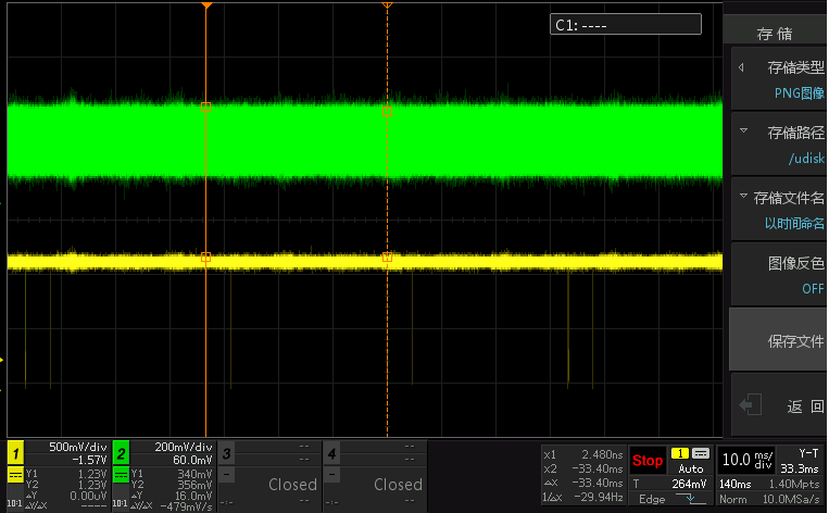
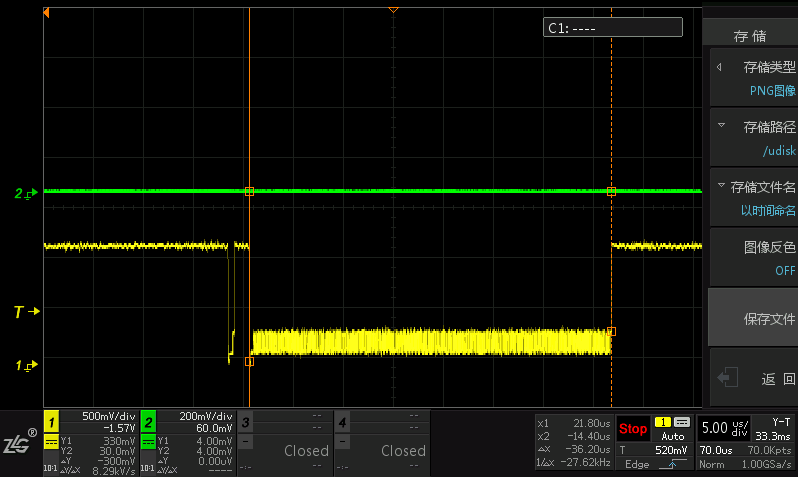
I want to compress four cameras into one 720p video in up, down, left, and right format for storage. How can I integrate the four videos? Do you have any suggestions?
ferhatolgun Hello, have you solved your problem? I am facing the same problem as yours. If you have solved it, could you let me know? Thank you!
Our image was called out in version 3.0.35.
Hi, I reversed the polarity of VS, and then added the code you provided, and now the picture appears, thank you!
Thank you very much for your reply. Bit 19 is 1 and it is ok now. The CSI0_SENS_DATA_FORMAT configuration of CSI data format YUYV and UYUV did not work. Is this modification correct? What causes this problem?
Hi Pengtao,
AP0101 needs to be set to Frame Sync mode instead of the default Free Run mode. In Free Run mode, you will see your phenomenon: a single camera is OK, but multiple cameras are not.
If your camera settings are in the flash ROM, then these settings need to be modified according to the driver.
This should be the high and low data lines from the camera to the MAX96705 are reversed. They can be reversed when setting 96705 (italic part):
#ifdef MAX96705
//Invert VSYNC
max9271_write_reg(0, 0x40, 0x2F);
msleep(2);
max9271_write_reg(0, 0x08, 0x81);
msleep(2);
max9271_write_reg(0, 0x97, 0x5F);
max9271_write_reg(0, 0x20, 0x09);
max9271_write_reg(0, 0x21, 0x08);
max9271_write_reg(0, 0x22, 0x07);
max9271_write_reg(0, 0x23, 0x06);
max9271_write_reg(0, 0x24, 0x05);
max9271_write_reg(0, 0x25, 0x04);
max9271_write_reg(0, 0x26, 0x03);
max9271_write_reg(0, 0x27, 0x02);
max9271_write_reg(0, 0x28, 0x01);
max9271_write_reg(0, 0x29, 0x00);
max9271_write_reg(0, 0x30, 0x19);
max9271_write_reg(0, 0x31, 0x18);
max9271_write_reg(0, 0x32, 0x17);
max9271_write_reg(0, 0x33, 0x16);
max9271_write_reg(0, 0x34, 0x15);
max9271_write_reg(0, 0x35, 0x14);
max9271_write_reg(0, 0x36, 0x13);
max9271_write_reg(0, 0x37, 0x12);
max9271_write_reg(0, 0x38, 0x11);
max9271_write_reg(0, 0x39, 0x10);
#else
Hello, the picture is out now, but the picture is abnormal. The whole picture is green, and the light part is pink. I guess it is because the sensor output is YUYV. In the application mxc_v4l2_tvin.c, I converted the captured data into UYVY and displayed it. The picture color is normal. It is verified that this problem is caused by the sensor output format being YUYV.
Since converting data to UYVY in the application will occupy system resources, make the following changes in the driver and in max9286_mipi.c:
- max9286_data[0].pix.pixelformat = V4L2_PIX_FMT_UYVY;
+ max9286_data[0].pix.pixelformat = V4L2_PIX_FMT_YUYV;
- if(sensor->pix.pixelformat == V4L2_PIX_FMT_UYVY){
+ if(sensor->pix.pixelformat == V4L2_PIX_FMT_YUYV){
for(i = 0; i < MAX_SENSOR_NUM;i++)
mipi_csi2_set_datatype(mipi_csi2_info,i,MIPI_DT_YUV422);
}
Then, execute the following command:
./mxc_v4l2_tvin.out -ol 0 -ot 0 -ow 960 -oh 540 -d 1 -x 0 -if YUYV
Track and check that the CSI_SENS_CONF register value is 0x900, which means that SENS_DATA_FORMAT has been successfully configured to YUYV;
However, the picture output through HDMI is still abnormal, and it is exactly the same as the picture before the modification, which makes it feel like the modification has not taken effect;
Is there any problem with the above modification method? Is there any other place that needs to be modified synchronously? Thank you!
Hello! We are currently adjusting a camera with IMX225+FH8536+MAX96705, platform: IMX6+MAX9286, Kernel version 3.14.52. The basic outline of the video is normal, but the color is not normal, as shown in the figure
In order to verify whether there is a problem with the front-end ISP output, we did an experiment. We disconnected the ISP from the MAX96705, connected the ISP output to a decoder (TW8836), and then debugged 8836. We found that the image can be output normally, that is, there is no problem with the data output by the ISP, and the output format is YVYU.
So I would like to ask, can max96705 convert YVYU data into UYVY format and then pass it to MAX9286? Or how should the display part be processed on the imx6 end?
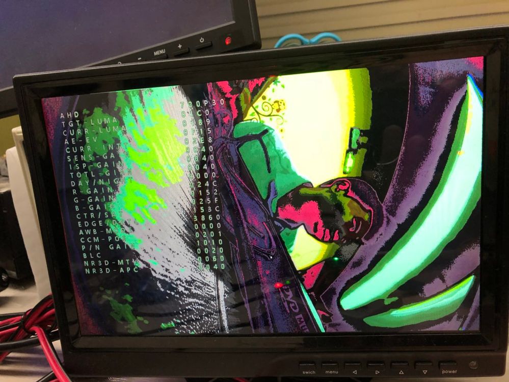
Hi Qiang Li:
I debugged the situation on the L3.14.52_GA1.1.0 version:
1. Onsemi AR0143+AP0101+MAX9 6705+Max9286+Imx6D single channel display is normal.
2. Onsemi AR0143+AP0101+MAX9 6705+Max9286+Imx6D two-way display effect is as shown in the figure:
The camera on the right shows why this is the case, and there are four identical images, all with a green tint.
What is the problem?
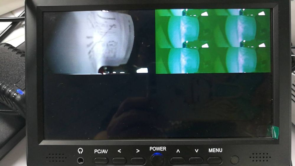
Hello Qiang Li ,
Thanks for your help. The problem has been solved with the solution you provided! The system instability mentioned above is caused by other reasons and has nothing to do with this solution!
Dear Qiang,
I am using the s32v-evb development board to debug MAX9286 + Onsemi AR0140 + AP0101 + MAX9271. Do you have any relevant debugging documents or reference code that you can provide me with?
Thanks a lot.
Currently, the MAX96705 is set up to sample the camera image using 10 data lines. If only 8 lines are connected, the high 2 bits of the image will be lost after inversion, which is basically unacceptable. You can ask Maxim how to handle the 8-line method.
Let's see if your input is:
Raw data input or YUV input, if it is raw CMOS sensor input, it should be 12bit. Bit loss will cause problems. If it is 8-bit YUV input (BT656), it depends on whether you have the right bits, 0~7 or 2~9... Serdis usually does a transmission, what is input is what is output~
Hello, can I ask you a question: 1. I see that FH8536 seems to have only analog output, how did you connect it to 96705; 2. If IMX225+FH8536 is used, how do you synchronize the images of the four lens modules? Looking forward to your reply, thank you!
You can measure the lock pin of MAX9286. It should be high all the time to ensure the stable output of MIPI data. If the camera and MAX9286 are not set up properly, the high level cannot be maintained all the time, and the data will be incomplete.
From the test results of AP0101, the MAX9286 needs to be set to manual mode, and the register 0x08 needs to be adjusted according to the camera's frame rate setting:
#ifdef SENSOR_AP0101
//Manual Mode
max9286_write_reg(0x01, 0x00);
max9286_write_reg(0x63, 0x00);
max9286_write_reg(0x64, 0x00);
max9286_write_reg(0x06, 0x00);
max9286_write_reg(0x07, 0x00);
max9286_write_reg(0x08, 0x26);
#endif
hi Qiang li:
Because the products we developed with BYD include tw6865 + max9286. I have already adjusted tw6865 on 3.0.35, but it is more difficult to adjust 9286 on 3.0.35, so I hope to get your help.
I think the first step should be to enable the 4 virtual channels of imx6 to collect data at the same time. The second step is to adjust the device. At present, max9286 can sometimes detect the device AP0101, but sometimes it cannot detect it. I don’t know why. I suspect that there is a problem with enabling the 4 virtual channels. I transplanted it according to the patch 3.10.53 you released. I hope to get your help.
Hi Qiang Li !
How many 720P 60fps camera inputs can imx8 support? (All IMX8 included)
On the MAX9286 side, you can try to modify register 0x08
max9286_write_reg(0x08, 0x26);
Change to
max9286_write_reg(0x08, 0x2C);
It is best to refer to the settings in the Driver for the Flash settings in your Camera module. The frame rate under FrameSync mode should be determined by the MAX9286. So in theory, it should not happen that the MAX9286 sends FrameSync to the camera at 30fps while the camera sends images at 25fps.
Hi, our lens uses MAX96705+AP0101+AR0143AT, AP0101 is connected with a flash, ISP output is YUV422/8bit/LSB, and VIDIOC_DQBUF failed is displayed. After reading other people's questions, it seems that VIDIOC_DQBUF failed will not appear if it is a data misalignment problem.
hello yu : 能否将l3.0.35的补丁给我一份,[email protected]。感激不尽
According to the MIPI specification, the YUV422 transmitted by MIPI CSI2 should be in UYVY format, but you are transmitting YUYV, so you cannot use a unified setting to process it.
In mxc_v4l2_tvin, the settings of g_in_fmt (g_g2d_fmt) will be set in the Driver by default, and will also be used when rendering. According to your situation, the Driver should use all UYVY settings, and then when rendering, just change g_in_fmt (g_g2d_fmt) to YUYV.
The lock pin of MAX9286 cannot maintain a high level, which means it cannot completely lock the camera signal. Then the data on MIPI CSI2 must be problematic. This has nothing to do with the iMX6.
In addition, my environment is as follows:
- OV10635 sensor
- MAX96705 Serializer
- MAX9286 Deserializer
- kernel 4.1.15
- patch L3.14.52_GA1.1.0_MAX9286_Surroundview_Patch_2016-07-26.zip
The image can be displayed, but the color is wrong.
Hi, my previous statement was wrong. The real reason is that the CSI2IPU gasket output format is configured as YUYV. The problem is solved after setting the YUV422_8BIT_FM of the CSI2IPU_SW_RST register to UYVY. Thank you!
Hello Qiang_FSL , there is also a color problem!
I saw your email and compared it with the original code. I found that the ov10635_setting in the email is exactly the same as the setting in the original code.
There is also the file MAX9286_OV10635_1280x800_Quad_FSIN_MOD.C. I don’t know if it is useful to me. How can I modify the original code?
Hi. Qiang Li
When we connect 4 720p@60pfs cameras, what is the delay from camera connection to display on the screen? Do you have this performance indicator?
When we access 8-way For a 720p@60pfs camera, what is the latency from camera access to screen display? Do you have this performance indicator?
Thanks for your reply. We are now running normally with 0143+0101+96705. The synchronization of 0143 is indeed controlled by the trigger in of the sensor, but IMX225 does not seem to have a trigger pin. The datasheet describes that slave mode requires VS and HS. In addition, I see that the FH8536 ISP only has analog output, and 96705 does not seem to be able to connect to analog input. I don't know how the IMX225+FH8536+MAX96705 solution solves these two problems.
The photosensitive sensor I use here is AP0143; the sensor has been frame synced, because in the previous mode, multiple sensors cannot produce images;
Now when I capture 320 lines and connect three sensors, there will be no scrolling, but there will be horizontal bars and jitter.
It depends on what camera sensor you use. If you buy a ready-made module, it usually comes with flash, and its working mode is set in the flash ROM. Even if the Frame Sync mode is set on the MAX9286, the camera mode cannot be changed.
In addition, for some camera sensors (such as AP0101+AR0130), the time from HSYNC to VSYNC of the last line is less than 255 pixel clocks, which may also cause problems. In this case, the IPU CSI needs to capture fewer lines of data. For example, for an input of 720 lines, the IPU CSI only captures 712 lines.
I also need the patch for version L3.0.35_4.1.0, thank you
Qiang li:
The patches applied in bsp 3.10.53 are as follows:
static int mipi_csi2_probe(struct platform_device *pdev)
{
. . . . . . . . . .
ret = of_property_read_u32(np, "lanes", &(gmipi_csi2->lanes));
if (ret) {
dev_err(&pdev->dev, "lanes missing or invalid\n");
goto err;
}
if (gmipi_csi2->lanes > 4) {
dev_err(&pdev->dev, "invalid lanes for mipi csi2!\n");
ret = -EINVAL;
goto err;
}
for_each_child_of_node(np, child) {
struct mipi_csi2_chan *chan;
if (!of_device_is_available(child))
continue;
ret = of_property_read_u32(child, "v_channel", &v_channel);
if (ret) {
dev_err(&pdev->dev, "v_channel missing\n");
goto err;
}
if (v_channel > 3) {
dev_err(&pdev->dev, "v_channel invalid\n");
ret = -EINVAL;
goto err;
}
chan = &(gmipi_csi2->mipi_chan[v_channel]);
ret = of_property_read_u32(child, "ipu_id", &(gmipi_csi2->mipi_chan[v_channel].ipu_id));
if (ret) {
dev_err(&pdev->dev, "ipu_id missing or invalid\n");
goto err;
}
ret = of_property_read_u32(child, "csi_id", &(gmipi_csi2->mipi_chan[v_channel].csi_id));
if (ret) {
dev_err(&pdev->dev, "csi_id missing or invalid\n");
goto err;
}
if ((gmipi_csi2->mipi_chan[v_channel].ipu_id < 0) ||
(gmipi_csi2->mipi_chan[v_channel].ipu_id > 1) ||
(gmipi_csi2->mipi_chan[v_channel].csi_id > 1)) {
dev_err(&pdev->dev, "invalid param for mipi csi2!\n");
ret = -EINVAL;
goto err;
。。。。。。。。。。。。
This is how I handled this part in 3.0.35. Please help me check if there is any problem.
static int mipi_csi2_probe(struct platform_device *pdev)
{
struct mipi_csi2_platform_data *plat_data = pdev->dev.platform_data;
struct resource *res;
u32 mipi_csi2_dphy_ver;
struct mipi_csi2_chan *chan;
int ret , v_channel;
printk("mipi_csi2 probe start !!!!!!!!!!!!!!!!!!!!!\n");
gmipi_csi2 = kmalloc(sizeof(struct mipi_csi2_info), GFP_KERNEL);
if (!gmipi_csi2) {
ret = -ENOMEM;
goto alloc_failed;
}
printk("v_channel is %d !!!!!!!!!!!!!!!!1111\n",v_channel);
/* initialize mutex */
mutex_init(&gmipi_csi2->mutex_lock);
chan = &(gmipi_csi2->mipi_chan[v_channel]);
/* get mipi csi2 informaiton */
gmipi_csi2->pdev = pdev;
gmipi_csi2->mipi_en = false;
//gmipi_csi2->ipu_id = plat_data->ipu_id;
//gmipi_csi2->csi_id = plat_data->csi_id;
//gmipi_csi2->v_channel = plat_data->v_channel;
gmipi_csi2->lanes = plat_data->lanes;
printk("plat_data lanes is %d !!!!!!!!!!!!!!!\n", plat_data->lanes);
v_channel = plat_data->v_channel;
gmipi_csi2->mipi_chan[v_channel].ipu_id= plat_data->ipu_id;
gmipi_csi2->mipi_chan[v_channel].csi_id= plat_data->csi_id;
if ((gmipi_csi2->mipi_chan[v_channel].ipu_id < 0) ||
(gmipi_csi2->mipi_chan[v_channel].ipu_id > 1) ||
(gmipi_csi2->mipi_chan[v_channel].csi_id > 1)) {
dev_err(&pdev->dev, "invalid param for mipi csi2!\n");
ret = -EINVAL;
}
. . . . . . .
The platform data is as follows:
static struct mipi_csi2_platform_data mipi_csi2_pdata = {
.ipu_id = 0, //0 // modify by lee
.csi_id = 0,
.v_channel = 0,
.lanes = 4,
.dphy_clk = "mipi_pllref_clk",
.pixel_clk = "emi_clk",
};
Is this operation OK? Thank you. I have been dealing with max9286 on 3.0.35 for a long time. There has been no progress. I hope to get your support.
Thanks for your reply,
Our application scenario is like this: the 4-way spliced display screen is encoded and stored, so it is equivalent to only encoding one 720P. Since it is not a direct encoding of the original image, it is impossible to output the UYVY image into NV12 for encoding through the camera driver. Our splicing is achieved through the GPU, and the image sent to the encoder is RGBA32, so the color space conversion is required before encoding, and then the image is abnormal.
In fact, we also tested the color conversion of a single-channel 720×480 image, that is, first reduce the 720P image to 720×480 through the GPU and then transcode and record with this resolution image, which will also cause input image abnormality. If we transcode 720×480 (RGBA32 -> NV12 or UYVY -> NV12), only one channel will be abnormal. If the transcoding is 1280×720, except for the first channel, the other three channels are all abnormal.
I checked the underlying driver and found that the data flow is CSI--> SMFC--> IDMAC--> MEM. I tracked the IDMAC channel usage and the default is
CSI_MEM0 = _MAKE_CHAN(15, NO_DMA, NO_DMA, NO_DMA, 0).
CSI_MEM1 = _MAKE_CHAN(16, NO_DMA, NO_DMA, NO_DMA, 1),
CSI_MEM2 = _MAKE_CHAN(17, NO_DMA, NO_DMA, NO_DMA, 2),
CSI_MEM3 = _MAKE_CHAN(18, NO_DMA, NO_DMA, NO_DMA, 3), The
problem at 720×480 is CSI_MEM1 = _MAKE_CHAN(16, NO_DMA, NO_DMA, NO_DMA, 1). If the above channel control is modified as follows
CSI_MEM0 = _MAKE_CHAN(15, NO_DMA, NO_DMA, NO_DMA, 1),
CSI_MEM1 = _MAKE_CHAN(16, NO_DMA, NO_DMA, NO_DMA, 0),
CSI_MEM2 = _MAKE_CHAN(17, NO_DMA, NO_DMA, NO_DMA, 2),
CSI_MEM3 = _MAKE_CHAN(18, NO_DMA, NO_DMA, NO_DMA, 3), Then the problematic
channel becomes CSI_MEM0 = _MAKE_CHAN(15, NO_DMA, NO_DMA, NO_DMA, 1). From this perspective, it seems that the driver has a conflict in managing the underlying resources. Or the hardware itself does not support this usage. Can you help confirm the root cause of the problem and do you have any suggestions?
zhang hongliang :
Hello. My sensor is the same as yours, ov10640+ ov490 ISP + max96705. Could you please send me a copy of your debugged code? Or what parameters or registers should I change in the official code?
Thanks
The standard 720P60 pixel clock is 74.25MHz. If it is UYVY For a 16bpp camera, the bandwidth of a single camera is 74.25M*16. = 1.188Gbps
The maximum bandwidth of MIPI CSI2 of iMX8 and iMX8X is 6Gbps, and each can support 4 virtual channels, so each MIPI CSI2 port can support 4 720P60 cameras. iMX8 has 2 MIPI CSI2 ports, so it can support 8. iMX8X has only one MIPI CSI2, so it can support 4 channels, but it has an 8-bit parallel CSI, which can also support one 720P camera, which adds up to 5 channels.
Although iMX8M has 2 MIPI CSI2, it does not support multi virtual channel, so it can only support 2 cameras.
HI Liqiang:
Hello!
I use imx6d + max9286 + max96705 to preview three cameras at the same time. When two or three cameras are connected, the preview screen will shake and roll;
It's normal for me to only connect one camera.
Confirmed with Maxim FAE that all cameras are in frame sync mode.
I have been looking for this question for a long time. Please help me