
- Forums
- Product Forums
- General Purpose MicrocontrollersGeneral Purpose Microcontrollers
- i.MX Forumsi.MX Forums
- QorIQ Processing PlatformsQorIQ Processing Platforms
- Identification and SecurityIdentification and Security
- Power ManagementPower Management
- Wireless ConnectivityWireless Connectivity
- RFID / NFCRFID / NFC
- Advanced AnalogAdvanced Analog
- Neural Processing UnitsNeural Processing Units
- MCX Microcontrollers
- S32G
- S32K
- S32V
- MPC5xxx
- Other NXP Products
- S12 / MagniV Microcontrollers
- Powertrain and Electrification Analog Drivers
- Sensors
- Vybrid Processors
- Digital Signal Controllers
- 8-bit Microcontrollers
- ColdFire/68K Microcontrollers and Processors
- PowerQUICC Processors
- OSBDM and TBDML
- S32M
- S32Z/E
-
- Solution Forums
- Software Forums
- MCUXpresso Software and ToolsMCUXpresso Software and Tools
- CodeWarriorCodeWarrior
- MQX Software SolutionsMQX Software Solutions
- Model-Based Design Toolbox (MBDT)Model-Based Design Toolbox (MBDT)
- FreeMASTER
- eIQ Machine Learning Software
- Embedded Software and Tools Clinic
- S32 SDK
- S32 Design Studio
- GUI Guider
- Zephyr Project
- Voice Technology
- Application Software Packs
- Secure Provisioning SDK (SPSDK)
- Processor Expert Software
- Generative AI & LLMs
-
- Topics
- Mobile Robotics - Drones and RoversMobile Robotics - Drones and Rovers
- NXP Training ContentNXP Training Content
- University ProgramsUniversity Programs
- Rapid IoT
- NXP Designs
- SafeAssure-Community
- OSS Security & Maintenance
- Using Our Community
-
- Cloud Lab Forums
-
- Knowledge Bases
- ARM Microcontrollers
- i.MX Processors
- Identification and Security
- Model-Based Design Toolbox (MBDT)
- QorIQ Processing Platforms
- S32 Automotive Processing Platform
- Wireless Connectivity
- CodeWarrior
- MCUXpresso Suite of Software and Tools
- MQX Software Solutions
- RFID / NFC
- Advanced Analog
- Neural Processing Units
-
- NXP Tech Blogs
- Home
- :
- 汎用マイクロコントローラ
- :
- モーター制御とスマートエネルギー
- :
- Re: BLDC_OpenLoop_mpc5744p_Rev. E
BLDC_OpenLoop_mpc5744p_Rev. E
- RSS フィードを購読する
- トピックを新着としてマーク
- トピックを既読としてマーク
- このトピックを現在のユーザーにフロートします
- ブックマーク
- 購読
- ミュート
- 印刷用ページ
- 新着としてマーク
- ブックマーク
- 購読
- ミュート
- RSS フィードを購読する
- ハイライト
- 印刷
- 不適切なコンテンツを報告
Hello
Many Thanks for your support in advance!
I want to test the BLDC_open loop on DevKit-MPC5744P Rev. E and DevKit MotorGD.
Unfortunately, some jumpers and settings are mentioned in the HW and SW setup in Simulink model are not available in Rev. E.
1- Which Jumpers on MPC5744P Rev. E should be adapted?
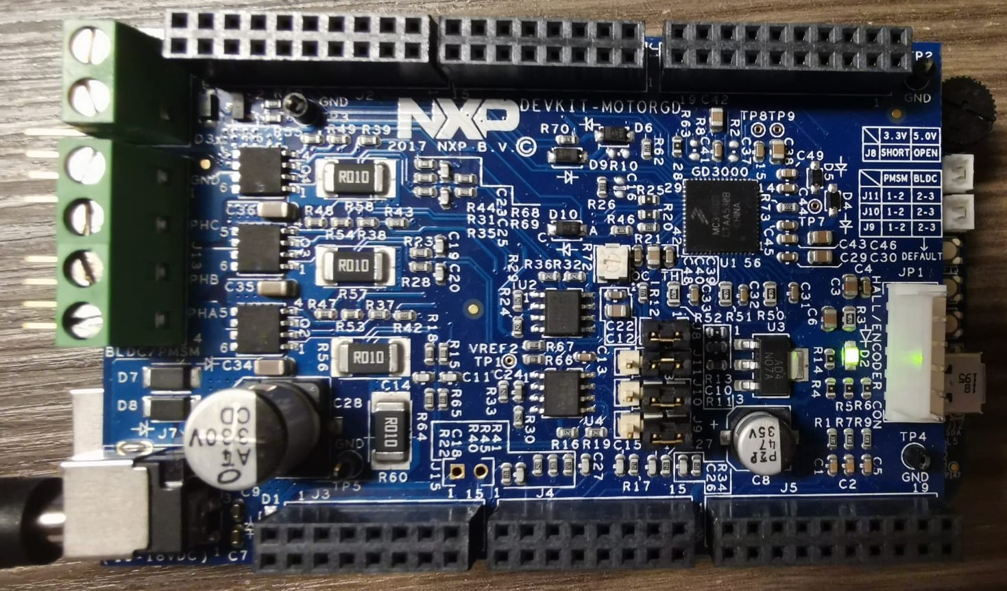
2- Should R70 and R73 be removed from MotorGD? Are there any other changes, which should be considered?
3- Which settings and which blocks should be adapted in Simulink model BLDC_OpenLoop_mpc5744p_RevE.slx ?
In my opinion it makes really sense to go through the steps and update them in HW and SW setup for Rev. E.
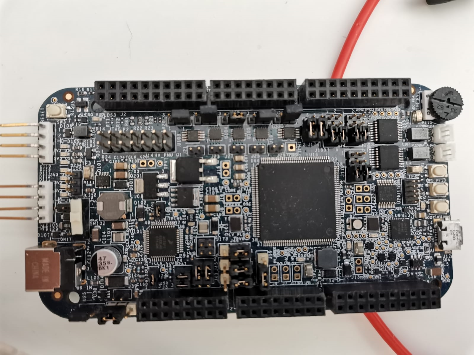
Attached are the pictures of both boards as well as the Simulink file.
I would be very happy to hear from you as soon as possible
解決済! 解決策の投稿を見る。
- 新着としてマーク
- ブックマーク
- 購読
- ミュート
- RSS フィードを購読する
- ハイライト
- 印刷
- 不適切なコンテンツを報告
@eCarMaker Hello,
If you followed all the steps that I told you about, then it is possible that you have a hardware fault (something broken). Try to measure your 12V DC power supply after you connect to the Motor-GD board (maybe it's getting some current protection). If so, measure the power transistors or just replace this board (Motor-GD) with another one.
Best regards,
Adrian
- 新着としてマーク
- ブックマーク
- 購読
- ミュート
- RSS フィードを購読する
- ハイライト
- 印刷
- 不適切なコンテンツを報告
- 新着としてマーク
- ブックマーク
- 購読
- ミュート
- RSS フィードを購読する
- ハイライト
- 印刷
- 不適切なコンテンツを報告
Hello Peter,
Thanks for your quick response.
I've just opend the attached Simulink file. Unfortunately nothing is changed in the model description and the jumber settings which are described on the top level of the simulink model. I still can see the names of some jumbers which are not available anymore in Rev. E e.g. J26, J32 and J38.
In the original post I mentioned three questions or points. Therefore, I am asking you kindly to go through them just to prevent the pingpong.
With best regards
- 新着としてマーク
- ブックマーク
- 購読
- ミュート
- RSS フィードを購読する
- ハイライト
- 印刷
- 不適切なコンテンツを報告
Hello,
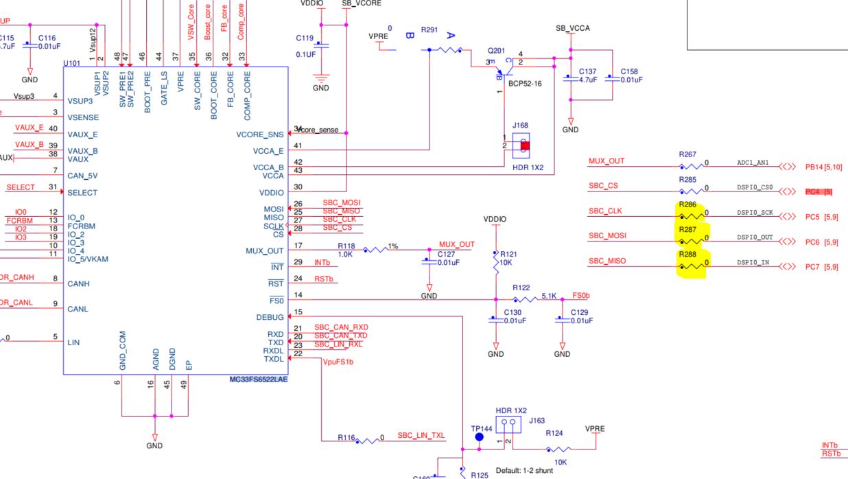
I found that the MPC5744P board revE uses the same SPI instance for an onboard IC (MC33FS6522LAE SBC) and for GD3000 IC. Due to that the SBC CS pin must be set to disable the communication on the SPI interface in order to allow GD3000 to be initialized. I tried that but it didn't work for me.
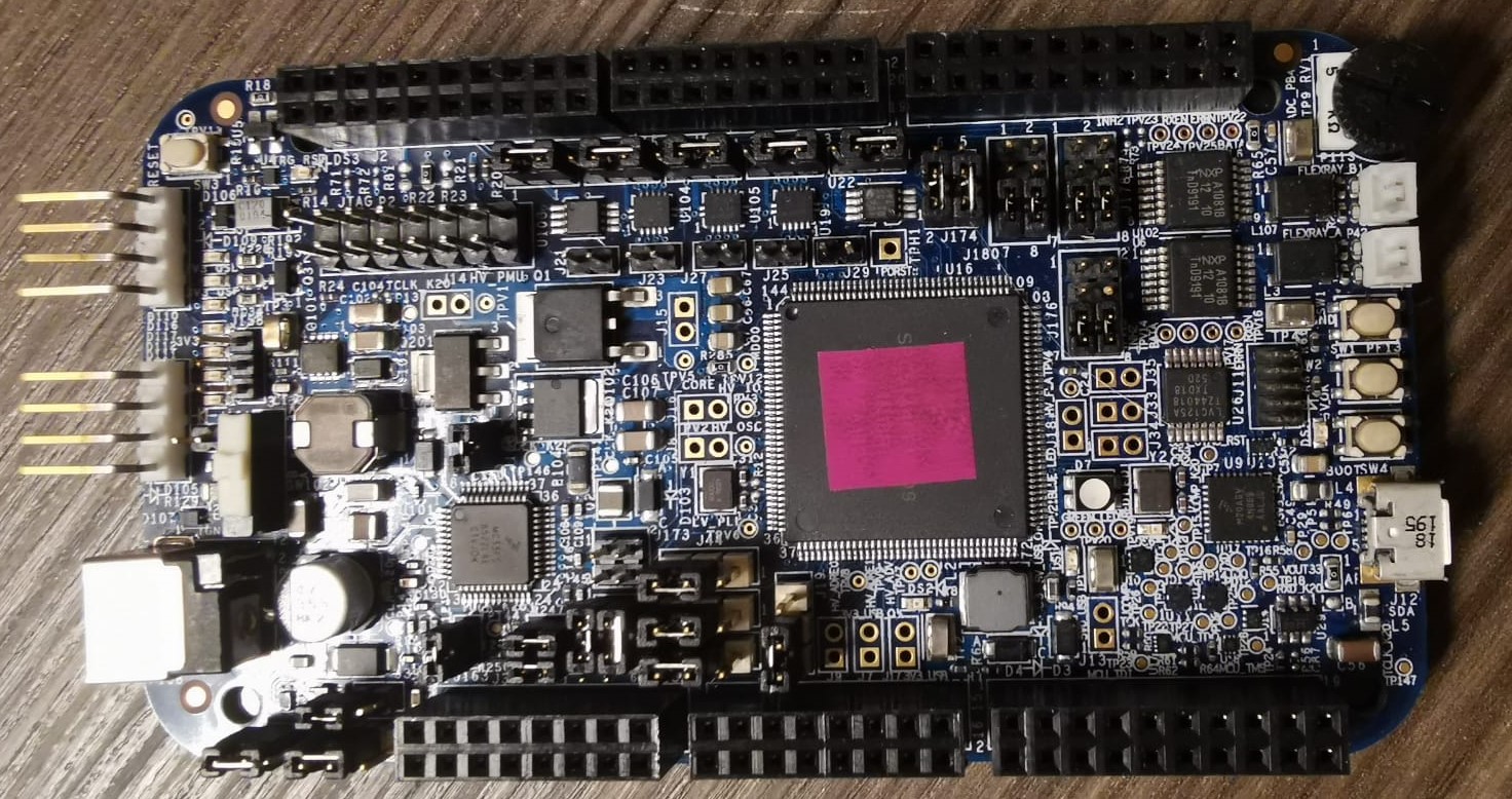
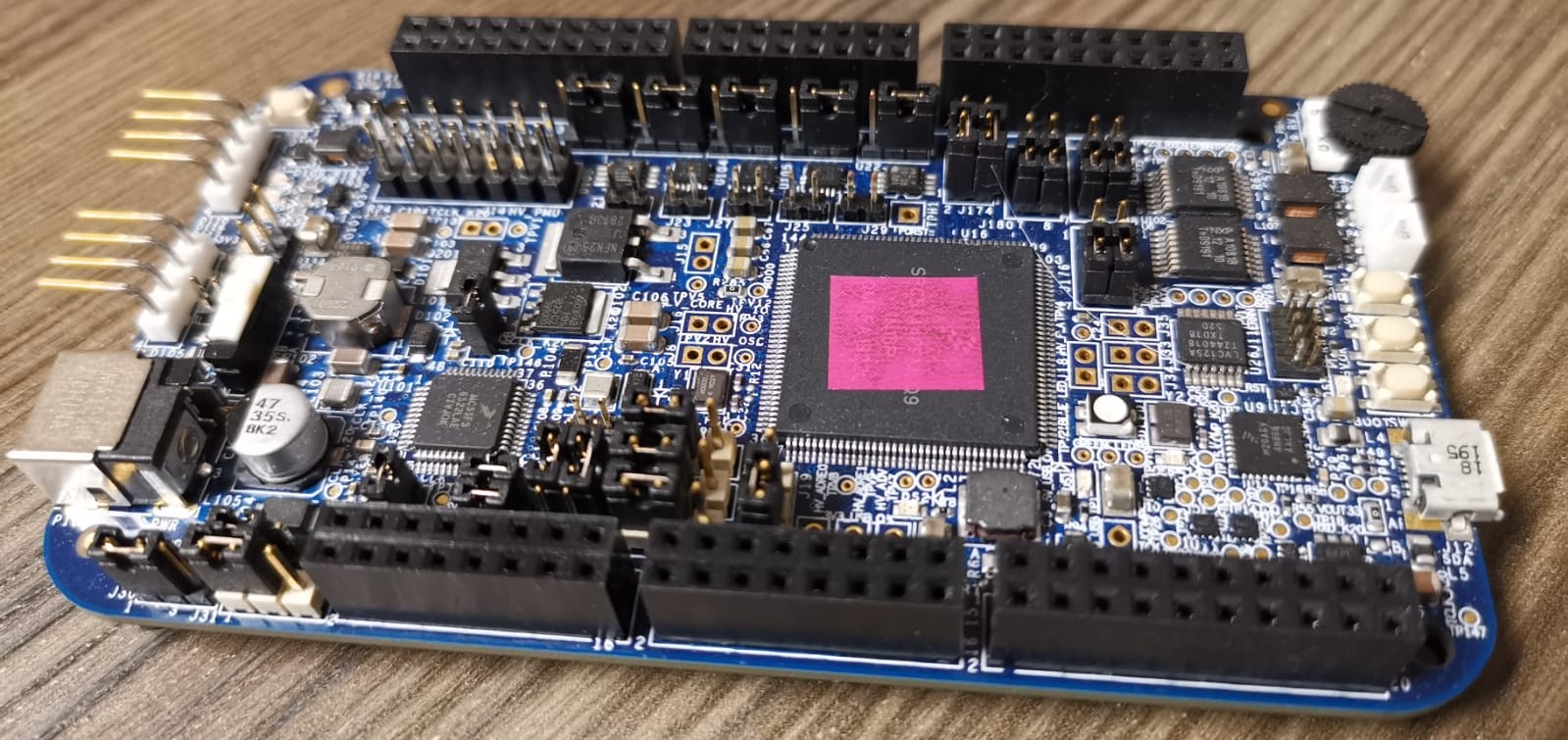
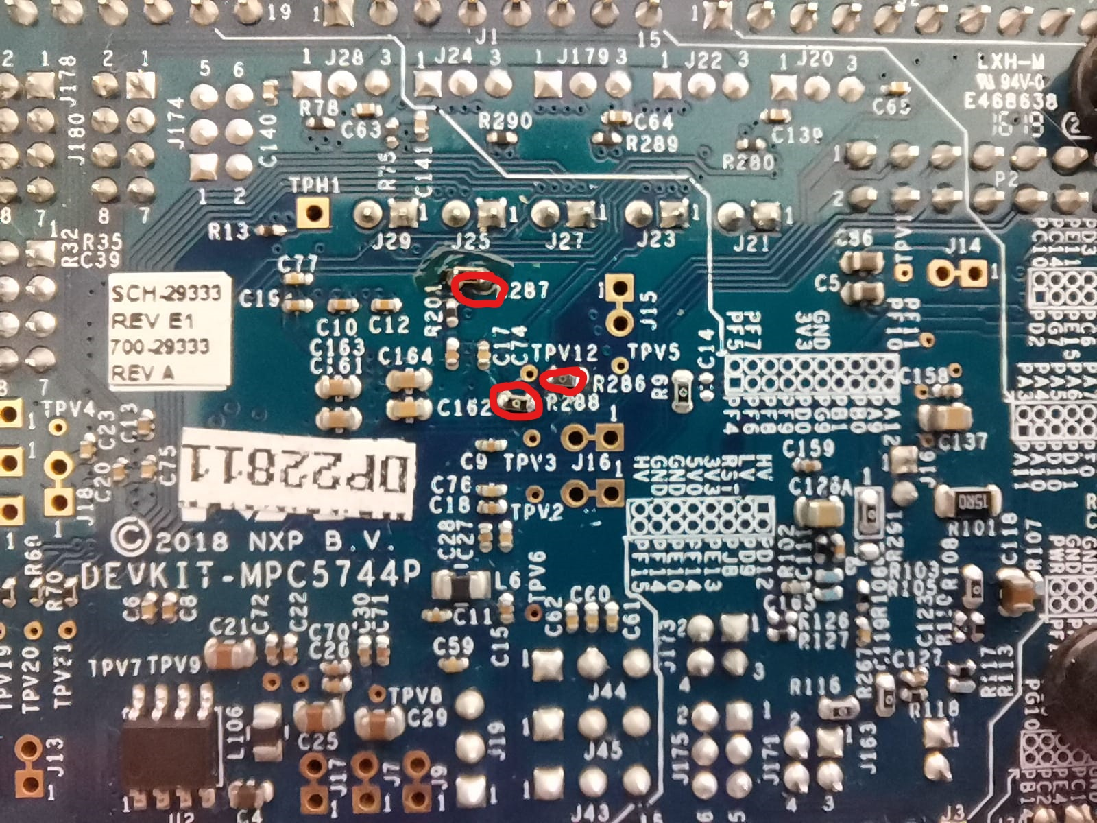
But I found another solution a little more intrusion. On the MPC board, only if you don't need any of the SBC IC functions (CAN, LIN), you have to remove three resistors that connect three of the SPI interface pins to SBC IC. Those resistors are R286, R287, and R288. Please take a look at those pictures. Also in those pictures, you can find how to set jumpers for both boards and the BLDC model.
Please let me know if that solution works for you.
Best regards,
Adrian
- 新着としてマーク
- ブックマーク
- 購読
- ミュート
- RSS フィードを購読する
- ハイライト
- 印刷
- 不適切なコンテンツを報告
Hello Adrian,
Thanks for your answer. I did the following steps,
- I removed the resistances R286, R287 and R288 from MPC5744P board Rev. E.
- The power is provided to the MPC5744P board by SBC power supply (instead of USB connection), according to your jumper settings J43, J44 and J45 in picture MPC5744P_board.
- I used the Simulink file BLDC_ClosedLoop_mpc5744pRevE.slx (which provided in your answer BLDC_ClosedLoopRevE_2021.7z) to program MPC5744p_Rev. E. Everything was running and the mot file was downloaded on the MPC5744P as expected.
- Before I connected the 12 volt to DEVKIT-MotorGD (inverter board) I could communicate with the board using FreeMaster without any problem. I could increase the reference speed for example 500 rpm, as you can see in the picture FreeMaster_SpeedController and FreeMaster_PI SpeedControllerResponse, but the speed error was always zero, which I couldn't understand. Even the Dc-BusCurrent value was strange (-16.45 A) as in picture FreeMaster_BLDC closed Loop, although the 12 volt was not connected to the inverter board.
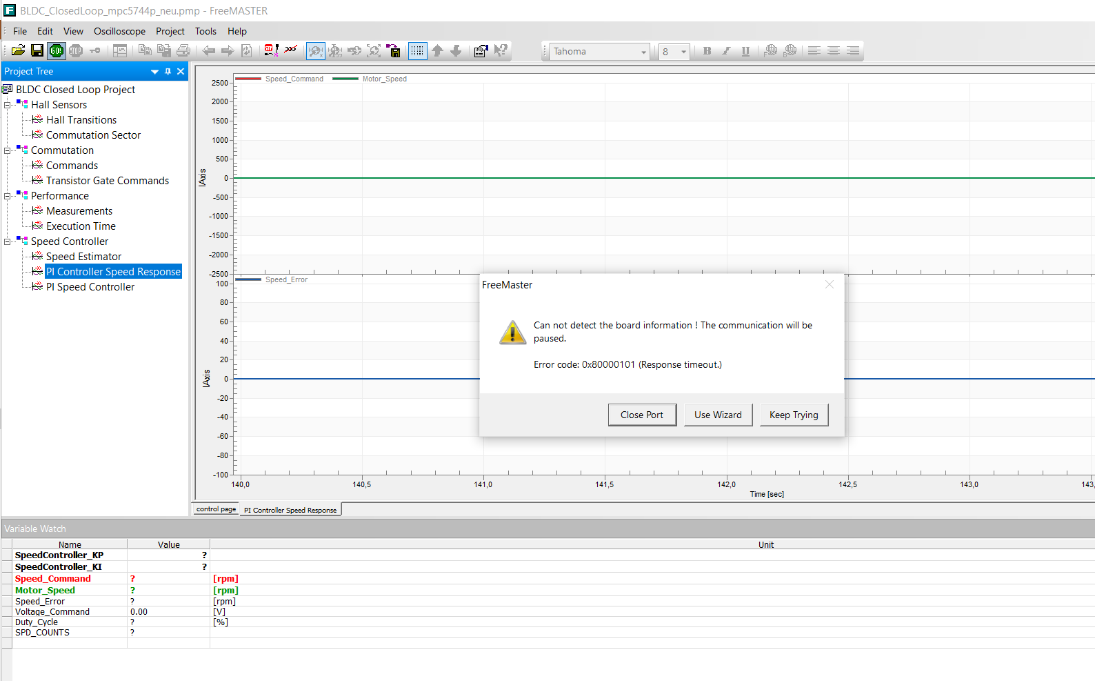
- As 12 volt was provided to the inverter board, it lost the connection with FreeMaster, as in FreeMaster_Connectionwith12Volt. Unfortunately it was no success even after many resets.
- To make sure what caused the FreeMaster problem in step 5. I used another simulink file but for VF control (an open loop) VF_control_MP574xP_01.slx. Everything was ok and the FreeMaster could communicate with the board without any problem, even when the 12 volt was connected to the inverter board. That means in my opinion the problem was related to the provided simulink file BLDC_ClosedLoop_mpc5744pRevE.slx
For completeness I will provide all files which I used for this project and pictures related to my HW-setup
- For VF Open loop see VF Control_mpc5744p.rar
- For Closed Loop Rev. E, see BLDC_ClosedLoop_mpc5744p.rar
- For the HW, see My HW Setup.rar
Q1: Could you please help me to understand why we still face these FreeMaster problems with this setup and why we got these values from Dc-BusCurrent and speed controller output
Q2: Could you please provide pictures about the actual motor speed and PI speed controller output, once you change the reference speed.
I am looking forward to hearing from you soon
With Best Regards
- 新着としてマーク
- ブックマーク
- 購読
- ミュート
- RSS フィードを購読する
- ハイライト
- 印刷
- 不適切なコンテンツを報告
@eCarMaker Hello,
In order to start this motor control demo app, you have to turn R72 (trimmer resistor placed on Motor-GD devkit) in counter-clockwise direction until you hit the edge, but please be gentle to not damage it.
Whenever you flash MPC5744P, please disconnect the FreeMaster app project.
After the flashing process, be sure that 12V power DC it is connected to the Motor-GD board and wait for the RGB led (placed on the MPC5744P board) to turn the green light on. At this time you can connect the FreeMaster app project and if you push the SW1 or SW2 button, the motor should spin. Please keep in mind that the motor will not start to spin until you press one of two buttons or until you set the speed to a value higher than 500rpm and set the "START" variable in FreeMaster to 1 (if the "START" variable is not editable, double click on that variable then see the picture below to make it user-editable).
And another very important thing: whenever you press the "reset" button (placed on MPC5744P board), the FreeMaster should be disconnected. If is not disconnected, the bootloader of the MPC mcu will be stuck and will not run the application that you flashed via OpenSDA. And after each press of this reset button, you have to wait more than 5 sec. . You can wait until the RGB led is turned green.
You got those value because the Motor-GD it was not powered and the value of the currents and the voltages are given by the Motor-GD board and read by the MPC mcu.
I hope this information will help you to go further.
Let me know if that works for you.
Best regards,
Adrian
- 新着としてマーク
- ブックマーク
- 購読
- ミュート
- RSS フィードを購読する
- ハイライト
- 印刷
- 不適切なコンテンツを報告
Hello,
Thanks for your quick response.
- If 12V power DC isn't connected to the Motor-GD the FreeMaster can be connected to the MPC5744P and I could see the reaction of the SW. The speed can be increased and decreased and the duty cycle is also changing.
- If I repeat the same steps with same described order but with 12V power DC, the freeMaster can't connect the MPC5744P and I got an error message, see the attached picture.
Unfortunately till now there is no success .....
- 新着としてマーク
- ブックマーク
- 購読
- ミュート
- RSS フィードを購読する
- ハイライト
- 印刷
- 不適切なコンテンツを報告
@eCarMaker Hello,
If you followed all the steps that I told you about, then it is possible that you have a hardware fault (something broken). Try to measure your 12V DC power supply after you connect to the Motor-GD board (maybe it's getting some current protection). If so, measure the power transistors or just replace this board (Motor-GD) with another one.
Best regards,
Adrian
- 新着としてマーク
- ブックマーク
- 購読
- ミュート
- RSS フィードを購読する
- ハイライト
- 印刷
- 不適切なコンテンツを報告
Thanks Adrian.
You were right. One PWM port on Motor-GD board was broken. It works after replacing it.
Thanks a lot for your support!
Best regards
- 新着としてマーク
- ブックマーク
- 購読
- ミュート
- RSS フィードを購読する
- ハイライト
- 印刷
- 不適切なコンテンツを報告
Hello,
I was talking to responsible engineer and he promised to post here.
Unfortunately I was 2 weeks away due to sickness and I see he did not posted anything here.
I will ping him this week to see what is the status.
Best regards,
Peter
- 新着としてマーク
- ブックマーク
- 購読
- ミュート
- RSS フィードを購読する
- ハイライト
- 印刷
- 不適切なコンテンツを報告
Hello Peter,
Hello Everyone, I posted my question here on 9th of March 2021. Unfortunately, more than 2 months are over and I haven't got the proper answer till now 16th of May 2021. In meanwhile I could rotate the motor using DevKit-MPC5744P Rev. E and another power stage kit from STM (X-NUCLEO-IHM07M1). But we still preffer using DevKit MotorGD from NXP in our project. Please let me know if I can expect any answer from your side in next 2 weeks. Otherwise I will consider ST power stage in our project.
Many thanks in adavance !
- 新着としてマーク
- ブックマーク
- 購読
- ミュート
- RSS フィードを購読する
- ハイライト
- 印刷
- 不適切なコンテンツを報告
Hello Peter,
is there any update from your side?
Many thanks!
- 新着としてマーク
- ブックマーク
- 購読
- ミュート
- RSS フィードを購読する
- ハイライト
- 印刷
- 不適切なコンテンツを報告
Hello,
I am trying to get in touch with responsible engineer.
Once I have any news I will post here,
best regards,
Peter
- 新着としてマーク
- ブックマーク
- 購読
- ミュート
- RSS フィードを購読する
- ハイライト
- 印刷
- 不適切なコンテンツを報告
Hello,
I was talking with motor control team and they have same issue as you.
It looks like designer design new revision of control board which is not pin to pin compatible with inverter.
The solution is to use cable connection, set wont wort without them.
Motor control expert will prepare some material where is described step by step procedure during next week.
Best regards,
Peter