
- Forums
- Product Forums
- General Purpose MicrocontrollersGeneral Purpose Microcontrollers
- i.MX Forumsi.MX Forums
- QorIQ Processing PlatformsQorIQ Processing Platforms
- Identification and SecurityIdentification and Security
- Power ManagementPower Management
- Wireless ConnectivityWireless Connectivity
- RFID / NFCRFID / NFC
- Advanced AnalogAdvanced Analog
- Neural Processing UnitsNeural Processing Units
- MCX Microcontrollers
- S32G
- S32K
- S32V
- MPC5xxx
- Other NXP Products
- S12 / MagniV Microcontrollers
- Powertrain and Electrification Analog Drivers
- Sensors
- Vybrid Processors
- Digital Signal Controllers
- 8-bit Microcontrollers
- ColdFire/68K Microcontrollers and Processors
- PowerQUICC Processors
- OSBDM and TBDML
- S32M
- S32Z/E
-
- Solution Forums
- Software Forums
- MCUXpresso Software and ToolsMCUXpresso Software and Tools
- CodeWarriorCodeWarrior
- MQX Software SolutionsMQX Software Solutions
- Model-Based Design Toolbox (MBDT)Model-Based Design Toolbox (MBDT)
- FreeMASTER
- eIQ Machine Learning Software
- Embedded Software and Tools Clinic
- S32 SDK
- S32 Design Studio
- GUI Guider
- Zephyr Project
- Voice Technology
- Application Software Packs
- Secure Provisioning SDK (SPSDK)
- Processor Expert Software
- Generative AI & LLMs
-
- Topics
- Mobile Robotics - Drones and RoversMobile Robotics - Drones and Rovers
- NXP Training ContentNXP Training Content
- University ProgramsUniversity Programs
- Rapid IoT
- NXP Designs
- SafeAssure-Community
- OSS Security & Maintenance
- Using Our Community
-
- Cloud Lab Forums
-
- Knowledge Bases
- ARM Microcontrollers
- i.MX Processors
- Identification and Security
- Model-Based Design Toolbox (MBDT)
- QorIQ Processing Platforms
- S32 Automotive Processing Platform
- Wireless Connectivity
- CodeWarrior
- MCUXpresso Suite of Software and Tools
- MQX Software Solutions
- RFID / NFC
- Advanced Analog
- Neural Processing Units
-
- NXP Tech Blogs
- Home
- :
- モデルベース・デザイン・ツールボックス(MBDT)
- :
- モデルベース・デザイン・ツールボックス(MBDT)
- :
- Re: MBDT Toolbox SPI transfer does not correctly issue multi-byte transfers (bug report, critical)
MBDT Toolbox SPI transfer does not correctly issue multi-byte transfers (bug report, critical)
- RSS フィードを購読する
- トピックを新着としてマーク
- トピックを既読としてマーク
- このトピックを現在のユーザーにフロートします
- ブックマーク
- 購読
- ミュート
- 印刷用ページ
- 新着としてマーク
- ブックマーク
- 購読
- ミュート
- RSS フィードを購読する
- ハイライト
- 印刷
- 不適切なコンテンツを報告
Using : MBDToolbox 4.2.1,with hotfix for register access blocks.
Using: S32K144 LQFP-100, on proprietary hardware board
When setting the LPSPI_Config block to have a transfer size of 8 bits, I can pass an array of one UINT8 to the LPSPI_Master_Transfer block and the SPI bus correctly outputs the byte of data.
When I set the transfer size to 32 bits, and pass an array of 4 UNIT8 bytes, there is no SPI activity.
I have tracked this down to the generated code for the block. With a 32 bit wide transfer, the generated code is
/* S-Function (lpspi_s32k_master_transfer): '<Root>/LPSPI_Master_Transfer' */
{
/* Update the peripheral CS to select the slave you want to send data to */
LPSPI_DRV_SetPcs(1, LPSPI_PCS3, LPSPI_ACTIVE_LOW);
/* Send data */
LPSPI_DRV_MasterTransferBlocking(1,
&JVCB3_TEST_TOP_B.TmpSignalConversionAtLPSPI_Mast[0],
&JVCB3_TEST_TOP_B.LPSPI_Master_Transfer[0], 1, 50);
}
The problem is argument 4 of LPSPI_DRV_MasterTransferBlocking(). It should be 4, not one. I went through the pain of converting the test model to a compiling S32DS project, and manually changing this to 4 and compiling it produces the expected SPI transfers.
解決済! 解決策の投稿を見る。
- 新着としてマーク
- ブックマーク
- 購読
- ミュート
- RSS フィードを購読する
- ハイライト
- 印刷
- 不適切なコンテンツを報告
Hello, @gmud1234 @glenndoiron
Sorry for the late answer! I have been investigating the issue that you have and indeed it is a bug on our side on how the transfer byte count value is computed (the 4th paramater of the LPSPI_DRV_MasterTransferBlocking function). This will be resolved as soon as possible in the next release which will be available soon.
Regards,
Stefan.
- 新着としてマーク
- ブックマーク
- 購読
- ミュート
- RSS フィードを購読する
- ハイライト
- 印刷
- 不適切なコンテンツを報告
Any update ? Is it a bug, or a user issue!
- 新着としてマーク
- ブックマーク
- 購読
- ミュート
- RSS フィードを購読する
- ハイライト
- 印刷
- 不適切なコンテンツを報告
Hello, @gmud1234 @glenndoiron
Sorry for the late answer! I have been investigating the issue that you have and indeed it is a bug on our side on how the transfer byte count value is computed (the 4th paramater of the LPSPI_DRV_MasterTransferBlocking function). This will be resolved as soon as possible in the next release which will be available soon.
Regards,
Stefan.
- 新着としてマーク
- ブックマーク
- 購読
- ミュート
- RSS フィードを購読する
- ハイライト
- 印刷
- 不適切なコンテンツを報告
Thanks for the response.
Glenn
- 新着としてマーク
- ブックマーク
- 購読
- ミュート
- RSS フィードを購読する
- ハイライト
- 印刷
- 不適切なコンテンツを報告
Hello @glenndoiron,
The signature of the function LPSPI_DRV_MasterTransferBlocking requires that the data shall be transferred as an UINT8 array. So, if you want to send an UIN32_T value, you shall first cast that to an uint8_t * data type. The Simulink block expects such value data type and will compute automatically the size of the input array.

In this way, you could also send multiple bytes as a single transfer, in a combination with the Continous Transfer setting of the SPI_Config block.

If the transfer is not working, then the priorities of the interrupts shall be considered. When the timeout of the transfer action is computed, it uses the OSIF software component, which uses the PIT channel 3 as a timer for such computation. So the priorities of the PIT 3 > SPI > Step timer.
Hope this helps,
Marius
- 新着としてマーク
- ブックマーク
- 購読
- ミュート
- RSS フィードを購読する
- ハイライト
- 印刷
- 不適切なコンテンツを報告
This was tested by first sending an array of 1 UINT8 (using a 1 input mux) with a frame size of 8 bits. This compiles and executes correctly.
I then switched to a frame size of 32 bits, and expanded the mux from 1 to 4 inputs. Simulink reports the output of the mux which is feeding the spi block to be "uint8 (4)", however the generated code with this configuration does not issue a byte count of 4, it issues a byte count of 1.
Additionally at the time I had the baud rate set to 10,000bps. When I manually changes the transfer size to 4 bytes, the compiled code executed without any issues. The actual transfer would take (setup time + 3.2ms); the SPI transfer timeout should be 50mS, and the step timer is 100mS.
- 新着としてマーク
- ブックマーク
- 購読
- ミュート
- RSS フィードを購読する
- ハイライト
- 印刷
- 不適切なコンテンツを報告
Note that I changed the attached model to show how I generated the 4-byte array, but forgot to change the transfer size before taking that screen capture.
- 新着としてマーク
- ブックマーク
- 購読
- ミュート
- RSS フィードを購読する
- ハイライト
- 印刷
- 不適切なコンテンツを報告
I had/have a similar problem with data length set to 2 bytes (16 bits).
If I provide it with uint8[2], it calculates the length by dividing [2]/2 = 1, and sends nothing.
If I provide it with uint8[4], it calculates the length by dividing [4]/2 = 2,, it sends the first 2 bytes and ignores the second 2 bytes.
For 32 bit, I imagine you may need to provide it with 16 bytes, the first 4 bytes it will transmit, and ignore the other 12.
Not sure I understand what the option 'continuous transfer' does - it doesn't appear to be mentioned at all in the documentation that I have.
- 新着としてマーク
- ブックマーク
- 購読
- ミュート
- RSS フィードを購読する
- ハイライト
- 印刷
- 不適切なコンテンツを報告
Hello @gmud1234 ,
The "Continous transfer" option, ensures that the CS pin is held on LOW for the entire Transfer length of n Bytes you want to send so that if you need to send 40bits of data, you put the data in a 5x uint8_t array and the selected device will "See" 40bits on data in one transfer.
@gmud1234 , @glenndoiron could you please send me one of your example models, so that I could have a look on how de example behaves?
Regards,
Marius
- 新着としてマーク
- ブックマーク
- 購読
- ミュート
- RSS フィードを購読する
- ハイライト
- 印刷
- 不適切なコンテンツを報告
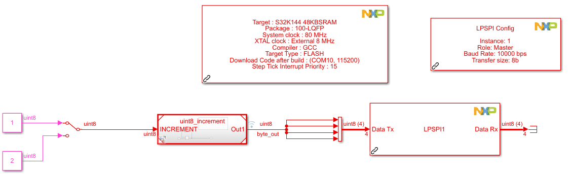
Top level model: JVCB3_TEST_TOP.
Change the MBD_S32K1xx_Config_Information to point to the COM port for your board (or switch to OpenSDA if you're using an evaluation board).
Go to Modelling tab and click on "Update Model".
Go to the "Apps" tab and click on Embedded Coder.
Click on "Build" and upload the model to the board. Observe that there is no SPI communication. Notice that the signal being fed into the LPSPI_Master_Transfer block is declared as "uint8 (4)" on the simulink model.
Navigate to the generated code at "<model root>\JVCB3_TEST_TOP_mbd_rtw\JVCB3_TEST_TOP.c"
Note on line 57:
/* Send data */
LPSPI_DRV_MasterTransferBlocking(1,
&JVCB3_TEST_TOP_B.TmpSignalConversionAtLPSPI_Master_TransferInport1[0],
&JVCB3_TEST_TOP_B.LPSPI_Master_Transfer[0], 1, 50);
}
And on line 42:
/* SignalConversion generated from: '<Root>/LPSPI_Master_Transfer' */
JVCB3_TEST_TOP_B.TmpSignalConversionAtLPSPI_Master_TransferInport1[0] =
rtb_byte_out;
JVCB3_TEST_TOP_B.TmpSignalConversionAtLPSPI_Master_TransferInport1[1] =
rtb_byte_out;
JVCB3_TEST_TOP_B.TmpSignalConversionAtLPSPI_Master_TransferInport1[2] =
rtb_byte_out;
JVCB3_TEST_TOP_B.TmpSignalConversionAtLPSPI_Master_TransferInport1[3] =
rtb_byte_out;
Navigate to JVCB3_TEST_TOP.h.
Note on line 37:
/* Block signals (default storage) */
typedef struct {
uint8_T TmpSignalConversionAtLPSPI_Master_TransferInport1[4];
uint8_T LPSPI_Master_Transfer[4]; /* '<Root>/LPSPI_Master_Transfer' */
} B_JVCB3_TEST_TOP_T;
The generated code is clearly a C array of 4 unit8's. However LPSPI_DRV_MasterTransferBlocking in being passed a length of 1 byte.
- 新着としてマーク
- ブックマーク
- 購読
- ミュート
- RSS フィードを購読する
- ハイライト
- 印刷
- 不適切なコンテンツを報告

- 新着としてマーク
- ブックマーク
- 購読
- ミュート
- RSS フィードを購読する
- ハイライト
- 印刷
- 不適切なコンテンツを報告
Have you tried setting the frame size to 8b in the SPI config block and sending a uint8[4] to the SPI transfer block? And of course with continuous transfer checked
- 新着としてマーク
- ブックマーク
- 購読
- ミュート
- RSS フィードを購読する
- ハイライト
- 印刷
- 不適切なコンテンツを報告
If you set it to 8bits, it drops chip select after each transfer of 8bits. This does not work if the peripheral is expecting 16bit before dropping chip select.
- 新着としてマーク
- ブックマーク
- 購読
- ミュート
- RSS フィードを購読する
- ハイライト
- 印刷
- 不適切なコンテンツを報告
I tried with 8b frame size and continuous transfer checked and it seems to work fine. I didn't connect the bus to anything so there is no reply.
This is running on the S32K144 EVB. But I have been running it on a proprietary board with the same MCU with these settings.


I attached the simple model if you want to compare the SPI settings.
- 新着としてマーク
- ブックマーク
- 購読
- ミュート
- RSS フィードを購読する
- ハイライト
- 印刷
- 不適切なコンテンツを報告
For what it's worth, the target tested SPI device in question is a PCB with a string of daisy chained 74164's and it wouldn't matter if CS is dropped between bytes or not. But my testing was done with continuous transfers enabled.
- 新着としてマーク
- ブックマーク
- 購読
- ミュート
- RSS フィードを購読する
- ハイライト
- 印刷
- 不適切なコンテンツを報告
Also there are other devices on other SPI ports, which have 16-bit, 32-bit, and 64-bit frame sizes, and WILL have an issue if chip select is dropped between bytes, so its pretty important that this gets fixed