
- Forums
- Product Forums
- General Purpose MicrocontrollersGeneral Purpose Microcontrollers
- i.MX Forumsi.MX Forums
- QorIQ Processing PlatformsQorIQ Processing Platforms
- Identification and SecurityIdentification and Security
- Power ManagementPower Management
- Wireless ConnectivityWireless Connectivity
- RFID / NFCRFID / NFC
- Advanced AnalogAdvanced Analog
- Neural Processing UnitsNeural Processing Units
- MCX Microcontrollers
- S32G
- S32K
- S32V
- MPC5xxx
- Other NXP Products
- S12 / MagniV Microcontrollers
- Powertrain and Electrification Analog Drivers
- Sensors
- Vybrid Processors
- Digital Signal Controllers
- 8-bit Microcontrollers
- ColdFire/68K Microcontrollers and Processors
- PowerQUICC Processors
- OSBDM and TBDML
- S32M
- S32Z/E
-
- Solution Forums
- Software Forums
- MCUXpresso Software and ToolsMCUXpresso Software and Tools
- CodeWarriorCodeWarrior
- MQX Software SolutionsMQX Software Solutions
- Model-Based Design Toolbox (MBDT)Model-Based Design Toolbox (MBDT)
- FreeMASTER
- eIQ Machine Learning Software
- Embedded Software and Tools Clinic
- S32 SDK
- S32 Design Studio
- GUI Guider
- Zephyr Project
- Voice Technology
- Application Software Packs
- Secure Provisioning SDK (SPSDK)
- Processor Expert Software
- Generative AI & LLMs
-
- Topics
- Mobile Robotics - Drones and RoversMobile Robotics - Drones and Rovers
- NXP Training ContentNXP Training Content
- University ProgramsUniversity Programs
- Rapid IoT
- NXP Designs
- SafeAssure-Community
- OSS Security & Maintenance
- Using Our Community
-
- Cloud Lab Forums
-
- Knowledge Bases
- ARM Microcontrollers
- i.MX Processors
- Identification and Security
- Model-Based Design Toolbox (MBDT)
- QorIQ Processing Platforms
- S32 Automotive Processing Platform
- Wireless Connectivity
- CodeWarrior
- MCUXpresso Suite of Software and Tools
- MQX Software Solutions
- RFID / NFC
- Advanced Analog
- Neural Processing Units
-
- NXP Tech Blogs
- Home
- :
- 汎用マイクロコントローラ
- :
- LPCマイクロコントローラ
- :
- Re: USB0_VBUS current draw higher than expected
USB0_VBUS current draw higher than expected
- RSS フィードを購読する
- トピックを新着としてマーク
- トピックを既読としてマーク
- このトピックを現在のユーザーにフロートします
- ブックマーク
- 購読
- ミュート
- 印刷用ページ
USB0_VBUS current draw higher than expected
- 新着としてマーク
- ブックマーク
- 購読
- ミュート
- RSS フィードを購読する
- ハイライト
- 印刷
- 不適切なコンテンツを報告
Content originally posted in LPCWare by jsdmichaud on Wed Feb 25 13:39:56 MST 2015
Hello,
We are working on a product that can be powered by USB. The uC used is the LPC4357. The VDDIO of the LPC4357 is seperate from the USB power. It can happen that the USB power is present on the board while the VDDIO is not present (regulator shutdowned). Looking to the LPC43xx user manual and the AN11392 application note, we learned that the USBx_VBUS (USB0_VBUS in our case) pin are 5V tolerant only when VDDIO power of the LPC is present.
So we needed a way to reduce the USB voltage at the USB0_VBUS. In the AN11392 application note there's a recommended solution by using a voltage divider with a 24kohm and a 39kohm resistor. This solution doesn't work for us because the voltage measured at the USB0_VBUS pin is a lot lower than expected.
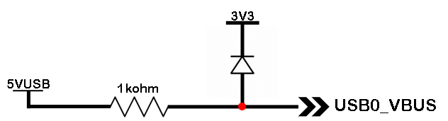
So we tried another solution by using a series resistor and a simple diode between the USB0_VBUS pin and our 3.3V power bus, which is the VDDIO voltage of the LPC. Attached is the little circuit we used toreduce the voltage at USB0_VBUS. Here are results of what we measured:
- When VUSB is at 5V and the 3.3V bus (VDDIO) is not active, voltage measured at USB0_VBUS is 1.7V. We get this result because the 3.3V is around 1V (not 0V) because of the voltage going accross the protection diode in the LPC4357 because VDDIO is not present. So 1V + Vf of the diode = 1.7V
- When VUSB is at 5V and the 3.3V bus (VDDIO) is active and we are in the bootloader of the application (no initialization of the USB interface), voltage measured at USB0_VBUS is 4V. **We were expecting (3.3V + Vf of the diode) = 4V. So this is correct at this point.
- When VUSB is at 5V and the 3.3V bus (VDDIO) is active and the initialization of the USB interface is done, voltage measured at USB0_VBUS is 2.9V. **We were expecting (3.3V + Vf of the diode) = 4V. At this point USB0_VBUS pin seems to draw too much current. (5V - 2.8V)/ 1000ohm = 2.2mA which seems a lot for this kind of pin.
This current draw could also be the cause of the problem with the voltage divider solution recommended in the AN11392 application note.
Is there any other solution ? And, is it normal that this pin is acting like that when the USB is initialized in the application code.
Thnaks a lot
- 新着としてマーク
- ブックマーク
- 購読
- ミュート
- RSS フィードを購読する
- ハイライト
- 印刷
- 不適切なコンテンツを報告
For anyone experiencing the same issue: The 2mA current draw is most likely caused by the vbus discharge bit being set (bit OTGSC->VD, see 25.6.16 in the LPC43xx user manual). This enables an internal pulldown of about 1.2kOhm.
The usb library sets this bit by default, which is a bug i think.
If you disable the bit right after calling USB_Init(), a voltage divider should work just fine:
Quote:
USB_Init(corenum, USB_MODE_Device);
LPC_USB0->OTGSC &= ~(1<<0);
The current consumed by the Vbus pin in this case is < 50uA instead of 2mA.
- 新着としてマーク
- ブックマーク
- 購読
- ミュート
- RSS フィードを購読する
- ハイライト
- 印刷
- 不適切なコンテンツを報告
We have found that different revisions of the LPC4350 silicon require different currents to pull UP the USB0_VBUS line to a valid logic high. We originally used a 15K series resistor between the USB cable 5V pin and the USB0_VBUS pin on the LPC4350 and a 33.2K resistor in parallel with a 3.6 V zener diode from the USB0_VBUS pin to ground. We had to change the series 15K to a 1K to work on older revision silicon.
For example, it did not work with the following marked part:
LPC4359FET256
PFM906.4 10
ESD1149ZRY
Newer versions of the silicon worked ok with the 15 K series resistor:
LPC4350FET256
SC4K9 20
9SD14190C
- 新着としてマーク
- ブックマーク
- 購読
- ミュート
- RSS フィードを購読する
- ハイライト
- 印刷
- 不適切なコンテンツを報告
Hi,
in the past I have had a similar problem but I have had no response.
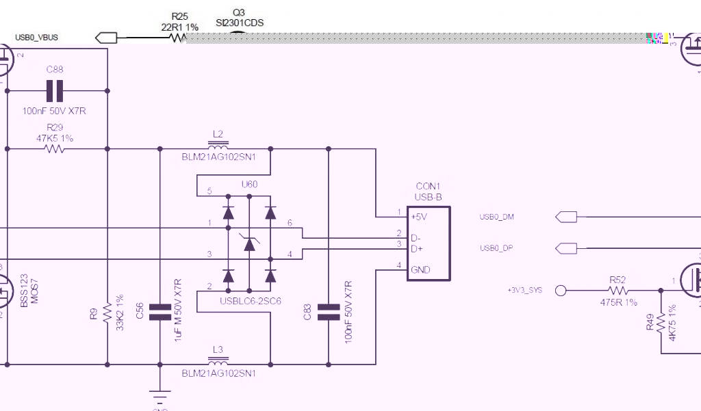
I have found an abnormal absorption on pin VBUS0 when the MCU is turned on in BOOT mode for programming with DFU via USB0: http://www.lpcware.com/content/forum/lpc4357-problem-usb0-dfu-mode
The solution I adopted has been to use two small MOSFET as shown in the attached image.
BR
Fabio