
- Forums
- Product Forums
- General Purpose MicrocontrollersGeneral Purpose Microcontrollers
- i.MX Forumsi.MX Forums
- QorIQ Processing PlatformsQorIQ Processing Platforms
- Identification and SecurityIdentification and Security
- Power ManagementPower Management
- Wireless ConnectivityWireless Connectivity
- RFID / NFCRFID / NFC
- Advanced AnalogAdvanced Analog
- Neural Processing UnitsNeural Processing Units
- MCX Microcontrollers
- S32G
- S32K
- S32V
- MPC5xxx
- Other NXP Products
- S12 / MagniV Microcontrollers
- Powertrain and Electrification Analog Drivers
- Sensors
- Vybrid Processors
- Digital Signal Controllers
- 8-bit Microcontrollers
- ColdFire/68K Microcontrollers and Processors
- PowerQUICC Processors
- OSBDM and TBDML
- S32M
- S32Z/E
-
- Solution Forums
- Software Forums
- MCUXpresso Software and ToolsMCUXpresso Software and Tools
- CodeWarriorCodeWarrior
- MQX Software SolutionsMQX Software Solutions
- Model-Based Design Toolbox (MBDT)Model-Based Design Toolbox (MBDT)
- FreeMASTER
- eIQ Machine Learning Software
- Embedded Software and Tools Clinic
- S32 SDK
- S32 Design Studio
- GUI Guider
- Zephyr Project
- Voice Technology
- Application Software Packs
- Secure Provisioning SDK (SPSDK)
- Processor Expert Software
- Generative AI & LLMs
-
- Topics
- Mobile Robotics - Drones and RoversMobile Robotics - Drones and Rovers
- NXP Training ContentNXP Training Content
- University ProgramsUniversity Programs
- Rapid IoT
- NXP Designs
- SafeAssure-Community
- OSS Security & Maintenance
- Using Our Community
-
- Cloud Lab Forums
-
- Knowledge Bases
- ARM Microcontrollers
- i.MX Processors
- Identification and Security
- Model-Based Design Toolbox (MBDT)
- QorIQ Processing Platforms
- S32 Automotive Processing Platform
- Wireless Connectivity
- CodeWarrior
- MCUXpresso Suite of Software and Tools
- MQX Software Solutions
- RFID / NFC
- Advanced Analog
- Neural Processing Units
-
- NXP Tech Blogs
- Home
- :
- 製品フォーラム
- :
- ColdFire/68Kマイクロコントローラとプロセッサ
- :
- Re: MCF54418 Flexbus Application question
MCF54418 Flexbus Application question
- RSS フィードを購読する
- トピックを新着としてマーク
- トピックを既読としてマーク
- このトピックを現在のユーザーにフロートします
- ブックマーク
- 購読
- ミュート
- 印刷用ページ
- 新着としてマーク
- ブックマーク
- 購読
- ミュート
- RSS フィードを購読する
- ハイライト
- 印刷
- 不適切なコンテンツを報告
Hi
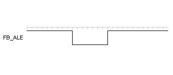
First of all, I am a beginner. Recently encountered a problem when using Flexbus, connect FPGA. FB_ALE output signal wrong(See Appendix,Described in the reference manual, which should be active high).
Register set(In BSP Configuration) :PAR_FBCTL = f5.(set FB_ALE),PPMLR0 = fbc2f300.(enable FB Clock).
I would like to ask whether my configuration is incorrect, please enlighten me.
Thanks!
Code in Annex
Original Attachment has been moved to: Flexbus.txt.zip
解決済! 解決策の投稿を見る。
- 新着としてマーク
- ブックマーク
- 購読
- ミュート
- RSS フィードを購読する
- ハイライト
- 印刷
- 不適切なコンテンツを報告
I would suggest supplying a real oscilloscope capture covering multiple cycles, together with some other signals in the same capture, like the Chip Selects.
> See Appendix,Described in the reference manual
I can't find any Appendix in my MCF5118 Reference Manual. There's Chapter 45 and then the last page. You should give exact details on what diagram in which chapter of what manual you're reading.
You should be looking at "Figure 20-8. Basic Read-Bus Cycle" and the following diagrams. Better, for timing information you should not read the Reference Manual, but should refer to "Figure 11. FlexBus read timing" in "4.10 FlexBus timing specifications" in the Data Sheet.
For back-to-back Read Cycles on the Flexbus I would expect to see ALE go Active/High during the S0 clock period (when CS is Inactive/High) and then go Inactive/Low during the rest of the clock cycles, while CS is Active/Low.
In that sens the ALO and CS signals are similar, and I think you're misinterpreting the High and Low parts.
> one clock cycle of 16ns(FB_CLK:62.5MHz), but measured approximately 400ns low pulse
So you have about 25 wait states?
Tom
- 新着としてマーク
- ブックマーク
- 購読
- ミュート
- RSS フィードを購読する
- ハイライト
- 印刷
- 不適切なコンテンツを報告
In addition, according to the manual, FB_ALE signal for one clock cycle of 16ns(FB_CLK:62.5MHz), but measured approximately 400ns low pulse, FB_CS signal as well.
- 新着としてマーク
- ブックマーク
- 購読
- ミュート
- RSS フィードを購読する
- ハイライト
- 印刷
- 不適切なコンテンツを報告
I would suggest supplying a real oscilloscope capture covering multiple cycles, together with some other signals in the same capture, like the Chip Selects.
> See Appendix,Described in the reference manual
I can't find any Appendix in my MCF5118 Reference Manual. There's Chapter 45 and then the last page. You should give exact details on what diagram in which chapter of what manual you're reading.
You should be looking at "Figure 20-8. Basic Read-Bus Cycle" and the following diagrams. Better, for timing information you should not read the Reference Manual, but should refer to "Figure 11. FlexBus read timing" in "4.10 FlexBus timing specifications" in the Data Sheet.
For back-to-back Read Cycles on the Flexbus I would expect to see ALE go Active/High during the S0 clock period (when CS is Inactive/High) and then go Inactive/Low during the rest of the clock cycles, while CS is Active/Low.
In that sens the ALO and CS signals are similar, and I think you're misinterpreting the High and Low parts.
> one clock cycle of 16ns(FB_CLK:62.5MHz), but measured approximately 400ns low pulse
So you have about 25 wait states?
Tom
- 新着としてマーク
- ブックマーク
- 購読
- ミュート
- RSS フィードを購読する
- ハイライト
- 印刷
- 不適切なコンテンツを報告
Tom Evans 撰写:
So you have about 25 wait states?
Tom
Thank you for your answer, depending on your tips, I removed wait States, tested once again , I was wrong before the test, did not observe the details FB_ALE signals, the signals are as follows. In other words, my previous configuration of FLEXBUS is correct.
Thanks.

- 新着としてマーク
- ブックマーク
- 購読
- ミュート
- RSS フィードを購読する
- ハイライト
- 印刷
- 不適切なコンテンツを報告
Hello,
Thank you for your post, however please consider moving it to the right community place (e.g.ColdFire/68K Microcontrollers and Processors ) to get it visible for active members.
For details please see general advice Where to post a Discussion?
Thank you for using Freescale Community.