
- Forums
- Product Forums
- General Purpose MicrocontrollersGeneral Purpose Microcontrollers
- i.MX Forumsi.MX Forums
- QorIQ Processing PlatformsQorIQ Processing Platforms
- Identification and SecurityIdentification and Security
- Power ManagementPower Management
- Wireless ConnectivityWireless Connectivity
- RFID / NFCRFID / NFC
- Advanced AnalogAdvanced Analog
- Neural Processing UnitsNeural Processing Units
- MCX Microcontrollers
- S32G
- S32K
- S32V
- MPC5xxx
- Other NXP Products
- S12 / MagniV Microcontrollers
- Powertrain and Electrification Analog Drivers
- Sensors
- Vybrid Processors
- Digital Signal Controllers
- 8-bit Microcontrollers
- ColdFire/68K Microcontrollers and Processors
- PowerQUICC Processors
- OSBDM and TBDML
- S32M
- S32Z/E
-
- Solution Forums
- Software Forums
- MCUXpresso Software and ToolsMCUXpresso Software and Tools
- CodeWarriorCodeWarrior
- MQX Software SolutionsMQX Software Solutions
- Model-Based Design Toolbox (MBDT)Model-Based Design Toolbox (MBDT)
- FreeMASTER
- eIQ Machine Learning Software
- Embedded Software and Tools Clinic
- S32 SDK
- S32 Design Studio
- GUI Guider
- Zephyr Project
- Voice Technology
- Application Software Packs
- Secure Provisioning SDK (SPSDK)
- Processor Expert Software
- Generative AI & LLMs
-
- Topics
- Mobile Robotics - Drones and RoversMobile Robotics - Drones and Rovers
- NXP Training ContentNXP Training Content
- University ProgramsUniversity Programs
- Rapid IoT
- NXP Designs
- SafeAssure-Community
- OSS Security & Maintenance
- Using Our Community
-
- Cloud Lab Forums
-
- Knowledge Bases
- ARM Microcontrollers
- i.MX Processors
- Identification and Security
- Model-Based Design Toolbox (MBDT)
- QorIQ Processing Platforms
- S32 Automotive Processing Platform
- Wireless Connectivity
- CodeWarrior
- MCUXpresso Suite of Software and Tools
- MQX Software Solutions
- RFID / NFC
- Advanced Analog
- Neural Processing Units
-
- NXP Tech Blogs

Hello!
We are developing custom board using iMX6ULL (MCIMX6Y2xxx05).
Board has microSD card holder which pins are routed to following pins (eSDHC1)
IOMUXC_SW_PAD_CTL_PAD_SD1_CMD
IOMUXC_SW_PAD_CTL_PAD_SD1_CLK
IOMUXC_SW_PAD_CTL_PAD_SD1_DATA0
IOMUXC_SW_PAD_CTL_PAD_SD1_DATA1
IOMUXC_SW_PAD_CTL_PAD_SD1_DATA2
IOMUXC_SW_PAD_CTL_PAD_SD1_DATA3
and has eMMC (MTFC4GACAJCN-4M IT), its pins route to following pins (eSDHC2)
IOMUXC_SW_PAD_CTL_PAD_NAND_RE_B
IOMUXC_SW_PAD_CTL_PAD_NAND_WE_B
IOMUXC_SW_PAD_CTL_PAD_NAND_DATA00
IOMUXC_SW_PAD_CTL_PAD_NAND_DATA01
IOMUXC_SW_PAD_CTL_PAD_NAND_DATA02
IOMUXC_SW_PAD_CTL_PAD_NAND_DATA03
IOMUXC_SW_PAD_CTL_PAD_NAND_ALE
I built u-boot and ran it via Lauterbach Trace 32. Both eMMC and SD card were detected successfully and i could list partitions on SD and make hw partitioning on eMMC. So there is OK from hardware side. I used DDR3 register programming aid v1.1 for generating imximage.conf, i added initialization of eMMC and SD pins to this file.
Then i program u-boot.imx to eMMC (via Trace 32) and SD card (using dd utility) at address 0x400 in accordance with ref manual.
After this i made a small program that blinks leds. In linker script i set entry point as 0x87800000 and this app works perfect if i run it from RAM using Trace32.
I blew fuses for SD as
&BOOT_CFG1=0x40 ; SD,
                ; Fast Boot: 0 - Regular
                ; SD/SDXC speed: 00 - Normal/SDR12
                ; SD Power Cycle Enable: 0 - No power cycle
                ; SD Loopback Clock Source Sel(for SDR50 and SDR104 only) 0 - through SD pad
&BOOT_CFG2=0x20 ; SD Calibration Step: 00 - 1 delay cell
                ; Bus Width: 1 - 4-bit
                ; Port Select: 00 - eSDHC1
                ; Boot Frequencies (ARM/DDR): 0 - 500 / 400 MHz
                ; SD VOLTAGE SELECTION: 0 - 3.3V
&BOOT_CFG3=0x00
&BOOT_CFG4=0x00
&Fuse450=&BOOT_CFG4<<24+&BOOT_CFG3<<16+&BOOT_CFG2<<8+&BOOT_CFG1
&Fuse460=0x10 ; BT_FUSE_SEL
and for eMMC as
&BOOT_CFG1=0x6E ; eMMC,
                ; Fast Boot: 0 - Regular
                ; SD/MMC Speed: 1- Normal
                ; Fast Boot Acknowledge Disable: 1 - Boot Ack Disabled
                ; SD Power Cycle Enable: 0 - No power cycle
                ; SD Loopback Clock Source Sel(for SDR50 and SDR104 only) 0 - through SD pad
&BOOT_CFG2=0xA8 ; Bus Width: 101 - 4-bit DDR (MMC 4.4)
                ; Port Select: 01 - eSDHC2
                ; Boot Frequencies (ARM/DDR): 0 - 500 / 400 MHz
                ; SD VOLTAGE SELECTION: 0 - 3.3V
&BOOT_CFG3=0x00
&BOOT_CFG4=0x00

&Fuse450=&BOOT_CFG4<<24+&BOOT_CFG3<<16+&BOOT_CFG2<<8+&BOOT_CFG1
&Fuse460=0x10 ; BT_FUSE_SEL
I used mkimage utility to make binary with DCD section (/tools/mkimage -n u-boot.cfgout -T imximage -e 0x87800000 -d leds.bin leds.imx)
I checked IVT and DCD, it had been generated correctly
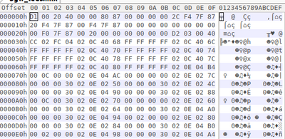
And app starts at 0xC00 (+0x400=0x1000)
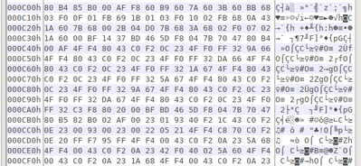
I put and verified this binary to eMMC and it didn't start after reboot.
I used to oscilloscope and logic analyzer to check
I can see BootROM sends several commands to eMMC and eMMC responded to them. Then MCU changes freq to 20 Mhz, sends a few more commands and after this stops clocking.
Assigns relative address to the card
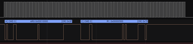
Addressed card sends its card-specific data
(CSD) on the CMD line

Changing speed and CMD0 again

Did I miss something? Is there any way to get info from BootROM why it can't boot from eMMC or SD?
已解决! 转到解答。
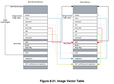
It's not clear enough explained in Reference Manual. That BootData.start means the destination address where BootROM will copy BootData.Length bytes from eMMC starting from address 0x00000000.
I've changed start address to (application address - 0x1000) and eventually it started from eMMC in configuration entrypoint = 0x87800000
Thank you for support.


@Yuri
Hello!
Yesterday i connected a board to another computer and got info from i.MX Boot Utility.
*********************************************************
    i.MX/Vybrid Boot Utility (2.5.0 Beta) for i.MX6 UltraLiteLite
    Java Version
    NXP Semiconductor, Inc.
*********************************************************

SBMR1  = 0x0000A86E
   Boot_cfg_1  = 0x6E
   Boot_cfg_2  = 0xA8
   Boot_cfg_3  = 0x00
   Boot_cfg_4  = 0x00

SBMR2     = 0x00000011
   BMOD     = 00   Boot from Fuses
   BT_FUSE_SEL   = 1
   DIR_BT_DIS     = 0
   SEC_CONFIG     = 01

iROM Version  = 0x11

WDOG Fuse Disabled

Persistent Reg Value: 0x00000000

Analog Digprog  = 0x00000000
   Device  = i.MX6 UltraLiteLite
   Silicon Rev  = 1.0
Log Buffer Listing:


Valid IVT Header Found!

Header Code:  d1002041
Entry Adr:  87800000
Reserved1:  00000000
DCD Adr:  80000440
Boot Data Adr:  80000420
Self Adr:  00000000
CSF Adr:  00000000
Reserved2:  00000000


DCD Parsing Information.
Currently assumes only 32bit Writes are used.
Write 32bits: 020c4068 = ffffffff
Write 32bits: cc000c14 = 020c406c
Write 32bits: ffffffff = cc000c14
Write 32bits: 020c4070 = ffffffff
Write 32bits: cc000c14 = 020c4074
Write 32bits: ffffffff = cc000c14
Write 32bits: 020c4078 = ffffffff
Write 32bits: cc000c14 = 020c407c
Write 32bits: ffffffff = cc000c14
Write 32bits: 020c4080 = ffffffff
Write 32bits: cc000c14 = 020e04b4
Write 32bits: 000c0000 = cc000c14
Write 32bits: 020e04ac = 00000000
Write 32bits: cc000c14 = 020e027c
Write 32bits: 00000030 = cc000c14
Write 32bits: 020e0250 = 00000030
Write 32bits: cc000c14 = 020e024c
Write 32bits: 00000030 = cc000c14
Write 32bits: 020e0490 = 00000030
Write 32bits: cc000c14 = 020e0288
Write 32bits: 000c0030 = cc000c14
Write 32bits: 020e0270 = 00000000
Write 32bits: cc000c14 = 020e0260
Write 32bits: 00000030 = cc000c14
Write 32bits: 020e0264 = 00000030
Write 32bits: cc000c14 = 020e04a0
Write 32bits: 00000030 = cc000c14
Write 32bits: 020e0494 = 00020000
Write 32bits: cc000c14 = 020e0280
Write 32bits: 00000030 = cc000c14
Write 32bits: 020e0284 = 00000030
Write 32bits: cc000c14 = 020e04b0
Write 32bits: 00020000 = cc000c14
Write 32bits: 020e0498 = 00000030
Write 32bits: cc000c14 = 020e04a4
Write 32bits: 00000030 = cc000c14
Write 32bits: 020e0244 = 00000030
Write 32bits: cc000c14 = 020e0248
Write 32bits: 00000030 = cc000c14
Write 32bits: 021b001c = 00008000
Write 32bits: cc000c14 = 021b0800
Write 32bits: a1390003 = cc000c14
Write 32bits: 021b080c = 0011000d
Write 32bits: cc000c14 = 021b083c
Write 32bits: 41440144 = cc000c14
Write 32bits: 021b0848 = 40403e40
Write 32bits: cc000c14 = 021b0850
Write 32bits: 40402c2a = cc000c14
Write 32bits: 021b081c = 33333333
Write 32bits: cc000c14 = 021b0820
Write 32bits: 33333333 = cc000c14
Write 32bits: 021b082c = f3333333
Write 32bits: cc000c14 = 021b0830
Write 32bits: f3333333 = cc000c14
Write 32bits: 021b08c0 = 00921012
Write 32bits: cc000c14 = 021b08b8
Write 32bits: 00000800 = cc000c14
Write 32bits: 021b0004 = 00010024
Write 32bits: cc000c14 = 021b0008
Write 32bits: 1b777070 = cc000c14
Write 32bits: 021b000c = 666a5393
Write 32bits: cc000c14 = 021b0010
Write 32bits: b66d0b67 = cc000c14
Write 32bits: 021b0014 = 01ff00db
Write 32bits: cc000c14 = 021b0018
Write 32bits: 00201740 = cc000c14
Write 32bits: 021b002c = 000026d2
Write 32bits: cc000c14 = 021b0030
Write 32bits: 006a1023 = cc000c14
Write 32bits: 021b0040 = 00000043
Write 32bits: cc000c14 = 021b0000
Write 32bits: 82180000 = cc000c14
Write 32bits: 021b001c = 02208032
Write 32bits: cc000c14 = 021b001c
Write 32bits: 00008033 = cc000c14
Write 32bits: 021b001c = 00048031
Write 32bits: cc000c14 = 021b001c
Write 32bits: 15208030 = cc000c14
Write 32bits: 021b001c = 04008040
Write 32bits: cc000c14 = 021b0020
Write 32bits: 00000800 = cc000c14
Write 32bits: 021b0818 = 00000227
Write 32bits: cc000c14 = 021b0004
Write 32bits: 00015564 = cc000c14
Write 32bits: 021b0404 = 00011006
Write 32bits: cc000c14 = 021b001c
Write 32bits: 00000000 = cc000c14
Write 32bits: 020e0178 = 00000001
Write 32bits: cc000c14 = 020e017c
Write 32bits: 00000001 = cc000c14
Write 32bits: 020e0180 = 00000001
Write 32bits: cc000c14 = 020e0184
Write 32bits: 00000001 = cc000c14
Write 32bits: 020e0188 = 00000001
Write 32bits: cc000c14 = 020e018c
Write 32bits: 00000001 = cc000c14
Write 32bits: 020e01a0 = 00000001
Write 32bits: cc000c14 = 020e0670
Write 32bits: 00000002 = cc000c14
Write 32bits: 020e0678 = 00000002
Write 32bits: cc000c14 = 020e067c
Write 32bits: 00000002 = cc000c14
Write 32bits: 020e0680 = 00000002
Write 32bits: cc000c14 = 020e0684
Write 32bits: 00000001 = cc000c14
Write 32bits: 020e0688 = 00000002
Write 32bits: cc000c14 = 020e0404
Write 32bits: 00010059 = cc000c14
Write 32bits: 020e0408 = 00017059
Write 32bits: cc000c14 = 020e040c
Write 32bits: 00017059 = cc000c14
Write 32bits: 020e0410 = 00017059
Write 32bits: cc000c14 = 020e0414
Write 32bits: 00017059 = cc000c14
Write 32bits: 020e0418 = 00017059
Write 32bits: cc000c14 = 020e042c
Write 32bits: 00017059 = cc000c14
Write 32bits: 020e01bc = 00000000
Write 32bits: cc000c14 = 020e01c0
Write 32bits: 00000000 = cc000c14
Write 32bits: 020e01c4 = 00000000
Write 32bits: cc000c14 = 020e01c8
Write 32bits: 00000000 = cc000c14
Write 32bits: 020e01cc = 00000000
Write 32bits: cc000c14 = 020e01d0
Write 32bits: 00000000 = cc000c14
Write 32bits: 020e0448 = 00017059
Write 32bits: cc000c14 = 020e044c
Write 32bits: 00010059 = cc000c14
Write 32bits: 020e0450 = 00017059
Write 32bits: cc000c14 = 020e0454
Write 32bits: 00017059 = cc000c14
Write 32bits: 020e0458 = 00017059
Write 32bits: cc000c14 = 020e045c
Write 32bits: 00017059 = cc000c14
Write 32bits: 020e0164 = 00000001
Write 32bits: cc000c14 = 020e0164
Write 32bits: 00000005 = 00000000
Write 32bits: 00000000 = 00000000
Write 32bits: 00000000 = 00000000
Write 32bits: 00000000 = 00000000
Write 32bits: 00000000 = 00000000
Write 32bits: 00000000 = 00000000
Here's a header of app that i uploaded
readelf -h bgw_leds.elf
ELF Header:
  Magic:   7f 45 4c 46 01 01 01 00 00 00 00 00 00 00 00 00
  Class:                             ELF32
  Data:                              2's complement, little endian
  Version:                           1 (current)
  OS/ABI:                            UNIX - System V
  ABI Version:                       0
  Type:                              EXEC (Executable file)
  Machine:                           ARM
  Version:                           0x1
  Entry point address:               0x87800000
  Start of program headers:          52 (bytes into file)
  Start of section headers:          2857996 (bytes into file)
  Flags:                             0x5000400, Version5 EABI, hard-float ABI
  Size of this header:               52 (bytes)
  Size of program headers:           32 (bytes)
  Number of program headers:         1
  Size of section headers:           40 (bytes)
  Number of section headers:         8
  Section header string table index: 7
Also i attached the app src and elf that i uploaded to eMMC and a dump of first 512kb of eMMC
By the way, i faced some strange behavior of one of boards i have. this board also has blown fuses to load from eMMC. when i power up this board and it fails to boot it doesn't go to serial downloader mode.
i used the same dcd, same app, same location on emmc. there is only one difference: it has following configuration of fuses
SBMR1  = 0x00002860
   Boot_cfg_1  = 0x60
   Boot_cfg_2  = 0x28
   Boot_cfg_3  = 0x00
   Boot_cfg_4  = 0x00

SBMR2     = 0x00000011
Hello @Yuri!
Yes, i use the same ddr configuration.
I use this imximage.cfg file for initialization DDR in Trace32 before uploading stress test tool elf and for creating imx image using mximage utility
Hello, Yuri!
Let me tell how I try to boot from SD on EVK. I used MCIMX6UL-EVK board.
Using Yocto I built recipe core-image-minimal and ran it from SD. Therefore I’m sure this board can boot from SD card.
I soldered two LEDs to pins GPIO1_00 and GPIO1_01 (pins 1 and 2 on J1706)
I made a new project in Eclipse. As toolchain I used a toolchain that I built using recipe meta-toolchain before.
After compilation I got ELF and BIN (arm-none-eabi-objcopy -v -O binary bgw_leds.elf bgw_leds.bin). The ELF had the following header
ELF Header:
  Magic:   7f 45 4c 46 01 01 01 00 00 00 00 00 00 00 00 00
  Class:                             ELF32
  Data:                              2's complement, little endian
  Version:                           1 (current)
  OS/ABI:                            UNIX - System V
  ABI Version:                       0
  Type:                              EXEC (Executable file)
  Machine:                           ARM
  Version:                           0x1
  Entry point address:               0x87800000
  Start of program headers:          52 (bytes into file)
  Start of section headers:          73956 (bytes into file)
  Flags:                             0x5000400, Version5 EABI, hard-float ABI
  Size of this header:               52 (bytes)
  Size of program headers:           32 (bytes)
  Number of program headers:         1
  Size of section headers:           40 (bytes)
  Number of section headers:         8
  Section header string table index: 7
To check if app works properly, I loaded it to board using Trace32. As DDR configuration I used dcd.config I copied from SDK (SDK_2.2_MCIM6ULL\tools\imgutil\evkmcimx6ull\dcd.config).
I used the following script
RESet
SYStem.RESet
SYStem.CPU IMX6ULTRALITE
SYStem.Option ResBreak OFF
IF VERSION.BUILD()<92177.
(
SYStem.Option WaitReset 10ms
)
ELSE
(
  SYStem.Option WaitIDCODE 1.5s
)
SYStem.JtagClock CTCK 10MHz
SYStem.Up

DO ~~~~/scripts/dcd_interpreter "~~~~/../evk_dcd.config"
Data.LOAD.Elf "/home/user/eclipse-workspace/bgw_leds/EVK/bgw_leds.elf"
Go
App ran successfully, LEDs blinked as expected.
After this I prepared dcd.bin using dcdgen.bin utility from SDK
dcdgen.bin /opt/SDK_2.2_MCIM6UL/tools/imgutil/evkmcimx6ul/dcd.config /opt/SDK_2.2_MCIM6UL/tools/imgutil/evkmcimx6ul/dcd.binThen I made IMX image using utility imgutil.bin from SDK
./imgutil.bin --combine base_addr=0x80000000 ivt_offset=0x400 app_offset=0x1000 dcd_file=/opt/SDK_2.2_MCIM6UL/tools/imgutil/evkmcimx6ul/dcd.bin app_file=/home/user/eclipse-workspace/bgw_leds/EVK/bgw_leds.bin ofile=/home/user/eclipse-workspace/bgw_leds/EVK/bgw_leds.imx image_entry_point=0x87800000
As result I got IMX file that contained IVT, DCD and app at their places.
Combined Image Info:
--------------------------------------
   base_addr         = 0x80000000
   ivt_offset        = 0x00000400
   hab_ivt.hdr       = 0x412000d1
   hab_ivt.entry     = 0x87800000
   hab_ivt.self      = 0x80000400
   hab_ivt.csf       = 0x00000000
   hab_ivt.boot_data = 0x80000420
   hab_ivt.dcd       = 0x80000440
   boot_data.start   = 0x80000000
   boot_data.size    = 0x00002cac
   boot_data.plugin  = 0x00000000

 Info for CSF file generation
--------------------------------------
   ivt_addr  = 0x80000400, ivt_offset  = 0x00000400
   app_addr  = 0x80001000, app_offset  = 0x00001000, app_size = 0x00001cc0
Then I put this file to microSD card
dd if=/home/user/eclipse-workspace/bgw_leds/EVK/bgw_leds.imx of=/dev/sdb bs=1024 conv=fsync
Inserted SD card into holder on EVK board and restarted, but MCU couldn’t boot from SD and run app
What do I do wrong? the project and Trace32 scripts are attached
Hello, @Yuri
Where i can find an info about BootRom sequence after it loaded first 4KB to RAM and processed DCD.
There is a gap between processing IVT and jumping to entry point.
the most examples including U-boot have entry point 0x87800000. I don't understand how my app that is placed at offset 0x1000 will get at this address.
Typical U-boot.imx IVT looks like this

U-boot bin is located at 0x1000, but boot_data says it starts from 0x877ff000
In my previous post i told about a simple project. It had the following IVT and it didn't run from eMMC

I changed entry point to 0x80001000 and rebuilt imx image, after this app could be running from eMMC
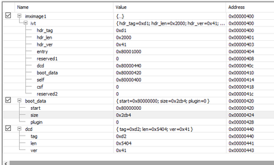
Can you explain BootROM behaviour regarding boot_data? Does BootROM copy app (boot_data.size bytes) from eMMC at 0x1000 offset to RAM at boot_data.start address? and then jumps at address ivt.entry?
@georgemakarov
Hello,
Yes, at first, 4 KB of data from the eMMC device is copied to the
internal RAM. After checking the Image Vector Table header value (0xD1) from
program image, the ROM code performs a DCD check. After a successful DCD
extraction, the ROM code extracts from the Boot Data Structure the destination pointer
and length of image to be copied to the RAM device from where the code execution
occurs.
Image Vector Table Offset for eMMC is 1 Kbyte = 0x400 bytes.
Figure 8-21 (Image Vector Table) of i.MX 6UL RM shows how data are located
in boot device and in RAM.
Regards,
Yuri.
It's not clear enough explained in Reference Manual. That BootData.start means the destination address where BootROM will copy BootData.Length bytes from eMMC starting from address 0x00000000.
I've changed start address to (application address - 0x1000) and eventually it started from eMMC in configuration entrypoint = 0x87800000
Thank you for support.
Hello @Yuri
Mentioning ELF I meant I use ELF to run via JTAG
&elf="~~~~/ddr_stress_tester_jtag_v3.00/ddr-test-uboot-jtag-mx6ull.elf"
Data.LOAD.Elf "&elf"
and in prior to make IMX image I make BIN from ELF via objcopy utility
arm-none-eabi-objcopy -v -O binary "${BuildArtifactFileName}" "${BuildArtifactFileBaseName}.bin
and imgutil.bin
imgutil --combine base_addr=0x80000000 ivt_offset=0x400 app_offset=0x1000 dcd_file=dcd.bin app_file=leds.bin ofile=leds.imx image_entry_point=0x87800000
for building dcd.bin i use the same imximage.cfg that i use in trace32 and for builiding u-boot
============================================
        DDR Stress Test (3.0.0)
        Build: Dec 14 2018, 14:21:15
        NXP Semiconductors.
============================================

============================================
        Chip ID
CHIP ID = i.MX6 UltraLiteLite(0x65)
(0x65)
Internal Revision = TO1.1
============================================

============================================
        Boot Configuration
SRC_SBMR1(0x020d8004) = 0x00002860
SRC_SBMR2(0x020d801c) = 0x00000011
============================================
I took another board, DDR had been calibrated and passed stress tests well
Boot configuration from DDR stress tool matches to fuses configuration.
&BOOT_CFG1=0x60 ; eMMC,
                ; Fast Boot: 0 - Regular
                ; SD/MMC Speed: 0 - High
                ; Fast Boot Acknowledge Disable: 0 - Boot Ack Enabled
                ; SD Power Cycle Enable: 0 - No power cycle
                ; SD Loopback Clock Source Sel(for SDR50 and SDR104 only) 0 - through SD pad
&BOOT_CFG2=0x28 ; Bus Width: 001 - 4-bit
                ; Port Select: 01 - eSDHC2
                ; Boot Frequencies (ARM/DDR): 0 - 500 / 400 MHz
                ; SD VOLTAGE SELECTION: 0 - 3.3V
&BOOT_CFG3=0x00
&BOOT_CFG4=0x00

&Fuse450=&BOOT_CFG4<<24+&BOOT_CFG3<<16+&BOOT_CFG2<<8+&BOOT_CFG1
&Fuse460=0x10 ; BT_FUSE_SEL
on this board i didn't blow some fuse concerning fast boot. Ref man says it will boot in normal mode if fast boot fails.
Unfortunately i don't have an analyzer that could read data from CMD line at 20 Mhz
@Yuri
Yuri, in this topic (https://community.nxp.com/t5/i-MX-Processors/i-MX6-Boot-Mode-setting/m-p/666617/highlight/true#M1025... you mentioned it's possible "to create request to get boot utility to review boot log" . How can i do this?
