- Forums
- Product Forums
- General Purpose MicrocontrollersGeneral Purpose Microcontrollers
- i.MX Forumsi.MX Forums
- QorIQ Processing PlatformsQorIQ Processing Platforms
- Identification and SecurityIdentification and Security
- Power ManagementPower Management
- Wireless ConnectivityWireless Connectivity
- RFID / NFCRFID / NFC
- MCX Microcontrollers
- S32G
- S32K
- S32V
- MPC5xxx
- Other NXP Products
- S12 / MagniV Microcontrollers
- Powertrain and Electrification Analog Drivers
- Sensors
- Vybrid Processors
- Digital Signal Controllers
- 8-bit Microcontrollers
- ColdFire/68K Microcontrollers and Processors
- PowerQUICC Processors
- OSBDM and TBDML
- S32M
-
- Solution Forums
- Software Forums
- MCUXpresso Software and ToolsMCUXpresso Software and Tools
- CodeWarriorCodeWarrior
- MQX Software SolutionsMQX Software Solutions
- Model-Based Design Toolbox (MBDT)Model-Based Design Toolbox (MBDT)
- FreeMASTER
- eIQ Machine Learning Software
- Embedded Software and Tools Clinic
- S32 SDK
- S32 Design Studio
- GUI Guider
- Zephyr Project
- Voice Technology
- Application Software Packs
- Secure Provisioning SDK (SPSDK)
- Processor Expert Software
-
- Topics
- Mobile Robotics - Drones and RoversMobile Robotics - Drones and Rovers
- NXP Training ContentNXP Training Content
- University ProgramsUniversity Programs
- Rapid IoT
- NXP Designs
- SafeAssure-Community
- OSS Security & Maintenance
- Using Our Community
-
- Cloud Lab Forums
-
- Knowledge Bases
- ARM Microcontrollers
- i.MX Processors
- Identification and Security
- Model-Based Design Toolbox (MBDT)
- QorIQ Processing Platforms
- S32 Automotive Processing Platform
- Wireless Connectivity
- CodeWarrior
- MCUXpresso Suite of Software and Tools
- MQX Software Solutions
-
- Home
- :
- i.MXプロセッサ
- :
- i.MXプロセッサ ナレッジベース
- :
- ov5640 support on imx8mp
ov5640 support on imx8mp
- RSS フィードを購読する
- 新着としてマーク
- 既読としてマーク
- ブックマーク
- 購読
- 印刷用ページ
- 不適切なコンテンツを報告
ov5640 support on imx8mp
ov5640 support on imx8mp
Recently many customers have been tested ov5640 on imx8mp and found different issues, this document point some dtb file issues and simple introduce how to test ov5640 on the imx8mp evk board.
as we known, current bsp supports ov5640, ov2775 and basler camera, and many customers have ov5640 already, so we can test this first
One can find different camera support dtb files for ov5640,
imx8mp-evk-basler-ov5640.dts
imx8mp-evk-ov2775-ov5640.dts
- One ov5640 support


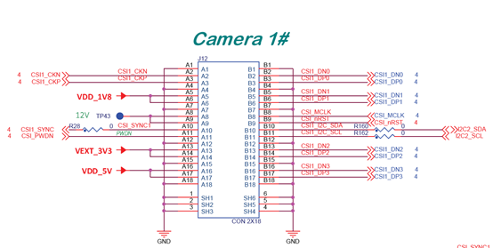
Refer to the imx8mp evk baseboard schematic, we can find camera 1# and camera 2# share the same reset and power down pins


Refer to the schematic, current evk uses gpio2_IO11 as power down pin and gpio1_IO06 as reset pin, but let’s see the i.mx8mp-evk.dts file
ov5640_1: ov5640_mipi@3c {
compatible = "ovti,ov5640";
reg = <0x3c>;
pinctrl-names = "default";
pinctrl-0 = <&pinctrl_csi0_pwn>, <&pinctrl_csi0_rst>, <&pinctrl_csi_mclk>;
clocks = <&clk IMX8MP_CLK_IPP_DO_CLKO2>;
clock-names = "xclk";
assigned-clocks = <&clk IMX8MP_CLK_IPP_DO_CLKO2>;
assigned-clock-parents = <&clk IMX8MP_CLK_24M>;
assigned-clock-rates = <24000000>;
csi_id = <0>;
powerdown-gpios = <&gpio4 1 GPIO_ACTIVE_HIGH>;
reset-gpios = <&gpio4 0 GPIO_ACTIVE_LOW>;
mclk = <24000000>;
mclk_source = <0>;
mipi_csi;
status = "disabled";
port {
ov5640_mipi_1_ep: endpoint {
remote-endpoint = <&mipi_csi1_ep>;
data-lanes = <1 2>;
clock-lanes = <0>;
};
};
};
So if customer wants connect I2C3 to ov5640, don’t forget change the power down pin and reset pin as what schematic defines
Then you can find the issue obviously in this dts file, and pls try to correct as below:
&i2c3 {
/delete-node/ov2775_mipi@36;
};
&ov5640_1 {
- pinctrl-0 = <&pinctrl_csi1_pwn>, <&pinctrl_csi1_rst>, <&pinctrl_csi_mclk>;
+ powerdown-gpios = <&gpio2 11 GPIO_ACTIVE_HIGH>;
+ reset-gpios = <&gpio1 6 GPIO_ACTIVE_LOW>;
csi_id = <1>;
status = "okay";
};
That’s why some customers tested ov5640 by imx8mp-evk-ov2775-ov5640.dts file failed
- Dual ov5640
Because ov5640 has ISP, so current bsp connect ov5640 by ISI, so customer can set status of &isi_0 or &isi_1 to “Okay” in the dts file if you just connect one ov5640, Because of evk HW limitation, current board couldn’t support dual ISI, which mean couldn't support dual ov5640, because they share the same power down pin and reset pin, so customer only can connect ov5640 by ISI0 or ISI1 to test