
- Forums
- Product Forums
- General Purpose MicrocontrollersGeneral Purpose Microcontrollers
- i.MX Forumsi.MX Forums
- QorIQ Processing PlatformsQorIQ Processing Platforms
- Identification and SecurityIdentification and Security
- Power ManagementPower Management
- Wireless ConnectivityWireless Connectivity
- RFID / NFCRFID / NFC
- Advanced AnalogAdvanced Analog
- Neural Processing UnitsNeural Processing Units
- MCX Microcontrollers
- S32G
- S32K
- S32V
- MPC5xxx
- Other NXP Products
- S12 / MagniV Microcontrollers
- Powertrain and Electrification Analog Drivers
- Sensors
- Vybrid Processors
- Digital Signal Controllers
- 8-bit Microcontrollers
- ColdFire/68K Microcontrollers and Processors
- PowerQUICC Processors
- OSBDM and TBDML
- S32M
- S32Z/E
-
- Solution Forums
- Software Forums
- MCUXpresso Software and ToolsMCUXpresso Software and Tools
- CodeWarriorCodeWarrior
- MQX Software SolutionsMQX Software Solutions
- Model-Based Design Toolbox (MBDT)Model-Based Design Toolbox (MBDT)
- FreeMASTER
- eIQ Machine Learning Software
- Embedded Software and Tools Clinic
- S32 SDK
- S32 Design Studio
- GUI Guider
- Zephyr Project
- Voice Technology
- Application Software Packs
- Secure Provisioning SDK (SPSDK)
- Processor Expert Software
- Generative AI & LLMs
-
- Topics
- Mobile Robotics - Drones and RoversMobile Robotics - Drones and Rovers
- NXP Training ContentNXP Training Content
- University ProgramsUniversity Programs
- Rapid IoT
- NXP Designs
- SafeAssure-Community
- OSS Security & Maintenance
- Using Our Community
-
- Cloud Lab Forums
-
- Knowledge Bases
- ARM Microcontrollers
- i.MX Processors
- Identification and Security
- Model-Based Design Toolbox (MBDT)
- QorIQ Processing Platforms
- S32 Automotive Processing Platform
- Wireless Connectivity
- CodeWarrior
- MCUXpresso Suite of Software and Tools
- MQX Software Solutions
- RFID / NFC
- Advanced Analog
- Neural Processing Units
-
- NXP Tech Blogs
Wire diagram for the TRK-MPC5604B
Wire diagram for the TRK-MPC5604B
Connection Diagram for TRK-MPC5604B to Rev. 1 Motor Control "Shield" Board

Connection Diagram for TRK-MPC5604B to Rev. 0 Motor Control Board 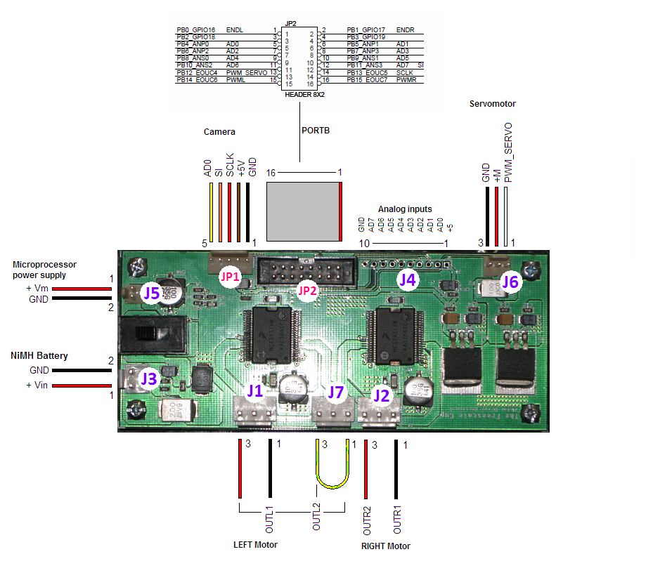
For the TRK-MPC5604, connect the flat ribbon cable to PortB as seen in the picture below.
Make the cable connections as shown below for dual motor with independent drive
connection

Make the cable connections as shown below for dual motor with series drive connection

Make the cable connections as shown below for Single motor connection

Protect your electronics
1. Try not to stop the wheels while in motion. This can cause current spikes.
2. Don’t disconnect or connect any cable when board is powered [ON].
3. Don’t discharge the battery below 5.5V
4. Don’t hit stationary objects :smileyhappy:
The links to various images on this article is broken. Can we please have them fixed? Thanks.
What mean ENDL and ENDR???
Are the pins for activate the left dc motor( ENDL ) and activate the right dc motor (ENDR), if this is true, then the PWML and PWMR are the inputs pins for the input PWM signal for each dc motor respectively ????
greetings...