
- Forums
- Product Forums
- General Purpose MicrocontrollersGeneral Purpose Microcontrollers
- i.MX Forumsi.MX Forums
- QorIQ Processing PlatformsQorIQ Processing Platforms
- Identification and SecurityIdentification and Security
- Power ManagementPower Management
- Wireless ConnectivityWireless Connectivity
- RFID / NFCRFID / NFC
- Advanced AnalogAdvanced Analog
- Neural Processing UnitsNeural Processing Units
- MCX Microcontrollers
- S32G
- S32K
- S32V
- MPC5xxx
- Other NXP Products
- S12 / MagniV Microcontrollers
- Powertrain and Electrification Analog Drivers
- Sensors
- Vybrid Processors
- Digital Signal Controllers
- 8-bit Microcontrollers
- ColdFire/68K Microcontrollers and Processors
- PowerQUICC Processors
- OSBDM and TBDML
- S32M
- S32Z/E
-
- Solution Forums
- Software Forums
- MCUXpresso Software and ToolsMCUXpresso Software and Tools
- CodeWarriorCodeWarrior
- MQX Software SolutionsMQX Software Solutions
- Model-Based Design Toolbox (MBDT)Model-Based Design Toolbox (MBDT)
- FreeMASTER
- eIQ Machine Learning Software
- Embedded Software and Tools Clinic
- S32 SDK
- S32 Design Studio
- GUI Guider
- Zephyr Project
- Voice Technology
- Application Software Packs
- Secure Provisioning SDK (SPSDK)
- Processor Expert Software
- Generative AI & LLMs
-
- Topics
- Mobile Robotics - Drones and RoversMobile Robotics - Drones and Rovers
- NXP Training ContentNXP Training Content
- University ProgramsUniversity Programs
- Rapid IoT
- NXP Designs
- SafeAssure-Community
- OSS Security & Maintenance
- Using Our Community
-
- Cloud Lab Forums
-
- Knowledge Bases
- ARM Microcontrollers
- i.MX Processors
- Identification and Security
- Model-Based Design Toolbox (MBDT)
- QorIQ Processing Platforms
- S32 Automotive Processing Platform
- Wireless Connectivity
- CodeWarrior
- MCUXpresso Suite of Software and Tools
- MQX Software Solutions
- RFID / NFC
- Advanced Analog
- Neural Processing Units
-
- NXP Tech Blogs
- Home
- :
- Product Forums
- :
- S32K
- :
- No activity on MOSI and CS with example code on S32K344
No activity on MOSI and CS with example code on S32K344
- Subscribe to RSS Feed
- Mark Topic as New
- Mark Topic as Read
- Float this Topic for Current User
- Bookmark
- Subscribe
- Mute
- Printer Friendly Page
- Mark as New
- Bookmark
- Subscribe
- Mute
- Subscribe to RSS Feed
- Permalink
- Report Inappropriate Content
Hello,
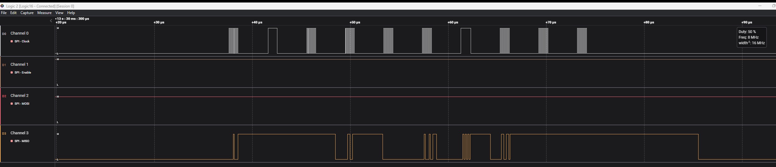
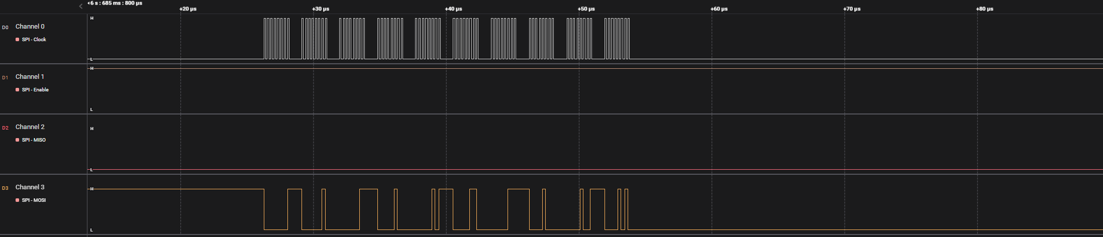
I am unable to get the example code with LPSPI4 as the master (on NxP S32K344 - MR-CANHUB) and Aardvark SPI adapter as the slave. The baudrate is configured as 8Mhz. Clock measurement on Saleae does show that as 8 Mhz.
I have tried all possible configurations to make sure that CS and MOSI show some activity. However, I am unable to get it to work.
See attached snapshot of saleae. Also code is attached.
This is on FreeRTOS with RTD drivers.
Solved! Go to Solution.
- Mark as New
- Bookmark
- Subscribe
- Mute
- Subscribe to RSS Feed
- Permalink
- Report Inappropriate Content
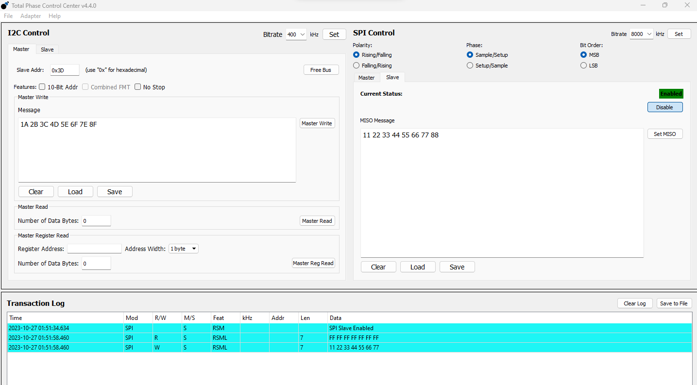
I made some modifications to your code and the test results are as follows.

Your pin configuration is wrong and I lowered the communication rate so that I can test.
- Mark as New
- Bookmark
- Subscribe
- Mute
- Subscribe to RSS Feed
- Permalink
- Report Inappropriate Content
- Mark as New
- Bookmark
- Subscribe
- Mute
- Subscribe to RSS Feed
- Permalink
- Report Inappropriate Content
Thanks Senlet. After making the pin configuration change, I see that CS is always low (and is not toggling). Also for me MOSI is always HIGH. In your case, it is all 0's. I am trying to send the following data over MOSI lines - {1, 2, ..., 10}. I dont see that on MOSI.
And I am unable to change the FreeRTOS clock to 120000000. Is that necessary for LPSPI to work properly?
I am attaching my changes.
- Mark as New
- Bookmark
- Subscribe
- Mute
- Subscribe to RSS Feed
- Permalink
- Report Inappropriate Content
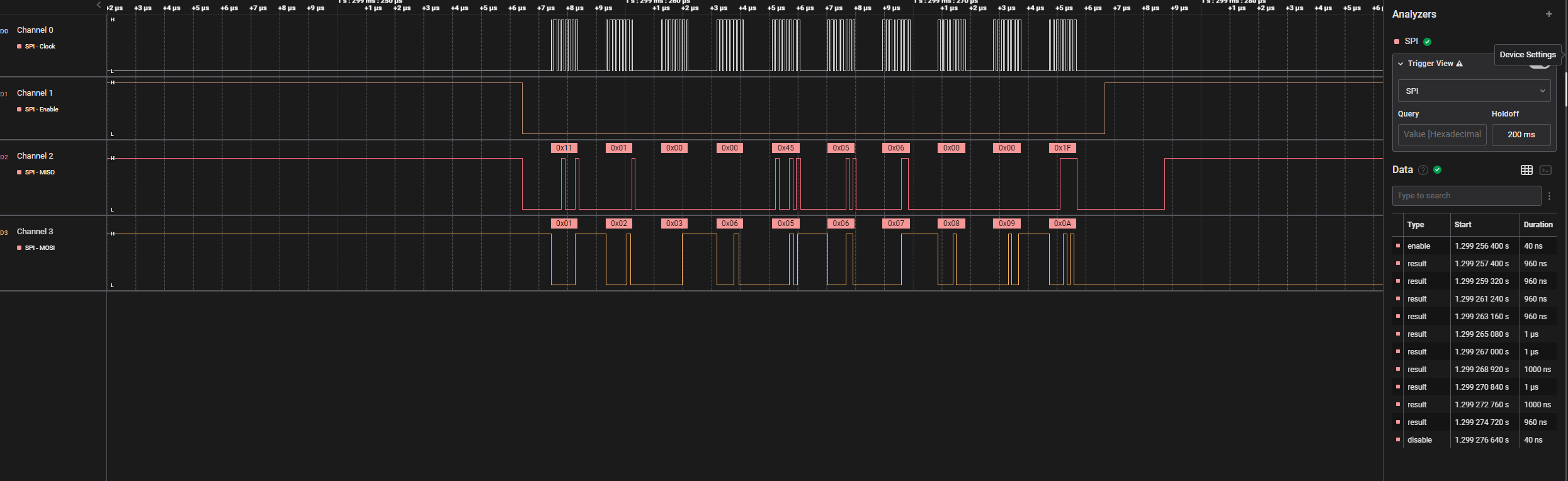
This is the demo you provided and I have not made any modifications .
The test results are as follows:

You can see that as the master side, the data sent by the MCU is normal, and the MOSI should be controlled by the slave side, if there is no data, I think you should fine the problem on the slave side.
In addition, the above test hardware is based on the mini-board, and all IO ports are directly connected to the logic analyzer.
- Mark as New
- Bookmark
- Subscribe
- Mute
- Subscribe to RSS Feed
- Permalink
- Report Inappropriate Content
You mean MISO should be controlled by the slave.
It is unfortunate that the schematic of the MRCANHUB board refers to SIN as MOSI and SOUT as MISO. However, S32K pins refer to SIN as input and SOUT as output. This has caused a lot of confusion on my side.
This is what my understanding is regarding SIN and SOUT? Please correct me, if that is wrong:
SIN - Input to the SPI entity (master or slave)
SOUT - Output from the SPI entity (master or slave)
So, if S32K344 acts as the Master, SIN should be connected to SOUT of the slave, which means it acts as MISO on the master side.
Similarly, SOUT of the S32K344 should be connected to the SIN of the slave, which means S32K's SOUT pin acts as MOSI.
Finally, for some reason - I either see CS being low or high all the time even when I have the setting to be CS_TOGGLE instead of CS_KEEP_ASSERTED. And in both scenarios S32K is able to communicate with the slave.
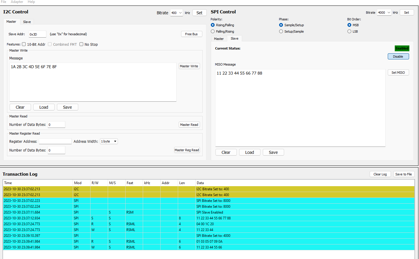
Also, with the SPI_DATA_WIDTH set to 8 bits, I see the that at 8Khz, S32K as a master spits out only 4 bytes to which the slave responds by sending 4 bytes.
However, at 4Khz more than 4 bytes are sent out (for example 7 bytes) and the slave responds with the same number of bytes.
- Mark as New
- Bookmark
- Subscribe
- Mute
- Subscribe to RSS Feed
- Permalink
- Report Inappropriate Content
1.very easy to understanding,


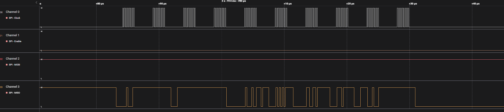
2.From the screenshot I sent you, you can see that the CS pin works exactly as expected.
If your CS pin has not changed, I think you can check the hardware of this pin.
What I can help you do is troubleshoot your software problems. I can't help you troubleshoot other problems. We don't have CANHUB hardware.
- Mark as New
- Bookmark
- Subscribe
- Mute
- Subscribe to RSS Feed
- Permalink
- Report Inappropriate Content
I made some modifications to your code and the test results are as follows.
Your pin configuration is wrong and I lowered the communication rate so that I can test.