- Forums
- Product Forums
- General Purpose MicrocontrollersGeneral Purpose Microcontrollers
- i.MX Forumsi.MX Forums
- QorIQ Processing PlatformsQorIQ Processing Platforms
- Identification and SecurityIdentification and Security
- Power ManagementPower Management
- Wireless ConnectivityWireless Connectivity
- RFID / NFCRFID / NFC
- MCX Microcontrollers
- S32G
- S32K
- S32V
- MPC5xxx
- Other NXP Products
- S12 / MagniV Microcontrollers
- Powertrain and Electrification Analog Drivers
- Sensors
- Vybrid Processors
- Digital Signal Controllers
- 8-bit Microcontrollers
- ColdFire/68K Microcontrollers and Processors
- PowerQUICC Processors
- OSBDM and TBDML
- S32M
-
- Solution Forums
- Software Forums
- MCUXpresso Software and ToolsMCUXpresso Software and Tools
- CodeWarriorCodeWarrior
- MQX Software SolutionsMQX Software Solutions
- Model-Based Design Toolbox (MBDT)Model-Based Design Toolbox (MBDT)
- FreeMASTER
- eIQ Machine Learning Software
- Embedded Software and Tools Clinic
- S32 SDK
- S32 Design Studio
- GUI Guider
- Zephyr Project
- Voice Technology
- Application Software Packs
- Secure Provisioning SDK (SPSDK)
- Processor Expert Software
-
- Topics
- Mobile Robotics - Drones and RoversMobile Robotics - Drones and Rovers
- NXP Training ContentNXP Training Content
- University ProgramsUniversity Programs
- Rapid IoT
- NXP Designs
- SafeAssure-Community
- OSS Security & Maintenance
- Using Our Community
-
- Cloud Lab Forums
-
- Knowledge Bases
- ARM Microcontrollers
- i.MX Processors
- Identification and Security
- Model-Based Design Toolbox (MBDT)
- QorIQ Processing Platforms
- S32 Automotive Processing Platform
- Wireless Connectivity
- CodeWarrior
- MCUXpresso Suite of Software and Tools
- MQX Software Solutions
- RFID / NFC
-
- Home
- :
- Product Forums
- :
- S32K
- :
- Duration count value of IPWM in S32K3
Duration count value of IPWM in S32K3
- Subscribe to RSS Feed
- Mark Topic as New
- Mark Topic as Read
- Float this Topic for Current User
- Bookmark
- Subscribe
- Mute
- Printer Friendly Page
- Mark as New
- Bookmark
- Subscribe
- Mute
- Subscribe to RSS Feed
- Permalink
- Report Inappropriate Content
Could you tell me why ActiveTime of IPWM is not understand value.
Below pic is my result when detect PWM signal that are each 1/1000, 250/1000, 500/1000, 750/1000, 999/1000 PWM signal.
Reference code is same as https://community.nxp.com/t5/S32K/S32K344-MCAL-IPWM-ICU-CAPTURE/m-p/1541889 example.
MCU is S32K312 and SDK is PlatformSDK_S32K3_2022_07_S32K312_M7 Ver 2.0.1.
The ration of ActiveTime is not understand each PWM duration.
Solved! Go to Solution.
- Mark as New
- Bookmark
- Subscribe
- Mute
- Subscribe to RSS Feed
- Permalink
- Report Inappropriate Content
Hello @dnewbe,
I'm sorry for the delay.
I made some changes in the project, and it works right now, plase find the modified project attached.
The main change was the edge polarity of the EMIOS IPWM channel.
It can't be set in the configuration tool of the ICU driver, so I set it by a direct write to the register in main().
IP_EMIOS_1->CH.UC[1].C |= eMIOS_C_EDPOL(1);
Overflow is an even when the MCL EMIOS_0_MasteBus0 overflows from 65535 to 0.
Regards,
Daniel
- Mark as New
- Bookmark
- Subscribe
- Mute
- Subscribe to RSS Feed
- Permalink
- Report Inappropriate Content
I modify for your answer and I got wanted result.
My log of result is
PWM duty (1), period (1061)
Bright Level (0)
PWM duty (319), period (1061)
Bright Level (30)
PWM duty (637), period (1061)
Bright Level (60)
PWM duty (1060), period (1061)
Bright Level (100)
Thanks danielmartynek.
- Mark as New
- Bookmark
- Subscribe
- Mute
- Subscribe to RSS Feed
- Permalink
- Report Inappropriate Content
Hello @dnewbe,
There are two projects in the thread that you linked.
I don't knonw which one you use and what changes you made in it since then.
Can you share the project you have right now?
Double-check the EMIOs clock that the IPWM uses, it is possible that the counter overflows?
What is the period in which the counter overflows and what is the period of the PWM signal?
Thank you,
BR, Daniel
- Mark as New
- Bookmark
- Subscribe
- Mute
- Subscribe to RSS Feed
- Permalink
- Report Inappropriate Content
- Mark as New
- Bookmark
- Subscribe
- Mute
- Subscribe to RSS Feed
- Permalink
- Report Inappropriate Content
Hello @dnewbe,
Thank you for the project, but I can't open the .mex file of the project.
Which RTD version do you use?
Can you use the latest version?
BR, Daniel
- Mark as New
- Bookmark
- Subscribe
- Mute
- Subscribe to RSS Feed
- Permalink
- Report Inappropriate Content
Hello @dnewbe,
Could you increase the period of EMIOS_ICU_BUS_A in the MCL driver from the 1 you selected?
So that the counter does not everflow?
Thank you,
Daniel
- Mark as New
- Bookmark
- Subscribe
- Mute
- Subscribe to RSS Feed
- Permalink
- Report Inappropriate Content
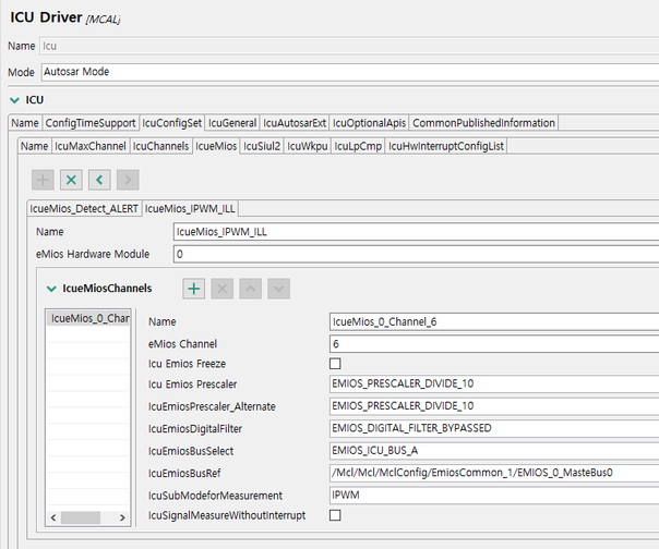
Capture image of my setting is below.
The result is not change when each Prescaler and Alternate is DIVIDE_1.
And tell me overflow is what and how do I check ?
Test I did
my board run 160 MHz is count PWM signal.
other board generate PWM signal each 1, 25, 50, 75, 99 duty of 1 KHz.
- Mark as New
- Bookmark
- Subscribe
- Mute
- Subscribe to RSS Feed
- Permalink
- Report Inappropriate Content
Hello @dnewbe,
I'm sorry for the delay.
I made some changes in the project, and it works right now, plase find the modified project attached.
The main change was the edge polarity of the EMIOS IPWM channel.
It can't be set in the configuration tool of the ICU driver, so I set it by a direct write to the register in main().
IP_EMIOS_1->CH.UC[1].C |= eMIOS_C_EDPOL(1);
Overflow is an even when the MCL EMIOS_0_MasteBus0 overflows from 65535 to 0.
Regards,
Daniel


