
- Forums
- Product Forums
- General Purpose MicrocontrollersGeneral Purpose Microcontrollers
- i.MX Forumsi.MX Forums
- QorIQ Processing PlatformsQorIQ Processing Platforms
- Identification and SecurityIdentification and Security
- Power ManagementPower Management
- Wireless ConnectivityWireless Connectivity
- RFID / NFCRFID / NFC
- Advanced AnalogAdvanced Analog
- Neural Processing UnitsNeural Processing Units
- MCX Microcontrollers
- S32G
- S32K
- S32V
- MPC5xxx
- Other NXP Products
- S12 / MagniV Microcontrollers
- Powertrain and Electrification Analog Drivers
- Sensors
- Vybrid Processors
- Digital Signal Controllers
- 8-bit Microcontrollers
- ColdFire/68K Microcontrollers and Processors
- PowerQUICC Processors
- OSBDM and TBDML
- S32M
- S32Z/E
-
- Solution Forums
- Software Forums
- MCUXpresso Software and ToolsMCUXpresso Software and Tools
- CodeWarriorCodeWarrior
- MQX Software SolutionsMQX Software Solutions
- Model-Based Design Toolbox (MBDT)Model-Based Design Toolbox (MBDT)
- FreeMASTER
- eIQ Machine Learning Software
- Embedded Software and Tools Clinic
- S32 SDK
- S32 Design Studio
- GUI Guider
- Zephyr Project
- Voice Technology
- Application Software Packs
- Secure Provisioning SDK (SPSDK)
- Processor Expert Software
- Generative AI & LLMs
-
- Topics
- Mobile Robotics - Drones and RoversMobile Robotics - Drones and Rovers
- NXP Training ContentNXP Training Content
- University ProgramsUniversity Programs
- Rapid IoT
- NXP Designs
- SafeAssure-Community
- OSS Security & Maintenance
- Using Our Community
-
- Cloud Lab Forums
-
- Knowledge Bases
- ARM Microcontrollers
- i.MX Processors
- Identification and Security
- Model-Based Design Toolbox (MBDT)
- QorIQ Processing Platforms
- S32 Automotive Processing Platform
- Wireless Connectivity
- CodeWarrior
- MCUXpresso Suite of Software and Tools
- MQX Software Solutions
- RFID / NFC
- Advanced Analog
- Neural Processing Units
-
- NXP Tech Blogs
- Home
- :
- パワーマネージメント
- :
- パワーマネージメント
- :
- Re: KITPF8200FRDMPGM OTP Voltage Issue
KITPF8200FRDMPGM OTP Voltage Issue
- RSS フィードを購読する
- トピックを新着としてマーク
- トピックを既読としてマーク
- このトピックを現在のユーザーにフロートします
- ブックマーク
- 購読
- ミュート
- 印刷用ページ
KITPF8200FRDMPGM OTP Voltage Issue

- 新着としてマーク
- ブックマーク
- 購読
- ミュート
- RSS フィードを購読する
- ハイライト
- 印刷
- 不適切なコンテンツを報告
Hi All,
We have a KITPF8200FRDMPGM connected to a FRDM-KL25Z and are investigating if the PF8121 can be burnt (OTP) on a KITPF8121FRDMEVM.
The programmer communicates with a PC running Flex GUI 1.21 and the FRDMEVM board can be configured for testing.
Measuring the voltage on the pin 4 on J15 (OTP) of the KITPF8200FRDMPGM while running the Script Editor in FlexGUI gives 4.8 V then returns to 0 V. This should be approx. 7.5 V.
Example script.
//Device: PF8121
//Generated by PF8xxx GUI
SET_DPIN:PF8121:TBBEN:high
SET_DPIN:PF8121:STANDBY:low
SET_DPIN:PF8121:WDI:low
SET_DPIN:PF8121:PWRON:low
SET_DPIN:PF8121:VDDOTPEN:high
....
There are no devices plugged into J15 or into the programming socket of the PGM board.
Any ideas on what we can verify next?
Regards
Greg

 TomasVaverka
- 新着としてマーク
- ブックマーク
- 購読
- ミュート
- RSS フィードを購読する
- ハイライト
- 印刷
- 不適切なコンテンツを報告
Hi Greg,
KITPF8200FRDMPGM can be used to burn OTP file for PF81xx and PF82xx. Do you want to burn OTP file on the KITPF8121FRMEVM instead of KITPF8200FRDMPGM?
If yes, there is no 8V boost converter circuitry on the KITPF8121FRMEVM board to supply 8V power to VDDOTP pin. So when user burns OTP on the KITPF8121FRMEVM board, user needs to connect external 8V power supply to J20 pin2 of KITPF8121FRMEVM.
Best regards,
Tomas
- 新着としてマーク
- ブックマーク
- 購読
- ミュート
- RSS フィードを購読する
- ハイライト
- 印刷
- 不適切なコンテンツを報告
Hi Tomas,
Thanks for the reply.
We would like to burn the KITPF8121FRDMEVM using the KITPF8200FRDMPGM.
This is a step prior to burning our development systems which use a pair of PF8121's.
If we connect the KITPF8200FRDMPGM to a PC running FlexGUI, then run the ScriptEditor, the KITPF8200FRDMPGM does not output 7.5 V as specified. The boost (LCD driver) on the KITPF8200FRDMPGM appears to have UP and DOWN pins to adjust the voltage. How are these configured by the FlexGUI if at all?
The MOSFET gate which enables the OTP output voltage is driven from the FRDM-KL25Z with approx 3.28 V, so this looks correct.
Is there anything left to check on KITPF8200FRDMPGM?
Regards
Greg
TomasVaverka
- 新着としてマーク
- ブックマーク
- 購読
- ミュート
- RSS フィードを購読する
- ハイライト
- 印刷
- 不適切なコンテンツを報告
Hi Greg,
I am not sure I understand what you are trying to do.
We offer the PF8200/PF8100 Programming Board: KITPF8200FRDMPGM which is used to burn OTP of Blank PF82, notice OTP is one time programmable. For more information please refer to the UM11162.
If you do not have the programming board or you solder Blank version on the board, you can still use the KL25FRDM board to operate the OTP burn process by the PF82 Flex GUI to solve some urgent cases.
The connection structure is:
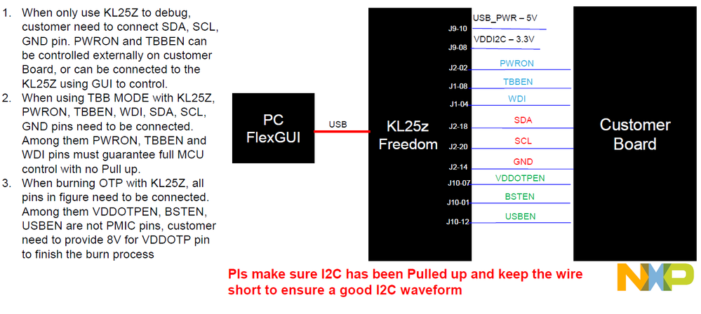
One 8V voltage from external supply for VDDOTP is needed and then run the script which is generated from OTP Excel file. If other pins are connected properly, the OTP burn can be achieved by this way on customers' board.
You can also develop the OTP burn tool by yourselves on your hardware product line, the code and operation process can refer to the script which is generated from the OTP request form.
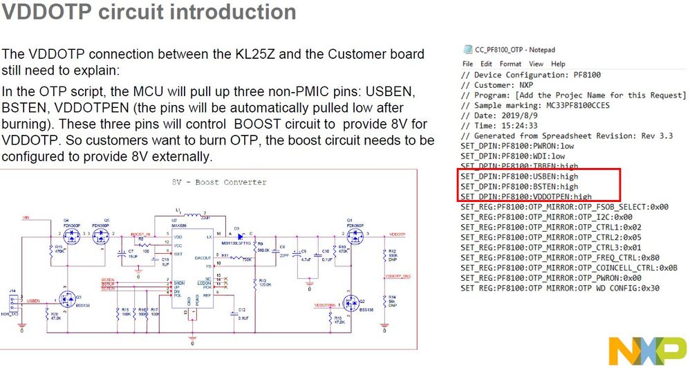
I hope t helps.
Best regards,
Tomas
- 新着としてマーク
- ブックマーク
- 購読
- ミュート
- RSS フィードを購読する
- ハイライト
- 印刷
- 不適切なコンテンツを報告
Hi Tomas
Appreciate the detailed reply you have provided.
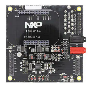
The KITPF8121FRDMEVM contains the A0 variant of the PF8121. This is the unprogrammed version of the device in the family which we would like to burn OTP. The board breaks out the VDDOTP to a jumper so this looks possible.
Replacing a wrongly programmed PF8121 from the KITPF8121FRDMEVM carries far less risk than the performing the same work on our prototype 14 layer boards containing a pair of PF8121's.
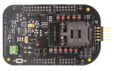

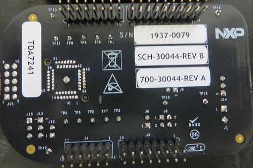

We believe our NXP hardware may be faulty and a trying to verify. So, using only the KITPF8200FRDMPGM with a KL25 connected to FlexGUI, the boost converter should provide 7.5 - 8 V when running the script as shown in your previous email. However the KITPF8200FRDMPGM provides approximately 5 V when the VDDOTPEN line is enabled in the FlexGUI. When the script disables VDDOTPEN line the voltage drops to near 0 V. The OTP line is unconnected to any load.
Is there any diagnostic information which can be provided to determine if this is an issue with the KITPF8200FRDMPGM or the KL25?
There are other signals interfacing between the KL25 and the driver (MAX686) on the KITPF8200FRDMPGM. What states should these pins be in?
Appreciate any information you can provide.
Regards
Greg
TomasVaverka
- 新着としてマーク
- ブックマーク
- 購読
- ミュート
- RSS フィードを購読する
- ハイライト
- 印刷
- 不適切なコンテンツを報告
Hi Greg,
It sounds like there is indeed a problem with the boost circuit. Please connect an external 8V power supply and delete the boost enable script.
Best regards,
Tomas
- 新着としてマーク
- ブックマーク
- 購読
- ミュート
- RSS フィードを購読する
- ハイライト
- 印刷
- 不適切なコンテンツを報告
Hi Tomas
Found the issue in the script, the boost was not being activated.
SET_DPIN:PF8121:TBBEN:high
SET_DPIN:PF8121:USBEN:high
SET_DPIN:PF8121:BSTEN:high
SET_DPIN:PF8121:STANDBY:low
SET_DPIN:PF8121:VDDOTPEN:high
Thanks for your help with this!
Regards
Greg
