
- Forums
- Product Forums
- General Purpose MicrocontrollersGeneral Purpose Microcontrollers
- i.MX Forumsi.MX Forums
- QorIQ Processing PlatformsQorIQ Processing Platforms
- Identification and SecurityIdentification and Security
- Power ManagementPower Management
- Wireless ConnectivityWireless Connectivity
- RFID / NFCRFID / NFC
- Advanced AnalogAdvanced Analog
- Neural Processing UnitsNeural Processing Units
- MCX Microcontrollers
- S32G
- S32K
- S32V
- MPC5xxx
- Other NXP Products
- S12 / MagniV Microcontrollers
- Powertrain and Electrification Analog Drivers
- Sensors
- Vybrid Processors
- Digital Signal Controllers
- 8-bit Microcontrollers
- ColdFire/68K Microcontrollers and Processors
- PowerQUICC Processors
- OSBDM and TBDML
- S32M
- S32Z/E
-
- Solution Forums
- Software Forums
- MCUXpresso Software and ToolsMCUXpresso Software and Tools
- CodeWarriorCodeWarrior
- MQX Software SolutionsMQX Software Solutions
- Model-Based Design Toolbox (MBDT)Model-Based Design Toolbox (MBDT)
- FreeMASTER
- eIQ Machine Learning Software
- Embedded Software and Tools Clinic
- S32 SDK
- S32 Design Studio
- GUI Guider
- Zephyr Project
- Voice Technology
- Application Software Packs
- Secure Provisioning SDK (SPSDK)
- Processor Expert Software
- Generative AI & LLMs
-
- Topics
- Mobile Robotics - Drones and RoversMobile Robotics - Drones and Rovers
- NXP Training ContentNXP Training Content
- University ProgramsUniversity Programs
- Rapid IoT
- NXP Designs
- SafeAssure-Community
- OSS Security & Maintenance
- Using Our Community
-
- Cloud Lab Forums
-
- Knowledge Bases
- ARM Microcontrollers
- i.MX Processors
- Identification and Security
- Model-Based Design Toolbox (MBDT)
- QorIQ Processing Platforms
- S32 Automotive Processing Platform
- Wireless Connectivity
- CodeWarrior
- MCUXpresso Suite of Software and Tools
- MQX Software Solutions
- RFID / NFC
- Advanced Analog
- Neural Processing Units
-
- NXP Tech Blogs
- Home
- :
- Product Forums
- :
- Other NXP Products
- :
- Re: False Tamper detection occasionally
False Tamper detection occasionally
- Subscribe to RSS Feed
- Mark Topic as New
- Mark Topic as Read
- Float this Topic for Current User
- Bookmark
- Subscribe
- Mute
- Printer Friendly Page
False Tamper detection occasionally

- Mark as New
- Bookmark
- Subscribe
- Mute
- Subscribe to RSS Feed
- Permalink
- Report Inappropriate Content
We have used IC : PCA2129T in one of our custom board design.
The schematic of the same is enclosed here, for reference.
Battery used is CR2032 Panasonic, 3.0V. We have used the IC : PCA2129T for RTC time reading and Tamper detection. Battery voltage measured in problematic sets is more than 2.8 V.
PCA2129T is being used in standard mode (as default).
However, Tamper detection is not working reliably. Occasionally false Tamer detection is happening. Note: TSF1 and TSF2 bit is being read for Tamper detection in our design. (Interrupt line is not being used due to Hardware constraint.)
Also, Sometimes RTC time reading displays incorrect value in Seconds field, (Ex: sometime second field displays value upto 139 Sec !).
Kindly suggest what could be the issue. Kindly do the needful on priority.
Regards, Sanjay Kumar Singh,
 guoweisun
- Mark as New
- Bookmark
- Subscribe
- Mute
- Subscribe to RSS Feed
- Permalink
- Report Inappropriate Content
Hi
Some suggestion for your application:
1: You can’t use the direct switching mode because of VDD/VBAT voltage is similar.
2: In your schematic of C293 should be put as close as possible pin6 of RTC
3: AN11186 page13-5.4 Timestamp applications, I hope you can refer to it when you design the Timestamp function,honestly I don’t understand your schematic about this Timestamp function part.
4: AN11186 page18-5.9 Timekeeping, CLKOUT, power management and timestamp,I suppose your application is similar this example,if yes can you refer to it?
You can download the AN11186 from below link:
AN11186 Application and soldering information for the PCA2129 and PCF2129 TCXO RTC (nxp.com.cn)
- Mark as New
- Bookmark
- Subscribe
- Mute
- Subscribe to RSS Feed
- Permalink
- Report Inappropriate Content
Hi, Thank you for your reply.
1. we are using standard mode. PWRMNG[2:0] is set to "000" as default value. Hence Standard mode gets selected.
2. C293 is placed near pin6 of RTC.
3. AN11186 page13-5.4 is having two Tamper switches(SW1 and SW2) and an external resistor ( R2) 220KiloOhm.
But in our Schematic:
only one Tamper switch(SW1) is placed. R2 is 0 ohm.
a. Voltage at TS signal (pin-6) is 0 Volt if Tamper switch (SW1) Open (Equipment Cover is opened/removed).
b. Voltage at TS signal (pin-6) is 3 Volt if Tamper switch (SW1) closed (Equipment Cover is placed/closed).
Note: we are not reading the Timestamp resistors of PCA2129T and not using the interrupt (INT-pin13). Tamper detection is being done based on TSF1 and TSF2 being read every second.
c. In our application PCA2129T is being used only for two purposes : Tamper detection and RTC Time reading.
Q1. Can you provide an Application note of PCA2129T where only one Tamper switch (SW1) is used ?
Q2. Please suggest if only one Tamper switch (SW1) is used then what should be the value of Resistor R2 in AN11186 page13-5.4 ?
Q3. Please provide the Sequence of initialisation, which has to be done during Power ON for PCA2129T being used for Tamper detection and RTC Time reading only ?
Q4. Please provide Sequence of operations to be carried out for Tamper detection ?
Q5. Please provide the sequence of resistors to be written and read for amper detection and RTC Time reading only ?
Q6. Whether Tamper detection has to be done based on both TSF1 and TSF2 in our case ?
Q7. Under what conditions PCA2129T may give false tamper ?
4. AN11186 page18-5.9 is referred but Cause of Tamper detection is unclear.
guoweisun
- Mark as New
- Bookmark
- Subscribe
- Mute
- Subscribe to RSS Feed
- Permalink
- Report Inappropriate Content
Q1. Can you provide an Application note of PCA2129T where only one Tamper switch (SW1) is used ?
[gw]I copy in the datasheet below,you can see that if you use only one tramper switch for example condition2 below descript, once trigger timestamp both the TSF1 and TSF2 are set. :
---
Timestamp flag
1. When the TS input pin is driven to an intermediate level between the power supply and ground, either on the falling edge from VDD or on the rising edge from ground, then the following sequence occurs:
a. The actual date and time are stored in the timestamp registers.
b. The timestamp flag TSF1 (register Control_1) is set.
c. If the TSIE bit (register Control_2) is active, an interrupt on the INT pin is generated. The TSF1 flag can be cleared by command. Clearing the flag clears the interrupt. Once TSF1 is cleared, it will only be set again when a new negative or positive edge on pin TS is detected.
2. When the TS input pin is driven to ground, the following sequence occurs:
a. The actual date and time are stored in the timestamp registers.
b. In addition to the TSF1 flag, the TSF2 flag (register Control_2) is set.
c. If the TSIE bit is active, an interrupt on the INT pin is generated. The TSF1 and TSF2 flags can be cleared by command; clearing both flags clears the interrupt. Once TSF2 is cleared, it will only be set again when TS pin is driven to ground once again.
---
Q2. Please suggest if only one Tamper switch (SW1) is used then what should be the value of Resistor R2 in AN11186 page13-5.4 ?
[gw]same with Q1,for example if you select condition2,no need R2. If select condition1 you can series in 220K R2.
Q3. Please provide the Sequence of initialisation, which has to be done during Power ON for PCA2129T being used for Tamper detection and RTC Time reading only ?
[gw] You can see UM10762 page14- 5. Software for more.
You can download it from below:
Q4. Please provide Sequence of operations to be carried out for Tamper detection ?
[gw] The timestamp function is enabled by default after power-on,you can set the TSIE bit once timestamp trigger, an interrupt on the INT pin is generated and you can read the actual date and time in the timestamp registers.
Q5. Please provide the sequence of resistors to be written and read for tamper detection and RTC Time reading only ?
[gw]same with Q4.
Q6. Whether Tamper detection has to be done based on both TSF1 and TSF2 in our case ? [gw]Depend on your requirements.
Q7. Under what conditions PCA2129T may give false tamper ?
[gw]No guarantee,if you understand how to use this function normally no issue.
- Mark as New
- Bookmark
- Subscribe
- Mute
- Subscribe to RSS Feed
- Permalink
- Report Inappropriate Content
Dear G.W.
Thank you very much for your prompt response.
As per our Schematic
A). Only one Tamper switch (SW1) is used, Hence as mentioned by you 220KOhm resistance R2 is not required. Hence R161 and R162 is 0 Ohm in our Schematic.
Q.1. So, Please confirm that the Schematic is okay for Tamper detection and RTC time reading ?
B). Since only one switch SW1 is used, Hence 220KOhm resistance R2 is not required.
and Interrupt (INT) line is not used due to H/w constraint.
Q.2.a. So, as per datasheet (8.11.1) Only condition-2 can get generated. Condition-1 will never be generated, pls confirm ?
Q.2.b. Hence, Tamper detection status can be read by reading only TSF2 Flag of Control register-2 . Please confirm ?
Q.2.c. TSF1 Flag of Control register-1 should not be used for Tamper detection for our design. It will not be relevant for our design. Please confirm ?
C. On power-ON all the registers are having default values in our s/w implementation.Whether this is okay ?
Q.3.a. Do I need to clear OSF bit (Register-03h) in during Power ON or not ? Please suggest ?
Q.3.b. Since PCA2129T will have Power either from external source (3.3V at Pin-16) or from Battery (3.0V at Pin-15), So, PCA2129T will be powered-ON and work reliably for Tamper and RTC functionality till the time battery voltage is equal or above 2.5V. Please confirm ?
Q.3.c. Hence if OSF bit is set once during first time programming (after Battery is mounted), This should be sufficient and OSF bit need not be cleared every time during Power- ON and Power-OFF through external source(3.3V at Pin-16). Please confirm ?
D. As per the datasheet, The OTP refresh should be executed as the first instruction after start-up and also after a reset.
Q.4.a. what are the implications if OTP refresh not done ?
Q.4.b. Will it have any implication on false Tamper detection ?
Q.4.c. Will it have any implication on false time & date reading from RTC ?
Q.5. If the CLKOUT (at pin-7) is kept to default frequency of 32.768Khz, COF[2:0] =000 and AO[3:0], then will it have any implication on false Tamper detection ? Will it have any implication on false time & date reading from RTC ?
Q.6. What is meant by the statement (in datasheet) "Setting or reading seconds through to years should be made in one single access". Please explain in terms of I2C command sequence start and stop ?
Q.7. As per the datsheet : If the I2C bus communication was terminated uncontrolled, the I2C bus has to be reinitialised by sending a STOP followed by a START after the device switched back from battery backup operation to VDD supply operation. So,
Q.7a. If a I2C communication is initiated and could not complete due to MASTER device POWER-OFF (external power 0v at pin-16) then during next POWER-ON, whether MASTER device should initiate a I2C STOP command or can start as usual with a I2C START command ?
Q.7b. Will it have any implication on false Tamper detection ?
Q. 8. whether TSOFF bit should be cleared for Tamper detection and RTC time reading ?
Q.9. How much should be the Battery threshold voltage for Tamper detection and RTC time reading for our design ?
Q.10. Whether there is any timeout in the I2C communication from slave(PCA2129T) side ?
Q.11. Please find a waveform of a Master device communicating with PCA2129T, Kindly suggest whether multiple glitches seen in the waveform may lead to false Tamper detection ?
Thanking you for your support.

 guoweisun
- Mark as New
- Bookmark
- Subscribe
- Mute
- Subscribe to RSS Feed
- Permalink
- Report Inappropriate Content
A). Only one Tamper switch (SW1) is used, Hence as mentioned by you 220KOhm resistance R2 is not required. Hence R161 and R162 is 0 Ohm in our Schematic.
Q.1. So, Please confirm that the Schematic is okay for Tamper detection and RTC time reading ?
[gw]You can use one SW1 for example connect SW1 to TS pin then to ground. You can refer to below picture TS configuration to update your schematic then test again.
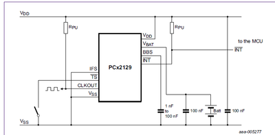
B). Since only one switch SW1 is used, Hence 220KOhm resistance R2 is not required.
and Interrupt (INT) line is not used due to H/w constraint.
Q.2.a. So, as per datasheet (8.11.1) Only condition-2 can get generated. Condition-1 will never be generated, pls confirm ?
[gw]Unless the TS input pin is driven to an intermediate level between the power supply and ground, either on the falling edge from VDD or on the rising edge from ground. This function still be active.
Q.2.b. Hence, Tamper detection status can be read by reading only TSF2 Flag of Control register-2 . Please confirm ?
[gw]No.
Q.2.c. TSF1 Flag of Control register-1 should not be used for Tamper detection for our design. It will not be relevant for our design. Please confirm ?
[gw]OK.
- On power-ON all the registers are having default values in our s/w implementation. Whether this is okay ?
[gw] Timestamp function default is active.
Q.3.a. Do I need to clear OSF bit (Register-03h) in during Power ON or not ? Please suggest ?
[gw]Yes,you can.
Q.3.b. Since PCA2129T will have Power either from external source (3.3V at Pin-16) or from Battery (3.0V at Pin-15), So, PCA2129T will be powered-ON and work reliably for Tamper and RTC functionality till the time battery voltage is equal or above 2.5V. Please confirm ?
[gw] Standard mode
If VDD > VBAT OR VDD > Vth(sw)bat: Voper(int) is at VDD potential.
If VDD < VBAT AND VDD < Vth(sw)bat: Voper(int) is at VBAT potential
When it works on VDD or Vbat potential the Tamper and RTC functionality works reliably.
Q.3.c. Hence if OSF bit is set once during first time programming (after Battery is mounted), This should be sufficient and OSF bit need not be cleared every time during Power- ON and Power-OFF through external source(3.3V at Pin-16). Please confirm ?
[gw]You should clear it each power on /off.
- As per the datasheet, The OTP refresh should be executed as the first instruction after start-up and also after a reset.
Q.4.a. what are the implications if OTP refresh not done ?
[gw]time accuracy will be affected.
Q.4.b. Will it have any implication on false Tamper detection ?
[gw]No
Q.4.c. Will it have any implication on false time & date reading from RTC ?
[gw]same with Q4a.
Q.5. If the CLKOUT (at pin-7) is kept to default frequency of 32.768Khz, COF[2:0] =000 and AO[3:0], then will it have any implication on false Tamper detection ? Will it have any implication on false time & date reading from RTC ?
[gw]No
Q.6. What is meant by the statement (in datasheet) "Setting or reading seconds through to years should be made in one single access". Please explain in terms of I2C command sequence start and stop ?
[gw] That is, setting or reading seconds through to years should be made in one single
Access.
Q.7. As per the datsheet : If the I2C bus communication was terminated uncontrolled, the I2C bus has to be reinitialised by sending a STOP followed by a START after the device switched back from battery backup operation to VDD supply operation. So,
Q.7a. If a I2C communication is initiated and could not complete due to MASTER device POWER-OFF (external power 0v at pin-16) then during next POWER-ON, whether MASTER device should initiate a I2C STOP command or can start as usual with a I2C START command ?
[gw]Obviously need send STOP then START.
Q.7b. Will it have any implication on false Tamper detection ?
[gw]No
- 8. whether TSOFF bit should be cleared for Tamper detection and RTC time reading ?
[gw]No
Q.9. How much should be the Battery threshold voltage for Tamper detection and RTC time reading for our design ?
[gw]same answer with Q1
Q.10. Whether there is any timeout in the I2C communication from slave(PCA2129T) side ?
[gw] what kind of timeout?
Q.11. Please find a waveform of a Master device communicating with PCA2129T, Kindly suggest whether multiple glitches seen in the waveform may lead to false Tamper detection ?
[gw]No sure but if you can remove this glitch.
- Mark as New
- Bookmark
- Subscribe
- Mute
- Subscribe to RSS Feed
- Permalink
- Report Inappropriate Content
Dear G.W.
Thank you for your response.
Updated schematic is enclosed for easy understanding. Unused blocks are removed and simplified.
Kindly suggest if the Schematic is Ok . (Note: We are using only RTC and Tamper feature of PCA2129T).
I have few doubts w.r.t. previous answers given by you, Kindly clarify:
B). Since only one switch SW1 is used in our H/w, Hence 220KOhm resistance R2 is not required.
and Interrupt (INT) line is not used due to H/w constraint.
Q.2.a. So, as per datasheet (8.11.1) Only condition-2 can get generated. Condition-1 will never be generated, pls confirm ?
[gw] Unless the TS input pin is driven to an intermediate level between the power supply and ground, either on the falling edge from VDD or on the rising edge from ground. This function still be active.
[sk-Q] Why Condition-1 will be active ?
Is there any chance of intermediate level between Power Supply and Ground getting generated for our H/w ?
Is there any chance of TSF1 flag getting set on our h/w ? If yes then under which condition ?
What is the meaning of Intermediate level (between Power supply and ground) for our H/w ? Either TS may have Battery voltage (3.0 volt) or TS may have VDD (3.3V). Hence TSF1 may never set during Tamper. Pls confirm ?
Q.2.b. Hence, Tamper detection status can be read by reading only TSF2 Flag of Control register-2 . Please confirm ?
[gw]No.
[sk-Q] Why ? what are the other indicator for tamper detection ? Only TSF2 or any other flag indicates Tamper detection event for our H/w ?
Q.3.b. Since PCA2129T will have Power either from external source (3.3V at Pin-16) or from Battery (3.0V at Pin-15), So, PCA2129T will be powered-ON and work reliably for Tamper and RTC functionality till the time battery voltage is equal or above 2.5V. Please confirm ?
[gw] Standard mode
[sk-Q] For our H/w : VDD=3.3V, Battery Voltage=3.0V, So for standard mode of operation, Up to what level of battery voltage, PCA2129T will work reliably when external power VDD is disconnected (VDD=0 volt) ?
Minimum voltage level of Battery required for reliable working in Standard mode for our H/w will be how much ?
Q.6. What is meant by the statement (in datasheet) "Setting or reading seconds through to years should be made in one single access". Please explain in terms of I2C command sequence start and stop ?
[gw] That is, setting or reading seconds through to years should be made in one single
Access.
[sw-Q] What is the meaning of single access here ?
Note: There are multiple registers 03h to 09h (seconds up to years), So normal I2C read may be:
Master sends I2C Start command,
Master sends 03h,
slave(PCA2129) will send Second time info,
Master sends 04h,
slave will send Minute time info,
.......
.......
Master sends 09h,
slave will send Year info,
Master sends I2C stop command.
whether the above sequence of I2C communication is called single access ?
If not then please explain.
Q.7. As per the datasheet : If the I2C bus communication was terminated uncontrolled, the I2C bus has to be reinitialised by sending a STOP followed by a START after the device switched back from battery backup operation to VDD supply operation. So,
Q.7a. If a I2C communication is initiated and could not complete due to MASTER device POWER-OFF (external power 0v at pin-16) then during next POWER-ON, whether MASTER device should initiate a I2C STOP command or can start as usual with a I2C START command ?
[gw] Obviously need send STOP then START.
[sw-Q] Since Master may not know that the I2C bus communication was terminated uncontrolled in previous power-ON session, (because Master Power is turned off unknowingly by user)
So, will it be a better practice to always issue a stop command before starting a fresh I2C communication ?
Q.10. Whether there is any timeout in the I2C communication from slave(PCA2129T) side ?
[gw] what kind of timeout?
[sw-Q] Note: Slave(PCA2129T) is continuosly ON due to battery power (as long as battery is in good state) but Master power (VDD) may be turned OFF any time by user.
If previous communication is terminated uncontrolled because of Master Power-OFF then slave may not get a stop command for this session, then whether slave will time out for this session or it will expect STOP indefinately ?
Our Schematic(enclosed here) is in line with the Schematic shared by you but have few differences as mentioned below:
a. C288 (1 nF) is used across Pin-5 (IFS)
b. C293 (1 nF) is used across Pin-6 (TS)
c. R160 (10 Kilo Ohm) is used between Tamper Switch(SW1) and GND.
Note: Voltage measurement on our custom board shows:
2.97V at pin TS(Pin-6) if SW1 is pressed and
0V at pin TS(Pin-6) if SW1 is Open.
Q.1. Whether above Capacitors (C288, C293) and Resistor R160 will have any implication on Tamper detection and RTC functionality of PCA2129T ?
Q.2. Whether TS (Pin-6) may get intermediate level between power supply and Ground because of Resistor R160 (10 Kilo Ohm) ?
Q.3. Whether TSF1 flag may set because of this Resistor R160 ?
Q.4. whether we can continue to have R160 (10 Kilo Ohm) on our H/w and still use only TSF1 flag for Tamper detection ?
Note: We are not reading Time Stamp registers. Only Control registers are being read every second to find out Tamper event.
Thanking you for the support.
waiting for your response...
guoweisun
- Mark as New
- Bookmark
- Subscribe
- Mute
- Subscribe to RSS Feed
- Permalink
- Report Inappropriate Content
For your schematic update :
1:Delete R160
2: change the pull up resistors of IIC as 4.7K.
You can try this schematic and check this issue again then we can continue to discuss.
- Mark as New
- Bookmark
- Subscribe
- Mute
- Subscribe to RSS Feed
- Permalink
- Report Inappropriate Content
Dear G.W.
Kindly clarify following few more points additionally:
Point No.4.
As per datasheet (Para 8.11.1) sub para-2.b :
In addition to the TSF1 Flag, the TSF2 flag (register Control_2) is set.
What is the meaning of "In addition to the TSF1 Flag" for our updated H/w (with R161=0 ohm) ?
Whether TSF1 will also set when TS(pin-6) is driven to GND (through R161=0 ohm) ?
Or else
you may answer above question for the H/w shown in Application note-11186 Para 5.9 (which is same now as our H/w ( with R161=0 ohm))
Thanking you for your support.
- Mark as New
- Bookmark
- Subscribe
- Mute
- Subscribe to RSS Feed
- Permalink
- Report Inappropriate Content
1.{QUERY-1}?
[GW-Q] Why don't have CLKOUT signal? power on reset happened?
[SK-Ans] CLKOUT signal is not available. It may be disabled by writing COF[2:0]=111.
PCA2129T is always getting power either from Battery OR VDD supply(when equipment is powered with external AC source).
So for PCA2129T Power on reset may not happen if VDD Supply is provided from external AC source.
Only VBAT to VDD switchover will happen for PCA2129T when external AC source supply is turned ON for the equipment.
The waveform is not getting uploaded. as per the waveform:
This waveform shows the TFS2 becoming 0V or lesser (Yellow waveform on CH1 of oscilloscope).
(However, Under above condition TSF2 is not getting set as observed by us)
If TS pin works as edge trigger mechanism, then TFS2 should Set every time above condition arises. But TFS2 is not getting set !
[skQ6] Our expectation (with the test waveform) is that PCA2129T should set TFS2 always, whenever such a waveform is getting generated in the system.
However our observation during lab testing is that: TFS2 is never getting set with this test waveform ! What could be the reason for TFS2 not getting set with this test waveform ?
2.{QUERY-2}?
Pls find our SD (once again) enclosed {R160=0 ohm assembled}. I hope you understand the application of PCA2129T for which we are using it. I am repeating again:
PCA2129T is used in our application for Time stamp(Tamper detection), RTC Time setting and reading, Low Bat detection, Standard mode, VDD=3.3V, Vbat=3.0V.
Please provide the sequence in which various Registers of PCA2129T has to be initialized to meet above application requirement ?
{since we are facing inconsistency issues in functioning of PCA2129T, So we need very clear answers from you}
Kindly provide the Register address and values for PCA2129T sequentially, which have to be written in S/w to initialize PCA2129T for our application (as described above).
3.{QUERY-3}?
Please answer which registers of PCA2129T have to be initialized with what values immediately after placing Battery(Coin Cell Vbat=3.0V) for PCA2129T as per our SD and application requirement (shared above). Kindly provide the Register address and values for PCA2129T sequentially.
4.{QUERY-4}?
Please answer which registers of PCA2129T have to be initialized with what values on every Power ON of the equipment (PCA2129T will get VDD=3.3V ) as per our SD and application requirement (shared above). Kindly provide the Register address and values for PCA2129T sequentially.
Request you to answer explicitly (rather than generic answers referring to some documents) because we are facing inconsistency issues with PCA2129T, So kindly specifically advice us for each and every Registers and their values sequentially and explicitly for all above cases.
Thanking you in advance? . (Wish you happy Christmas.)
- Mark as New
- Bookmark
- Subscribe
- Mute
- Subscribe to RSS Feed
- Permalink
- Report Inappropriate Content
Dear G.W.
Kindly clarify following points additionally:
Point No.1.
As per the datasheet (Para 8.6) : OSF Flag can be cleared on Power-ON.
Q1. What does Power-ON means here ?
Note: The IC PCA2129T is having two power sources in our H/w i.e. VBAT=3.0v at Pin-15 and external VDD=3.3v at Pin-16.
Once Battery is assembled then Voltage at VBAT will be available. PCA2129T will get a power-ON-reset after battery is assembled, Thereafter, PCA2129T will not get a power-on-reset until battery is discharged below voltage 1.2v.
Hence, OSF flag needs to be cleared only once after Battery Power(VBAT) is provided to PCA2129T ?
OR
OSF needs to be cleared every time during external POWER-ON-OFF at VDD at Pin-16 ? Please clarify ?
Point No.2.
As per the datasheet (Para 8.3.2) : It is recommended to process an OTP refresh once after POWER is up and Oscillator is operating stable.
Q2. What does Power-up means here ?
Note: The IC PCA2129T is having two power sources in our H/w i.e. VBAT=3.0v at Pin-15 and external VDD=3.3v at Pin-16.
Once Battery is assembled then Voltage at VBAT will be available. PCA2129T will be Powered up after battery is assembled, Thereafter, PCA2129T will not get a power-on-reset until battery is discharged below voltage 1.2v.
Hence, OTP refresh need to be done only once after Battery Power(VBAT) is provided to PCA2129T ?
OR
OTP refresh needs to be done every time during external POWER-ON-OFF at VDD at Pin-16 ? Please clarify ?
Point No.3.
Battery Life Calculation:
Q3. Battery (CR2032, 225 mAh), PCA2129T current consumption: 0.70 uA,
Hence, Life time: 225/ (0.0007) = 36 years 8 months, Please confirm ?
Thanking you for your support.
- Mark as New
- Bookmark
- Subscribe
- Mute
- Subscribe to RSS Feed
- Permalink
- Report Inappropriate Content
Dear G.W.
Thank you for your response. we are unable to create the false tamper issue in lab, However this issue is happening very frequently during field usages. We have been posed few restrictions from the end- customer. We have to provide complete ideal solution in one go to resolve this issue which may be S/w or H/w improvements and send back the updated sets to field with all the improvements in one go, hoping False Tamper issue will not repeat.
So we are working for the ideal solution (S/w & H/w improvements) in one go and we need your support on urgent basis for few more clarifications. Request you to do the needful as it will help us to resolve the issue in one go.
I hope you will understand our difficulty and do the needful.
As per your reply we are working on the possibility of replacing R160 with a 0 Ohm resistor. However unable to change Pull ups do to practical difficulty. So we have to continue with 10K pull ups. Hope this may be okay for RTC and Tamper application of PCA2129T ? Kindly confirm.
Note: We are using only RTC and Tamper applications of PCA2129T.
also, We are not reading Time Stamp registers during Tamper event. Only Control registers are being read every second to find out Tamper event.
Kindly clarify the following doubts:
B). Since only one switch SW1 is used in our H/w, Hence 220KOhm resistance R2 is not required. R160 will be replaced with a 0 Ohm Resistor.
and Interrupt (INT) line is not used due to H/w constraint.
Q.2.a. So, as per datasheet (8.11.1) Only condition-2 can get generated. Condition-1 will never be generated, pls confirm ?
[gw] Unless the TS input pin is driven to an intermediate level between the power supply and ground, either on the falling edge from VDD or on the rising edge from ground. This function still be active.
[sk-Q] Why Condition-1 will be active ?
Is there any chance of intermediate level between Power Supply and Ground getting generated for our H/w ?
Is there any chance of TSF1 flag getting set on our h/w ? If yes then under which condition ?
What is the meaning of Intermediate level (between Power supply and ground) for our H/w ? Either TS may have Battery voltage (3.0 volt) or TS may have VDD (3.3V) or TS may get GND (when switch is opened). Hence TSF1 flag may never set during Tamper on our H/w ? Pls confirm ?
Q.2.b. Hence, Tamper detection status can be read by reading only TSF2 Flag of Control register-2 . Please confirm ?
[gw]No.
[sk-Q] Why ? what are the other indicator for tamper detection ? Only TSF2 or any other flag indicates Tamper detection event for our H/w ?
Q.3.c. Hence if OSF bit is set once during first time programming (after Battery is mounted), This should be sufficient and OSF bit need not be cleared every time during Power- ON and Power-OFF through external source(3.3V at Pin-16). Please confirm ?
[gw] You should clear it each power on /off.
[sk-Q] : each power on /off(VDD external power) of Master ?
OR, each power on /off of PCA2129T ?
Note: PCA2129T will get power from VDD or Battery and it will not turn off until battery voltage drops.
Q.3.b. Since PCA2129T will have Power either from external source (3.3V at Pin-16) or from Battery (3.0V at Pin-15), So, PCA2129T will be powered-ON and work reliably for Tamper and RTC functionality till the time battery voltage is equal or above 2.5V. Please confirm ?
[gw] Standard mode
[sk-Q] For our H/w : VDD=3.3V, Battery Voltage=3.0V, So For standard mode of operation, up to what level of battery voltage, PCA2129T will work reliably (when external power VDD is disconnected (VDD=0 volt)) ?
Minimum voltage level of Battery required for reliable working in Standard mode for our H/w will be how much ?
Q.6. What is meant by the statement (in datasheet) "Setting or reading seconds through to years should be made in one single access". Please explain in terms of I2C command sequence start and stop ?
[gw] That is, setting or reading seconds through to years should be made in one single
Access.
[sw-Q] What is the meaning of single access here ?
Note: There are multiple registers 03h to 09h (seconds up to years), So normal I2C read may be:
Master sends I2C Start command,
Master sends 03h,
slave(PCA2129) will send Second time info,
Master sends 04h,
slave will send Minute time info,
.......
.......
Master sends 09h,
slave will send Year info,
Master sends I2C stop command.
whether the above sequence of I2C communication is called single access ?
If not then please explain.
Q.7. As per the datasheet : If the I2C bus communication was terminated uncontrolled, the I2C bus has to be reinitialised by sending a STOP followed by a START after the device switched back from battery backup operation to VDD supply operation. So,
Q.7a. If a I2C communication is initiated and could not complete due to MASTER device POWER-OFF (external power 0v at pin-16) then during next POWER-ON, whether MASTER device should initiate a I2C STOP command or can start as usual with a I2C START command ?
[gw] Obviously need send STOP then START.
[sw-Q] Since Master may not know that the I2C bus communication was terminated uncontrolled in previous power-ON session, (because Master Power is turned off unknowingly by user)
So, whether it will be a better practice to always issue a stop command before starting any fresh I2C communication ?
Q.10. Whether there is any timeout in the I2C communication from slave(PCA2129T) side ?
[gw] what kind of timeout?
[sw-Q] Note: Slave(PCA2129T) is continuosly ON due to battery power (as long as battery is in good state) but Master power (VDD) may be turned OFF any time by user.
If previous communication is terminated uncontrolled because of Master Power-OFF then slave may not get a stop command for this session, then whether slave will time out for this session or it will expect STOP indefinitely ?
Thanking you for the support.
waiting for your response...
- Mark as New
- Bookmark
- Subscribe
- Mute
- Subscribe to RSS Feed
- Permalink
- Report Inappropriate Content
I have few more doubts w.r.t. previous answers given by you, Kindly clarify:
Q.7. As per the datasheet : If the I2C bus communication was terminated uncontrolled, the I2C bus has to be reinitialised by sending a STOP followed by a START after the device switched back from battery backup operation to VDD supply operation. So,
Q.7a. If a I2C communication is initiated and could not complete due to MASTER device POWER-OFF (external power 0v at pin-16) then during next POWER-ON, whether MASTER device should initiate a I2C STOP command or can start as usual with a I2C START command ?
[gw] Obviously need send STOP then START.
[sw-Q] Since Master may not know that the I2C bus communication was terminated uncontrolled in previous power-ON session, (because Master Power is turned off unknowingly by user)
So, will it be a better practice to always issue a stop command before starting a fresh I2C communication ?
[gw]If in the idle no need.
[sw-NewQ] How does Master know this ? (Suppose Master is writing a control register of slave-PCA2129T but suddenly Master Power went OFF. After some time Master Power comes back then Master will again try to initiate a I2C communication afresh. But slave-PCA2129T may be still expecting a Stop for this session. How this situation is handled by slave-PCA2129T ?
Q.10. Whether there is any timeout in the I2C communication from slave(PCA2129T) side ?
[gw] what kind of timeout?
[sw-Q] Note: Slave(PCA2129T) is continuosly ON due to battery power (as long as battery is in good state) but Master power (VDD) may be turned OFF any time by user.
If previous communication is terminated uncontrolled because of Master Power-OFF then slave may not get a stop command for this session, then whether slave will time out for this session or it will expect STOP indefinately ?
[gw]IIC Timeout:
I2C can be a ‘DC’ bus, meaning that a slave device stretches the master clock when performing some routine while the master is accessing it. This notifies the master that the slave is busy but does not want to lose the communication. The slave device will allow continuation after its task is complete. There is no limit in the I2C-bus protocol as to how long this delay can be,
[sw-NewQ] But How does Master know this ? Master power went OFF suddenly, Hence Slave-PCA2129T will never get a STOP signal for this I2C session.
whether slave will time out from the previous I2C session ?
After some time, Master Power is back i.e. Master is again Powered ON,
Master will start I2C communication afresh i.e. a new I2C session by again sending START command.
Point No.1.
As per the datasheet (Para 8.6) : OSF Flag can be cleared on Power-ON.
Q1. What does Power-ON means here ?
Note: The IC PCA2129T is having two power sources in our H/w i.e. VBAT=3.0v at Pin-15 and external VDD=3.3v at Pin-16.
Once Battery is assembled then Voltage at VBAT will be available. PCA2129T will get a power-ON-reset after battery is assembled, Thereafter, PCA2129T will not get a power-on-reset until battery is discharged below voltage 1.2v.
[gw]power on means valid voltage on VBAT or VDD.
[sw-NewQ] Hence, OSF flag needs to be cleared only once after Battery Power(VBAT) is provided to PCA2129T ? Please confirm ?
Point No.2.
As per the datasheet (Para 8.3.2) : It is recommended to process an OTP refresh once after POWER is up and Oscillator is operating stable.
Q2. What does Power-up means here ?
Note: The IC PCA2129T is having two power sources in our H/w i.e. VBAT=3.0v at Pin-15 and external VDD=3.3v at Pin-16.
Once Battery is assembled then Voltage at VBAT will be available. PCA2129T will be Powered up after battery is assembled, Thereafter, PCA2129T will not get a power-on-reset until battery is discharged below voltage 1.2v.
[gw]same answer with above question.
[sw-NewQ] Hence, OTP refresh need to be done only once after Battery Power(VBAT) is provided to PCA2129T ? Please confirm ?
Point No.3.
Battery Life Calculation:
Q3. Battery (CR2032, 225 mAh), PCA2129T current consumption: 0.70 uA,
Hence, Life time: 225/ (0.0007) = 36 years 8 months, Please confirm ?
[gw] Use below table for calculate.
[sw-NewQ] Table is missing, Please provide.
Point No.4
Q4. Refer datasheet para 9.2.5 (Fig-37) , Whether multiple addresses (0x03 , 0x04, 0x05, 0x06, 0x07, 0x08 and 0x09) can be send together (in one go) and expect values of all 8 registers (0x03 , 0x04, 0x05, 0x06, 0x07, 0x08 and 0x09) to be received from PCA2129T in one go ?
guoweisun
- Mark as New
- Bookmark
- Subscribe
- Mute
- Subscribe to RSS Feed
- Permalink
- Report Inappropriate Content
- Mark as New
- Bookmark
- Subscribe
- Mute
- Subscribe to RSS Feed
- Permalink
- Report Inappropriate Content
Dear G.W.
Under what conditions RTC Time of the PCA2129T (for our schematic) may get corrupted ?
we are observing occasionally RTC time read from PCA2129T on our H/w is getting corrupted, What could be cause for this issue ?
We have observed during Power-ON(External VDD), RTC time corruption occasionally, Kindly suggest what could be reason for this issue ? Thanking you.
- Mark as New
- Bookmark
- Subscribe
- Mute
- Subscribe to RSS Feed
- Permalink
- Report Inappropriate Content
Dear G.W.
1. For info: Kindly note value of R160 assembled in our PCBs are already 0 Ohm. (Mistake was in Schematic text only as 10k, which has lead to this confusion, So please consider R160 as 0 ohm in the Schematic sent to you previously).
2. In few PCB Board with PCA2129T, Following measurements are observed:
a. Case-(i) Equipment POWER-OFF, Tamper switch Pressed
Voltage at TS (pin-6) is 2.97 V,
b. Case-(ii) Equipment POWER-OFF, Tamper switch not pressed (Open)
Voltage at TS (pin-6) is 0 V
c. Case-(iii) Equipment POWER-ON, Tamper switch pressed
Voltage at TS (pin-6) is 1.34 V
b. Case-(iv) Equipment POWER-ON, Tamper switch not pressed (Open)
Voltage at TS (pin-6) is 0 V
Q1: Under which conditions c. Case-(iii) above will occur ? What is the cause of Voltage at TS (pin-6) being 1.34 V ?
Kindly suggest ?
3. As suggested by you, The RTC start up time should be about 400ms, Can you provide the reference (datasheet para ?)
Thanking You.
guoweisun
- Mark as New
- Bookmark
- Subscribe
- Mute
- Subscribe to RSS Feed
- Permalink
- Report Inappropriate Content
- For info: Kindly note value of R160 assembled in our PCBs are already 0 Ohm. (Mistake was in Schematic text only as 10k, which has lead to this confusion, So please consider R160 as 0 ohm in the Schematic sent to you previously).
[gw]OK
- In few PCB Board with PCA2129T, Following measurements are observed:
- Case-(i) Equipment POWER-OFF, Tamper switch Pressed
Voltage at TS (pin-6) is 2.97 V,
- Case-(ii) Equipment POWER-OFF, Tamper switch not pressed (Open)
Voltage at TS (pin-6) is 0 V
- Case-(iii) Equipment POWER-ON, Tamper switch pressed
Voltage at TS (pin-6) is 1.34 V
- Case-(iv) Equipment POWER-ON, Tamper switch not pressed (Open)
Voltage at TS (pin-6) is 0 V
Q1: Under which conditions c. Case-(iii) above will occur ? What is the cause of Voltage at TS (pin-6) being 1.34 V ?
Kindly suggest ?
[gw]What do you mean about POWER-ON/OFF? Power-on is VDD and Vbat have valid voltage,Power off means VDD/Vbat no power?
- As suggested by you, The RTC start up time should be about 400ms, Can you provide the reference (datasheet para ?)
[gw]You can catch waveform about the VDD/OSCI/OSCO to verify.
- Mark as New
- Bookmark
- Subscribe
- Mute
- Subscribe to RSS Feed
- Permalink
- Report Inappropriate Content
[GW] : What do you mean about POWER-ON/OFF?
[SK] : Power-ON/OFF means External Power-ON/OFF i.e.
In the schematic shared to you: VCC_3.3 V will get an external DC supply of 3.3 V if PCB is Powered ON (3.3 Volt at pin-16 of PCA2129T).
VCC_3.3V will be 0 V if PCB is Powered OFF.
However, VBAT (3.0 V) is always present for the four cases below.
[GW] : Power-on is VDD and Vbat have valid voltage,Power off means VDD/Vbat no power?
[SK] : No, For the above four cases :
Power-ON means external 3.3 Volt at pin-16 of PCA2129T is provided and
Power-OFF means no voltage (0 V) at pin-16.
However, VBAT (3.0 V) to PCA2129T pin-15 is always present for all four cases below.
Equipment POWER-OFF means external Power (VDD) at pin -16 of PCA2129T.
Hope understanding is clear now.
- In few PCB Board with PCA2129T, Following measurements are observed:
- Case-(i) Equipment POWER-OFF, Tamper switch Pressed
Voltage at TS (pin-6) is 2.97 V,
- Case-(ii) Equipment POWER-OFF, Tamper switch not pressed (Open)
Voltage at TS (pin-6) is 0 V
- Case-(iii) Equipment POWER-ON, Tamper switch pressed
Voltage at TS (pin-6) is 1.34 V
- Case-(iv) Equipment POWER-ON, Tamper switch not pressed (Open)
Voltage at TS (pin-6) is 0 V
Q1: Under which conditions c. Case-(iii) above will occur ? What is the cause of Voltage at TS (pin-6) being 1.34 V ?
Kindly suggest ?
guoweisun
- Mark as New
- Bookmark
- Subscribe
- Mute
- Subscribe to RSS Feed
- Permalink
- Report Inappropriate Content
Hope understanding is clear now.
- In few PCB Board with PCA2129T, Following measurements are observed:
- Case-(i) Equipment POWER-OFF, Tamper switch Pressed
Voltage at TS (pin-6) is 2.97 V,
- Case-(ii) Equipment POWER-OFF, Tamper switch not pressed (Open)
Voltage at TS (pin-6) is 0 V
- Case-(iii) Equipment POWER-ON, Tamper switch pressed
Voltage at TS (pin-6) is 1.34 V
- Case-(iv) Equipment POWER-ON, Tamper switch not pressed (Open)
Voltage at TS (pin-6) is 0 V
Q1: Under which conditions c. Case-(iii) above will occur ? What is the cause of Voltage at TS (pin-6) being 1.34 V ?
Kindly suggest ?
[gw] Because you select the standard mode ,so in case(i) TS should be 0 and case(ii) should be Vbat,case(iii) depend on the VDD and Vbat actual value then analysis.so for you list these conditions do you test the actual VDD and Vbat voltage level?
- Mark as New
- Bookmark
- Subscribe
- Mute
- Subscribe to RSS Feed
- Permalink
- Report Inappropriate Content
[gw] Because you select the standard mode ,so in case(i) TS should be 0 and case(ii) should be Vbat,case(iii) depend on the VDD and Vbat actual value then analysis.so for you list these conditions do you test the actual VDD and Vbat voltage level?
[SK-Q]: No,
Case-(i) Voltage at TS (pin-6) is 2.97 V,
- Case-(ii) Voltage at TS (pin-6) is 0 V
Case-(iii) Voltage at TS (pin-6) is 1.34 V
Case-(iv) Voltage at TS (pin-6) is 0 V
Measured actual VDD=3.301V
Measured actual VBAT=3.066V
How as per you : case(i) TS should be 0 and case(ii) should be Vbat ?
- Mark as New
- Bookmark
- Subscribe
- Mute
- Subscribe to RSS Feed
- Permalink
- Report Inappropriate Content
No,
case(i) Switch is pressed (closed)
Measured voltage at TS (Pin-6) is 2.97 V.
Note: whenever switch is pressed(closed) Voltage at TS pin is 2.97V (approximately equal to V-BAT)
whenever switch is NOT pressed(open) Voltage at TS pin is 0 V (short to GND)
