
- Forums
- Product Forums
- General Purpose MicrocontrollersGeneral Purpose Microcontrollers
- i.MX Forumsi.MX Forums
- QorIQ Processing PlatformsQorIQ Processing Platforms
- Identification and SecurityIdentification and Security
- Power ManagementPower Management
- Wireless ConnectivityWireless Connectivity
- RFID / NFCRFID / NFC
- Advanced AnalogAdvanced Analog
- Neural Processing UnitsNeural Processing Units
- MCX Microcontrollers
- S32G
- S32K
- S32V
- MPC5xxx
- Other NXP Products
- S12 / MagniV Microcontrollers
- Powertrain and Electrification Analog Drivers
- Sensors
- Vybrid Processors
- Digital Signal Controllers
- 8-bit Microcontrollers
- ColdFire/68K Microcontrollers and Processors
- PowerQUICC Processors
- OSBDM and TBDML
- S32M
- S32Z/E
-
- Solution Forums
- Software Forums
- MCUXpresso Software and ToolsMCUXpresso Software and Tools
- CodeWarriorCodeWarrior
- MQX Software SolutionsMQX Software Solutions
- Model-Based Design Toolbox (MBDT)Model-Based Design Toolbox (MBDT)
- FreeMASTER
- eIQ Machine Learning Software
- Embedded Software and Tools Clinic
- S32 SDK
- S32 Design Studio
- GUI Guider
- Zephyr Project
- Voice Technology
- Application Software Packs
- Secure Provisioning SDK (SPSDK)
- Processor Expert Software
- Generative AI & LLMs
-
- Topics
- Mobile Robotics - Drones and RoversMobile Robotics - Drones and Rovers
- NXP Training ContentNXP Training Content
- University ProgramsUniversity Programs
- Rapid IoT
- NXP Designs
- SafeAssure-Community
- OSS Security & Maintenance
- Using Our Community
-
- Cloud Lab Forums
-
- Knowledge Bases
- ARM Microcontrollers
- i.MX Processors
- Identification and Security
- Model-Based Design Toolbox (MBDT)
- QorIQ Processing Platforms
- S32 Automotive Processing Platform
- Wireless Connectivity
- CodeWarrior
- MCUXpresso Suite of Software and Tools
- MQX Software Solutions
- RFID / NFC
- Advanced Analog
- Neural Processing Units
-
- NXP Tech Blogs
- Home
- :
- Translated Content
- :
- Multi Source Translation Content
- :
- 2087532_en-US
2087532_en-US
- RSS フィードを購読する
- 新着としてマーク
- 既読としてマーク
- ブックマーク
- 購読
- 印刷用ページ
- 不適切なコンテンツを報告
2087532_en-US
2087532_en-US
Hello, I'm trying to test EOUT output on an MR-CANHUBK344 board.
Before calling eMcem_Init, the pulldown keeps FCCU_ERR0 at 0v, and the pull-up keeps FCCU_ERR1 at 3.3v.
If I set FCCU_CFG to 0x01000080 or 0x01000880 using eMcem_Init, EOUT behaves how I would expect:
1. FCCU_STAT starts at 0x10
2. ERR0 changes to 3.3v, and ERR1 changes to 0v
3. I call eMcem_Dcm_AssertSWFault(0)
4. I see that ERR0 changes to 0v, and ERR1 changes to 3.3v
5. I see that FCCU_STAT is now 0x2B (fault state)
But if I set FCCU_CFG to 0x01000280 or 0x01000A80, I do not see EOUT respond:
1. FCCU_STAT starts at 0x20
2. ERR0 stays at 0v, and ERR1 stays at 3.3v (no change, which is expected)
3. I call eMcem_Dcm_AssertSWFault(0)
4. I see that ERR0 and ERR1 do not change (I don't understand why)
5. I see that FCCU_STAT is now 0x1B (fault state)
What am I missing in the 0x01000280 or 0x01000A80 cases? I had expected ERR0 and ERR1 to change levels at the time of fault.
Thanks for the help Peter, this worked!
Hello,
I spend some time on further testing, and the issue is in pin control in safe mode.
SIUL2. MSCR [SMC] - pins are not controlled in safe mode (fault state) if the SMC is not set to 1.
After I have set SMC = 1 the FCCU fault protocols propagate correctly on the EOUT pins.

Let me know if it solves the issue.
Best regards,
Peter
Hello,
I have escalated it internally to see if application team can provide some insights here.
Best regards,
Peter
Thanks Peter. It looks like I'm seeing that the EOUT output is open drain when in the faulted state. And that seems to be the case whether OBE output buffers are enabled or disabled.
To test this, I put a 22Kohm resistor between ERR0 and ERR1. So that I would see voltages other than 0v and 3.3v any time the EOUT pins are hi-z. If you look at the red "2" timing marker in both of these screenshots, you'll see that ERR0 and ERR1 go to hi-z at fault. These screenshots have OBE=0. But I saw the same behavior after re-running the test with OBE=1.
In case my analog sampling was not fast enough to catch a brief push-pull edge, I also tried edge triggering (without the 22Kohm resistor). And I do not see an edge on fault.
I'm using the eMcem driver here.


Hello,
After measurements, I basically see the same behaviour as you.
I have escalated it to the safety team, to see if anything is missing. Note that I haven't used any driver, so I expect there is either something missing in my tests, or there is an issue.
I will feedback you as soon as I get any explanation.
Best regards,
Peter
Hello,
I have did the measurement once again.
2. Bi-stable protocol PS=0
Normal
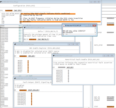

aligned with Reference manual:

Fault -same config as above but NCF_E enabled

2. Bi-stable protocol PS=1
Normal


Fault -same config as above but NCF_E enabled
I am not able to catch the fault state on the scope.
3. Bi-stable protocol PS=0 and CM=1
I am not able to catch the fault state on the scope.
I will add measurement later when I find out what is the root cause.
Best regards,
Peter
Thanks Peter. Maybe there are missing screenshots. In the two which include EOUT_SIG_E0, it is set to 0x00. And I don't see MSCR in any screenshots.
Hello,
Normal Mode and Fault Mode screenshots, similar to what I see. Why is this? Shouldn't they be changing? Or is there something missing with the configuration?
Yes, looks like I have posted twice the same screenshot.
The fault/config mode will have the same behavior (fault) on outputs. To measure this you will need a trigger on oscilloscope to catch the fault state as there is only small time window for fault. Alarm state. Once expired the FCCU or FOSU will reset the device and with it also the pins and config of FCCU.
1. SSS=1 setting for MSCR143 and MSCR144
2. Non-critical Fault-State EOUT Signaling Enable (EOUT_SIG_EN0 = 0x000000ff)
Yes, this is essential for EOUT signaling.
My configuration of FCCU can be seen on debugger screenshots. + the pins config.
Best regards,
Peter
When in fault mode with EOUT enabled, does the FCCU set output on ERR0 and ERR1 with push-pull, or with open drain / hi-z?
Thanks Peter. It looks like ERR0 and ERR1 pins did not change between your Normal Mode and Fault Mode screenshots, similar to what I see. Why is this? Shouldn't they be changing? Or is there something missing with the configuration?
By the way, I am also doing these two things discussed in the previous support case #00696653 before testing. Were these also set for your measurements above?
Thank you
Mike
Hello,
I have did the measurements:
Here are the results:
1. BI-stable protocol PS=1


and measurement:
2. Bi-stable protocol PS=0

and measurement

3. Bi-stable protocol PS=0 and SM=1


normal mode

Fault mode

Best regards,
Peter