
- Forums
- Product Forums
- General Purpose MicrocontrollersGeneral Purpose Microcontrollers
- i.MX Forumsi.MX Forums
- QorIQ Processing PlatformsQorIQ Processing Platforms
- Identification and SecurityIdentification and Security
- Power ManagementPower Management
- Wireless ConnectivityWireless Connectivity
- RFID / NFCRFID / NFC
- Advanced AnalogAdvanced Analog
- Neural Processing UnitsNeural Processing Units
- MCX Microcontrollers
- S32G
- S32K
- S32V
- MPC5xxx
- Other NXP Products
- S12 / MagniV Microcontrollers
- Powertrain and Electrification Analog Drivers
- Sensors
- Vybrid Processors
- Digital Signal Controllers
- 8-bit Microcontrollers
- ColdFire/68K Microcontrollers and Processors
- PowerQUICC Processors
- OSBDM and TBDML
- S32M
- S32Z/E
-
- Solution Forums
- Software Forums
- MCUXpresso Software and ToolsMCUXpresso Software and Tools
- CodeWarriorCodeWarrior
- MQX Software SolutionsMQX Software Solutions
- Model-Based Design Toolbox (MBDT)Model-Based Design Toolbox (MBDT)
- FreeMASTER
- eIQ Machine Learning Software
- Embedded Software and Tools Clinic
- S32 SDK
- S32 Design Studio
- GUI Guider
- Zephyr Project
- Voice Technology
- Application Software Packs
- Secure Provisioning SDK (SPSDK)
- Processor Expert Software
- Generative AI & LLMs
-
- Topics
- Mobile Robotics - Drones and RoversMobile Robotics - Drones and Rovers
- NXP Training ContentNXP Training Content
- University ProgramsUniversity Programs
- Rapid IoT
- NXP Designs
- SafeAssure-Community
- OSS Security & Maintenance
- Using Our Community
-
- Cloud Lab Forums
-
- Knowledge Bases
- ARM Microcontrollers
- i.MX Processors
- Identification and Security
- Model-Based Design Toolbox (MBDT)
- QorIQ Processing Platforms
- S32 Automotive Processing Platform
- Wireless Connectivity
- CodeWarrior
- MCUXpresso Suite of Software and Tools
- MQX Software Solutions
- RFID / NFC
- Advanced Analog
- Neural Processing Units
-
- NXP Tech Blogs
- Home
- :
- 基于模型的设计工具箱(MBDT)
- :
- 基于模型的设计工具箱(MBDT)
- :
- S32K396 DIO from example - LED D34 & 33 wrong default config???
S32K396 DIO from example - LED D34 & 33 wrong default config???
Hello,
I am using S32K396-BGA-DC1 board, with Simulink in matlab2024a.
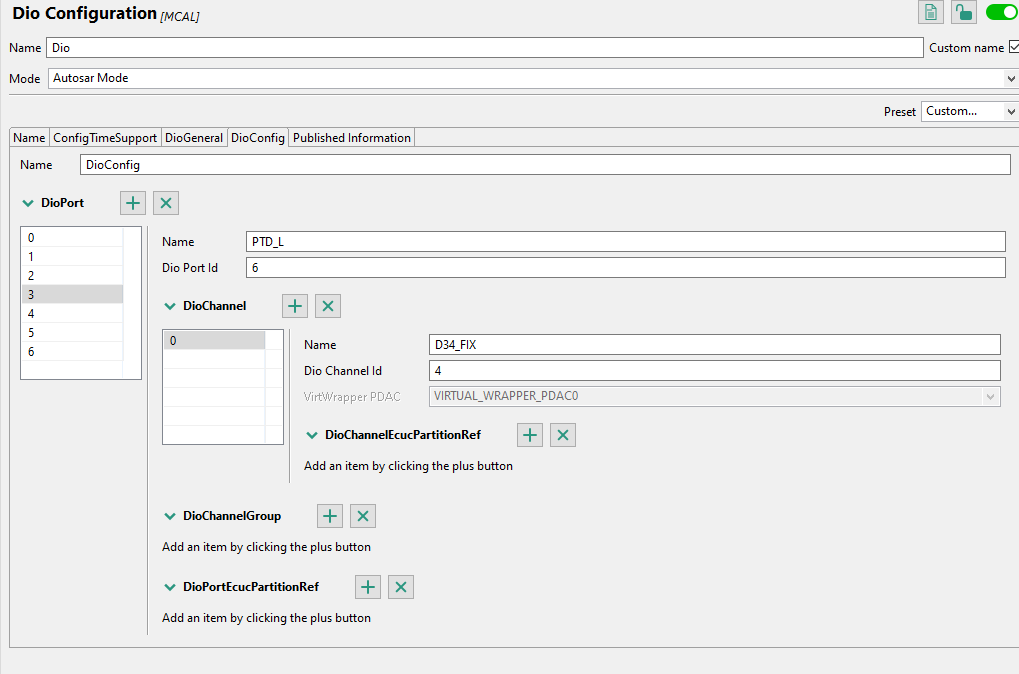
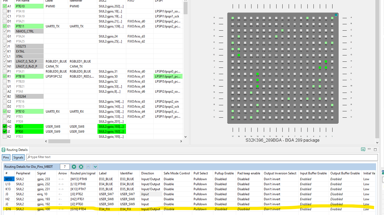
I am trying to re-use the example "s32k37x_s32k39x_dio_ebt" because I noticed that by default, the D33 & D34, are wrong configured in the example project (see fig. 1 & 2) Is that true? . After changing the .mex by adding the correct new channel and configuring it (see fig. 3 & 4), I cannot see the led blinking. I checked that the SW are working ok with freemaster.
Can you please help me with this issue, I attached the modified project.
Thanks, Agustin.
已解决! 转到解答。
Hi, @agus_idiada,
The latest version of the S32K3 Toolbox (1.5.0) provides support for both XS32K396-BGA-DC and XS32K396-BGA-DC1, but in different ways. These are two different revisions of the S32K396 hardware board.
1. The first revision, XS32K396-BGA-DC, is used for the default project implementation of the S32K396-Q289 hardware board, inside the devices folder (toolbox_root\mbdtbx_s32k3\devices\S32K396-Q289). In this folder you can find the configuration of this specific hardware board revision, which has the LEDs routed to PTH7 (D35_BLUE), PTH8 (D34_BLUE) and PTH9 (D33_BLUE), as illustrated in your screenshot 2.png.

2. The second version, XS32K396-BGA-DC1, is a different board revision than the previous one, and which has a slightly different configuration. This revision's implementation is used as a custom configuration, and you can find it inside the custom_projects folder, under devices (toolbox_root\mbdtbx_s32k3\devices\custom_projects\XS32K396-BGA-DC1). In this folder you can find the configuration of this specific hardware board revision, which has the LEDs routed to PTH7 (D35_BLUE), PTD4 (D34_BLUE) and PTD5 (D33_BLUE), as illustrated in your screenshot 3.png.

Regarding the custom project usage, the toolbox provides support for users to create their own custom default projects. This could be very useful when having a custom board design, or, as in our case, a different revision of the same board. For the applications delivered with the toolbox and newly created models, the Default Configuration Template will be set automatically to the location of the default project the toolbox provides, according to the selected Hardware Part and Configuration Tool.

The Browse button will open the Windows Explorer allowing the selection of a different project to be used as the default one for the model. You can choose one of the projects delivered with the toolbox, or a different configuration you might have created.

After you correctly set the custom configuration project, you can successfully use in your application.
Let us know if you have other issues.
Best regards,
Dragos
Hi, @agus_idiada,
The latest version of the S32K3 Toolbox (1.5.0) provides support for both XS32K396-BGA-DC and XS32K396-BGA-DC1, but in different ways. These are two different revisions of the S32K396 hardware board.
1. The first revision, XS32K396-BGA-DC, is used for the default project implementation of the S32K396-Q289 hardware board, inside the devices folder (toolbox_root\mbdtbx_s32k3\devices\S32K396-Q289). In this folder you can find the configuration of this specific hardware board revision, which has the LEDs routed to PTH7 (D35_BLUE), PTH8 (D34_BLUE) and PTH9 (D33_BLUE), as illustrated in your screenshot 2.png.
2. The second version, XS32K396-BGA-DC1, is a different board revision than the previous one, and which has a slightly different configuration. This revision's implementation is used as a custom configuration, and you can find it inside the custom_projects folder, under devices (toolbox_root\mbdtbx_s32k3\devices\custom_projects\XS32K396-BGA-DC1). In this folder you can find the configuration of this specific hardware board revision, which has the LEDs routed to PTH7 (D35_BLUE), PTD4 (D34_BLUE) and PTD5 (D33_BLUE), as illustrated in your screenshot 3.png.
Regarding the custom project usage, the toolbox provides support for users to create their own custom default projects. This could be very useful when having a custom board design, or, as in our case, a different revision of the same board. For the applications delivered with the toolbox and newly created models, the Default Configuration Template will be set automatically to the location of the default project the toolbox provides, according to the selected Hardware Part and Configuration Tool.
The Browse button will open the Windows Explorer allowing the selection of a different project to be used as the default one for the model. You can choose one of the projects delivered with the toolbox, or a different configuration you might have created.
After you correctly set the custom configuration project, you can successfully use in your application.
Let us know if you have other issues.
Best regards,
Dragos