
- Forums
- Product Forums
- General Purpose MicrocontrollersGeneral Purpose Microcontrollers
- i.MX Forumsi.MX Forums
- QorIQ Processing PlatformsQorIQ Processing Platforms
- Identification and SecurityIdentification and Security
- Power ManagementPower Management
- Wireless ConnectivityWireless Connectivity
- RFID / NFCRFID / NFC
- Advanced AnalogAdvanced Analog
- Neural Processing UnitsNeural Processing Units
- MCX Microcontrollers
- S32G
- S32K
- S32V
- MPC5xxx
- Other NXP Products
- S12 / MagniV Microcontrollers
- Powertrain and Electrification Analog Drivers
- Sensors
- Vybrid Processors
- Digital Signal Controllers
- 8-bit Microcontrollers
- ColdFire/68K Microcontrollers and Processors
- PowerQUICC Processors
- OSBDM and TBDML
- S32M
- S32Z/E
-
- Solution Forums
- Software Forums
- MCUXpresso Software and ToolsMCUXpresso Software and Tools
- CodeWarriorCodeWarrior
- MQX Software SolutionsMQX Software Solutions
- Model-Based Design Toolbox (MBDT)Model-Based Design Toolbox (MBDT)
- FreeMASTER
- eIQ Machine Learning Software
- Embedded Software and Tools Clinic
- S32 SDK
- S32 Design Studio
- GUI Guider
- Zephyr Project
- Voice Technology
- Application Software Packs
- Secure Provisioning SDK (SPSDK)
- Processor Expert Software
- Generative AI & LLMs
-
- Topics
- Mobile Robotics - Drones and RoversMobile Robotics - Drones and Rovers
- NXP Training ContentNXP Training Content
- University ProgramsUniversity Programs
- Rapid IoT
- NXP Designs
- SafeAssure-Community
- OSS Security & Maintenance
- Using Our Community
-
- Cloud Lab Forums
-
- Knowledge Bases
- ARM Microcontrollers
- i.MX Processors
- Identification and Security
- Model-Based Design Toolbox (MBDT)
- QorIQ Processing Platforms
- S32 Automotive Processing Platform
- Wireless Connectivity
- CodeWarrior
- MCUXpresso Suite of Software and Tools
- MQX Software Solutions
- RFID / NFC
- Advanced Analog
- Neural Processing Units
-
- NXP Tech Blogs
- Home
- :
- 基于模型的设计工具箱(MBDT)
- :
- 基于模型的设计工具箱(MBDT)
- :
- S32K: FTM Input Edge Capture - Timestamp
S32K: FTM Input Edge Capture - Timestamp

Hallo,
I'm working with the S32K144 Evaluation Board, MPC338xxx Evaluation Board and MBT.
I'm attempting to determine the time between the teeth on a flywheel (Teeth: 9 existing + 3 missing) from the crankshaft speed sensor. To achieve this I'm using the FTM-Input Edge Capture Block. For my model validation I'm also measuring the voltage from the crankshaft speed sensor using ADC.
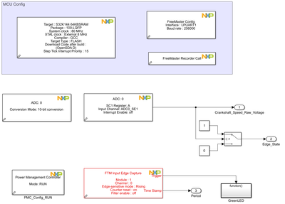
Within Freemaster I can see that the signal from the sensor is good and that the TimeStamp triggered by the FTM aligns perfectly with the voltage signal generated from the tooth.
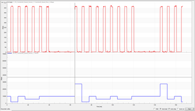
My problem though, is that the counter values I receive from the FTM don't make sense in regards to time. 9 of the teeth are equally separated, but the counter values for each of the teeth can vary widely.
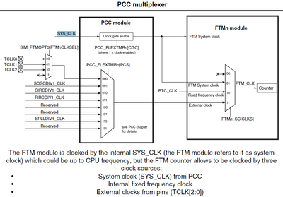
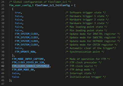
Reading the documentation and reviewing the code from Simulink, the FTM-Clock appears to be SYS_CLK = 80 MHz.
The flywheel is rotating at 750rpm
750 rpm --> 13Hz --> 0,077 seconds per revolution
I have a prescale factor of 128. Therefore I believe my Clock is 625 kHz and that the counter isn't overflowing.
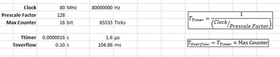
I'm stuck and would appreciate any help. I've attached a measurement file from Freemaster. In the file the timing from the board aligns with the rising edges, but the timestamp (ticks) don't correlate.
Additional question, can I change the source clock for the FTM in MBT?
If not, how can? Are the examples somewhere?
Is there a way to incorporate a counter for when the counter overflows?
Thanks for any help, it's much appreciated.
已解决! 转到解答。

 adriantudor
@Sam_ECU hi,
I have modified your example by adding PWM block to generate 150Hz pulses. Then I used a wire jumper to connect PTC4 (used by FTM input block) to PTC0 (used to generate 150Hz PWM pulses). As you can see in FreeMaster project, the output value of the FTM input capture is accurate (about 4165).

I think the main problem with FTM input capture value, for your particular case, is an electrical noise overlapped on the signal connected to the FTM input capture. Or maybe your signal has a different voltage level than what is expected. You can verify that by connecting an oscilloscope to the FTM input capture (where the 9 teeth signal is connected) and measure it.
Hope that helps.
Best regards,
Adrian
adriantudor
@Sam_ECU hi,
I have done some calculations and it seems that you are trying to measure a 150Hz pulse (which corresponds to 12 teeth for 1 revolution) @750rpm speed and that should be possible to measure using FTM input capture @80Mhz clock input and 128 prescaler. The FTM input period should be around 4166.
Can send us your model to investigate?
Thank you,
Adrian
adriantudor
@Sam_ECU hi,
I have modified your example by adding PWM block to generate 150Hz pulses. Then I used a wire jumper to connect PTC4 (used by FTM input block) to PTC0 (used to generate 150Hz PWM pulses). As you can see in FreeMaster project, the output value of the FTM input capture is accurate (about 4165).
I think the main problem with FTM input capture value, for your particular case, is an electrical noise overlapped on the signal connected to the FTM input capture. Or maybe your signal has a different voltage level than what is expected. You can verify that by connecting an oscilloscope to the FTM input capture (where the 9 teeth signal is connected) and measure it.
Hope that helps.
Best regards,
Adrian
Hello Adrian,@adriantudor
So I partly found the issue to the problem. I'm unsure as to why, but the code wasn't being flashed to the board. I've no idea of the setting issue in Simulink (as the C code and .elf file were generated, measurements were possible with freemaster), but there is an error somewhere.
Once I started using an older version of my model things started behaving as predicted again. The FTM is working as expected.
But due to your comments I looked at the issue with an oscilloscope and discovered that in general the signal looks good:
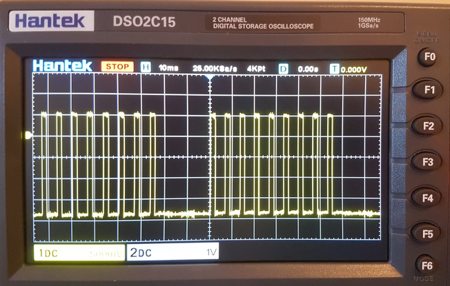
But sometimes I observe noise on the signal:
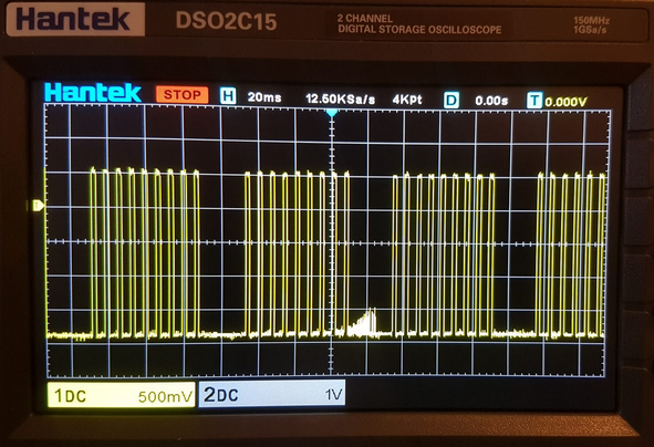
But the noise is present when the sensor is unplugged. The source of the noise is the S32-Board.
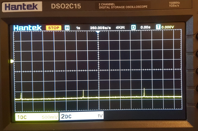
The board is grounded (J3-11 to mains ground). Is there an another known source of noise from the board that I'm not aware of and perhaps a solution?
Also, we can I find additional information to the FTM Filter in MBT? And is it possible to change the input source for the FTM in MBT (Like with the Low Power Timer)?
adriantudor
@Sam_ECU hi,
It is possible that this electric noise that you see on the FTM input when the sensor is not connected, to be generated by a switching voltage regulator used to power S32K mcu. But this noise should not affect your signal as long as your sensor is connected and powered to the dev board. As I see, in the second picture, the maximum voltage level is about 500mV. And because the input of FTM is configured as a digital TTL input, this electrical noise can't affect your readings. If the input has been configured as ADC input, and if you had seen this electrical noise, then that would have been a problem.
Anyway, this kind of noise appears on the inputs due to the very high impedance of the inputs. When the sensor is not powered, the impedance of the input pin is very high, due to that the electrical noise from the proximity is radiated in the air, the PCB copper lines capture some of the higher signals, and because nothing "consume" it or block it, you can see it with the oscilloscope. But when the sensor is powered, the output impedance of this sensor lowers the electrical noises. To reduce this noise, captured even by wire that connects your sensor to the dev board, you can use a shielded cable and connect the shield to the ground, or you can decrease the impedance of this line even more by connecting a resistor between this input pin and ground. But be careful, if you want to lower the impedance, to not damage your sensor. This resistor must be correlated with the electrical characteristic of your sensor.
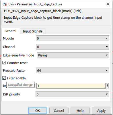
If you want more info about the FTM filter, first check the help of that block and then in the reference manual of the S32K144.
I'm not sure that I understand correctly your question about LPTMR connected as an input to FTM, but if you want to use LPTMR, you can find a few examples with LPTMR in the toolbox.
Best regards,
Adrian
