
- Forums
- Product Forums
- General Purpose MicrocontrollersGeneral Purpose Microcontrollers
- i.MX Forumsi.MX Forums
- QorIQ Processing PlatformsQorIQ Processing Platforms
- Identification and SecurityIdentification and Security
- Power ManagementPower Management
- Wireless ConnectivityWireless Connectivity
- RFID / NFCRFID / NFC
- Advanced AnalogAdvanced Analog
- MCX Microcontrollers
- S32G
- S32K
- S32V
- MPC5xxx
- Other NXP Products
- S12 / MagniV Microcontrollers
- Powertrain and Electrification Analog Drivers
- Sensors
- Vybrid Processors
- Digital Signal Controllers
- 8-bit Microcontrollers
- ColdFire/68K Microcontrollers and Processors
- PowerQUICC Processors
- OSBDM and TBDML
- S32M
- S32Z/E
-
- Solution Forums
- Software Forums
- MCUXpresso Software and ToolsMCUXpresso Software and Tools
- CodeWarriorCodeWarrior
- MQX Software SolutionsMQX Software Solutions
- Model-Based Design Toolbox (MBDT)Model-Based Design Toolbox (MBDT)
- FreeMASTER
- eIQ Machine Learning Software
- Embedded Software and Tools Clinic
- S32 SDK
- S32 Design Studio
- GUI Guider
- Zephyr Project
- Voice Technology
- Application Software Packs
- Secure Provisioning SDK (SPSDK)
- Processor Expert Software
- Generative AI & LLMs
-
- Topics
- Mobile Robotics - Drones and RoversMobile Robotics - Drones and Rovers
- NXP Training ContentNXP Training Content
- University ProgramsUniversity Programs
- Rapid IoT
- NXP Designs
- SafeAssure-Community
- OSS Security & Maintenance
- Using Our Community
-
- Cloud Lab Forums
-
- Knowledge Bases
- ARM Microcontrollers
- i.MX Processors
- Identification and Security
- Model-Based Design Toolbox (MBDT)
- QorIQ Processing Platforms
- S32 Automotive Processing Platform
- Wireless Connectivity
- CodeWarrior
- MCUXpresso Suite of Software and Tools
- MQX Software Solutions
- RFID / NFC
- Advanced Analog
-
- NXP Tech Blogs
- Home
- :
- 基于模型的设计工具箱(MBDT)
- :
- 基于模型的设计工具箱(MBDT)
- :
- Re: NXP MATLAB Toolbox Installer
NXP MATLAB Toolbox Installer
NXP MATLAB Toolbox Installer
Hello,
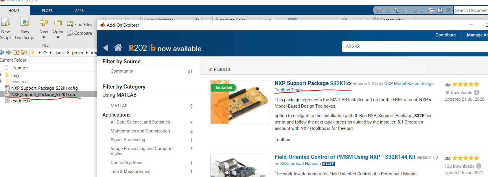
We have to report some issue that came up while installing MATLAB Toolbos for S32K344:
“The support package installer available on the MATLAB add-ons page does not contain the S32K3, it only supports the S32k1 as shown by the NXP_support_package_s32K1xx.m file underlined in the image attached, hence if the installer is used to install the MBDToolbox_S32K3xx_1.0.0_20210607.mltbx. there is an installer mismatch, please can you guide us on how the installation is supposed to be done if this is an outdated method, and if its not please provide the latest installer.m file that's required for the S32k3 model based design tool box”
Please find a picture attached.
Can we get an updated “installation guide” & “S32K344 Support Package” from NXP?
Thanks for your time and help in advance.
Hi @sh_dhanasekaran,
A possible cause for the issue you are encountering could be represented by a mismatch between the toolbox version that you have installed, and the version selected inside the Installation Guide UI, which is 1.3.0.
As the latest version of MBDT for S32K3 is indeed 1.3.0, could you please check if this is the one installed on your PC?
In case you need to upgrade it, and we recommend such an upgrade so that you could benefit from the latest enhancements and functionalities, you could follow the steps from the Installation Guide - these will allow you to download and install v1.3.0. Then, you could try again verifying the toolbox installation and activating its license.
Hope this helps,
Irina
Hello @BrunoSenzio ,
Thank you for writing to us!
If our customer already has the MBDToolbox_S32K3xx_1.0.0_20210607.mltbx file, in order to install the toolbox they have to drag and drop the .mltbx file inside MATLAB Command Window and the installation process will start automatically. The licensing process is the same as for the S32K1: our customer has to go on the NXP website and follow a similar license request procedure.
The requested installation support package will be available in MATLAB AddOns soon.
Hope this helps,
Marius
Hello Marius,
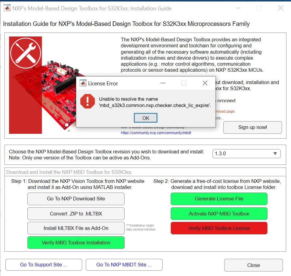
the above question was from me, I have installed the MBD toolbox and followed the installation guide in the help folder, apart from using EB tresos, I chose s32 configuration instead. I still can't connect to the S32k3 development board due to the following error below, and my best guess is I don't have the drivers required to connect to the hardware as shown by the error in my device manager in the second picture below when I connect the hardware. do you know of a way to correct this.
Hello @kamalwolly,
The toolbox can use both S32CT or EBT, the default projects used for the code have the same settings. Indeed you need to install the P&E Micro's Multilink Universal driver from here: http://www.pemicro.com/downloads/download_file.cfm?download_id=346
Also, It will be a good practice to install as well the FT2232D USB2Serial Driver from this page https://ftdichip.com/products/ft2232d/ . This USB2Serial converter comes on the S32K344 EVB.
Hope this helps,
Marius
Thanks for the tip, I can upload to the controller. I'm having problems with putting the controller in external mode. This I presume is due to the COM port being configured inaccurately since when I click "monitor and tune" the firmware uploads onto the board successfully via the OPENSDA micro-USB port. I cant find the COM port number in the device manager on my computer, neither does it automatically update in the model settings when I reconnect the eval board to the computer. Is this something you've experienced and do you know what steps I can take to remedy the problem?
regards,
Kamal Wolly
Hello @kamalwolly
Indeed you have to specify the COM port associated with the board.

Let's have a look at the image above.
1 and 2 is the 12V power supply, in order to supply the board, you have to plug in a 12V jack and to turn the button until those 3 leds are lighting.
3 is the USB2Serial converter. You have to connect the USB port to be able to communicate with the board. In both PIL and External mode, you need this cable for the communication between MATLAB's host PC and the board.
4 is the internal debugger. You have to connect this cable to be able to flash the board.
Now, in your case, once you have connected cable 3, go to device manager, and see which ports have appeared. In my case, are the COMs 44 and 45. They are 2 because the board has a dual USB2Serial, thus 2 channels, and the LPUART13 of the MCU is connected to the FTDI's channel B. In most of cases, the channel B is connected to the COM with the higher number.

Not that we know the port, in my case is COM45 but it will be different on your side, go to Hardware Settings in Simulink, select External Mode and under Serial port type the new COM port, in my case COM45.

Hope this helps,
Marius
Thanks,
worked like magic, I've got two more problems and hopefully I should be good to go,
Firstly, I can only Monitor and tune the external mode example provided by NXP, whenever I try to do that with any other example or projects I have created that builds and deploys. It brings up an error that COM 1 fails to open when I've clearly setup com 32 for external mode (Image below)
Secondly, when It comes to peripheral configuration, am I wrong in presuming configuring pins for PWM, SPI, and say ADC for the board in question can be done in Simulink or do we really have to hit configure button and go into the s32 design studio pin configurator. and if indeed the pins need to be configured in s32 design studio, please send can you send me documentation that would help guide me through this, because I tried adding an additional PWM channel (channel 2 or 3 ) to the "PWM independent" example and the output on the A2 and A3 pins has no output.
thanks once gain
.png)
Hi @kamalwolly
Related to the External Mode issue, can you please indicate which Matlab version you are using?
As a suggestion, you could try setting the same COM port in both the External Mode and PIL groups from the Hardware Settings. Additionally, in case this does not provide the expected behavior, try by enabling also the Verbose option in the External Mode group.
Best Regards,
Irina
my MATLAB version is 2021a, I've attempted both solutions you suggested, the firmware does download onto the hardware, it just fails to initialize the external mode.
Hi @kamalwolly
While we take a look into the External Mode issue that you have encountered, I will provide some information related to the second question from your post.
MBD Toolbox provides a default peripherals, pins and clocks configuration that can be used for Simulink applications development without having to open the external configuration tool. However, if you need additional settings or want to modify the existing ones, the way to do it is to press the Configure button and make your updates inside the project.
For accessing documentation, you can press the Help button on the PWM Simulink block mask.
In the opened file, scroll down to the Code Generation section. Here, you will find links to 2 different documents.
The first one is the PWM component User Manual, provided by the Real Time Drivers MBDT is using. It contains details related to the configurable fields for the PWM component and PWM API functions. If the link does not open the expected document, you can also find it by navigating to the S32K3_RTD/SW32K3_RTD_4.4_0.9.0/eclipse/plugins folder. Just open the folder corresponding to the component you would like to find more about, in this case Pwm_TS_... and then go to the doc folder inside.
Clicking the second link will download the AUTOSAR documentation archive (in this case IO.zip) where you can find the specifications of the PWM driver.
Hope this helps,
Irina