
- Forums
- Product Forums
- General Purpose MicrocontrollersGeneral Purpose Microcontrollers
- i.MX Forumsi.MX Forums
- QorIQ Processing PlatformsQorIQ Processing Platforms
- Identification and SecurityIdentification and Security
- Power ManagementPower Management
- Wireless ConnectivityWireless Connectivity
- RFID / NFCRFID / NFC
- Advanced AnalogAdvanced Analog
- Neural Processing UnitsNeural Processing Units
- MCX Microcontrollers
- S32G
- S32K
- S32V
- MPC5xxx
- Other NXP Products
- S12 / MagniV Microcontrollers
- Powertrain and Electrification Analog Drivers
- Sensors
- Vybrid Processors
- Digital Signal Controllers
- 8-bit Microcontrollers
- ColdFire/68K Microcontrollers and Processors
- PowerQUICC Processors
- OSBDM and TBDML
- S32M
- S32Z/E
-
- Solution Forums
- Software Forums
- MCUXpresso Software and ToolsMCUXpresso Software and Tools
- CodeWarriorCodeWarrior
- MQX Software SolutionsMQX Software Solutions
- Model-Based Design Toolbox (MBDT)Model-Based Design Toolbox (MBDT)
- FreeMASTER
- eIQ Machine Learning Software
- Embedded Software and Tools Clinic
- S32 SDK
- S32 Design Studio
- GUI Guider
- Zephyr Project
- Voice Technology
- Application Software Packs
- Secure Provisioning SDK (SPSDK)
- Processor Expert Software
- Generative AI & LLMs
-
- Topics
- Mobile Robotics - Drones and RoversMobile Robotics - Drones and Rovers
- NXP Training ContentNXP Training Content
- University ProgramsUniversity Programs
- Rapid IoT
- NXP Designs
- SafeAssure-Community
- OSS Security & Maintenance
- Using Our Community
-
- Cloud Lab Forums
-
- Knowledge Bases
- ARM Microcontrollers
- i.MX Processors
- Identification and Security
- Model-Based Design Toolbox (MBDT)
- QorIQ Processing Platforms
- S32 Automotive Processing Platform
- Wireless Connectivity
- CodeWarrior
- MCUXpresso Suite of Software and Tools
- MQX Software Solutions
- RFID / NFC
- Advanced Analog
- Neural Processing Units
-
- NXP Tech Blogs
- Home
- :
- Product Forums
- :
- MPC5xxx
- :
- How to configure MPC5643L without using external crystal?
How to configure MPC5643L without using external crystal?
- Subscribe to RSS Feed
- Mark Topic as New
- Mark Topic as Read
- Float this Topic for Current User
- Bookmark
- Subscribe
- Mute
- Printer Friendly Page
How to configure MPC5643L without using external crystal?

- Mark as New
- Bookmark
- Subscribe
- Mute
- Subscribe to RSS Feed
- Permalink
- Report Inappropriate Content
I'm trying to configure MPC5643L by running with internal RC oscillator only. I'm currently running on a 16 MHz external crystal. The most likely way is to configure FMPLL0 and FMPLL1 to use internal RC oscillator. Right now, all clocks are driven by PLL0 and PLL1.
Please help me to do so.
Thanks!

 davidtosenovjan
- Mark as New
- Bookmark
- Subscribe
- Mute
- Subscribe to RSS Feed
- Permalink
- Report Inappropriate Content
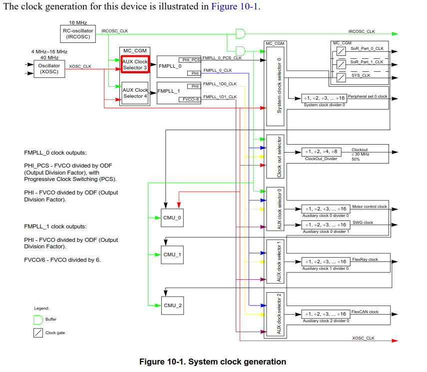
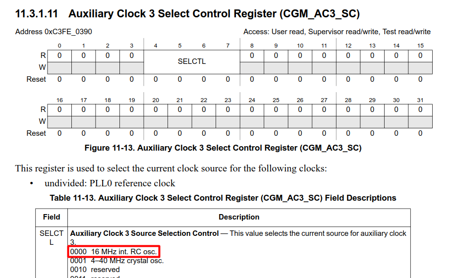
Such configuration is possible by configuration of AUX Clock Selector, but internal RC oscillator is imprecise clock thus it is not being used too often.
- Mark as New
- Bookmark
- Subscribe
- Mute
- Subscribe to RSS Feed
- Permalink
- Report Inappropriate Content
That’s what I did by configuring:
1) CGM_AC3_SC register to select 16 MHz RC osc for PLL0
2) CGM_AC4_SC register to select 16 MHz RC osc for PLL1
However, the configuration was never successful. The program execution stuck at the while loop, waiting for PLL to lock.
By further reading MPC5643L user manual, chapter 27, Frequency-Modulated Phase-Locked Loop (FMPLL),
It never mentioned inter RC oscillator can be used as the colock source for PLL.
Do you have sample code I can try?
Thanks,
Ning
//////////////////////// The following are the code I used ////////////////////////////////////////////
/* Oscillator Output is Disabled as rootclock */
/* The End of Count Value for XOSC = 0x80 */
/* The XOSC Clock Interrupt: Disabled */
CGM.AC3_SC.B.SELCTL = 0; /* Select 16 MHz RC osc for PLL0 */
/* PLL0 reference clock source : 16MHz IRC */
CGM.AC4_SC.B.SELCTL = 0; /* Select 16 MHz RC osc for PLL1 */
/* PLL1 reference clock source : 16MHz IRC*/
CGM.FMPLL[0].CR.R = PLL_VALUE_0 | (0x01 << 8);
CGM.FMPLL[0].MR.R = 0x00000000;
/* The selected Spread Type: Down Spread */
/* The Modulation Period for FMPLL0: 0 */
/* Frequency modulation for PLL: Disabled */
/* The Increment Step for FMPLL0: 0 */
CGM.FMPLL[1].CR.R = PLL_VALUE_1 | (0x01 << 8);
CGM.FMPLL[1].MR.R = 0x00000000;
/* The selected Spread Type: Down Spread */
/* The Modulation Period for FMPLL1: 0 */
/* Frequency modulation for PLL: Disabled */
/* The Increment Step for FMPLL1: 0 */
/*
davidtosenovjan
- Mark as New
- Bookmark
- Subscribe
- Mute
- Subscribe to RSS Feed
- Permalink
- Report Inappropriate Content
Founded. The system cannot run without XOSC, otherwise PLL does not lock (even it is supposed to lock to IRC clock).
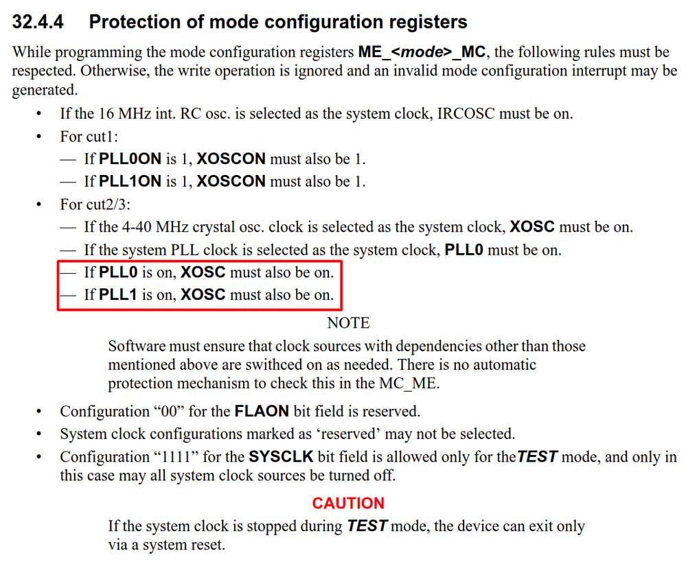

In this case I don't see any benefit to clock the system only by IRC clock as external oscillator must run anyway.
- Mark as New
- Bookmark
- Subscribe
- Mute
- Subscribe to RSS Feed
- Permalink
- Report Inappropriate Content
David,
Thanks!
This agrees with my tests. Even I can configure PLL0/PLL1 using internal RC, the PLL does not lock.
I’ve made two versions of board:
1) a circuit has external crystal, but configured PLL0/PLL1 using internal crystal RC: it worked.
2) A circuit has external crystal removed, PLL can not lock.
Thanks for your kind help!
Ning
 davidtosenovjan
- Mark as New
- Bookmark
- Subscribe
- Mute
- Subscribe to RSS Feed
- Permalink
- Report Inappropriate Content
I have tried it and it seems it is possible to run the whole system from IRC but XOSC still must run otherwise PLL does not stabilize. I am not sure why it is so. I am investigating.
- Mark as New
- Bookmark
- Subscribe
- Mute
- Subscribe to RSS Feed
- Permalink
- Report Inappropriate Content

