
- Forums
- Product Forums
- General Purpose MicrocontrollersGeneral Purpose Microcontrollers
- i.MX Forumsi.MX Forums
- QorIQ Processing PlatformsQorIQ Processing Platforms
- Identification and SecurityIdentification and Security
- Power ManagementPower Management
- Wireless ConnectivityWireless Connectivity
- RFID / NFCRFID / NFC
- Advanced AnalogAdvanced Analog
- Neural Processing UnitsNeural Processing Units
- MCX Microcontrollers
- S32G
- S32K
- S32V
- MPC5xxx
- Other NXP Products
- S12 / MagniV Microcontrollers
- Powertrain and Electrification Analog Drivers
- Sensors
- Vybrid Processors
- Digital Signal Controllers
- 8-bit Microcontrollers
- ColdFire/68K Microcontrollers and Processors
- PowerQUICC Processors
- OSBDM and TBDML
- S32M
- S32Z/E
-
- Solution Forums
- Software Forums
- MCUXpresso Software and ToolsMCUXpresso Software and Tools
- CodeWarriorCodeWarrior
- MQX Software SolutionsMQX Software Solutions
- Model-Based Design Toolbox (MBDT)Model-Based Design Toolbox (MBDT)
- FreeMASTER
- eIQ Machine Learning Software
- Embedded Software and Tools Clinic
- S32 SDK
- S32 Design Studio
- GUI Guider
- Zephyr Project
- Voice Technology
- Application Software Packs
- Secure Provisioning SDK (SPSDK)
- Processor Expert Software
- Generative AI & LLMs
-
- Topics
- Mobile Robotics - Drones and RoversMobile Robotics - Drones and Rovers
- NXP Training ContentNXP Training Content
- University ProgramsUniversity Programs
- Rapid IoT
- NXP Designs
- SafeAssure-Community
- OSS Security & Maintenance
- Using Our Community
-
- Cloud Lab Forums
-
- Knowledge Bases
- ARM Microcontrollers
- i.MX Processors
- Identification and Security
- Model-Based Design Toolbox (MBDT)
- QorIQ Processing Platforms
- S32 Automotive Processing Platform
- Wireless Connectivity
- CodeWarrior
- MCUXpresso Suite of Software and Tools
- MQX Software Solutions
- RFID / NFC
- Advanced Analog
- Neural Processing Units
-
- NXP Tech Blogs
- Home
- :
- MCUXpresso Software and Tools
- :
- MCUXpresso SDK
- :
- Problem with SDK freertos SPI example
Problem with SDK freertos SPI example
- Subscribe to RSS Feed
- Mark Topic as New
- Mark Topic as Read
- Float this Topic for Current User
- Bookmark
- Subscribe
- Mute
- Printer Friendly Page
- Mark as New
- Bookmark
- Subscribe
- Mute
- Subscribe to RSS Feed
- Permalink
- Report Inappropriate Content
Hello,
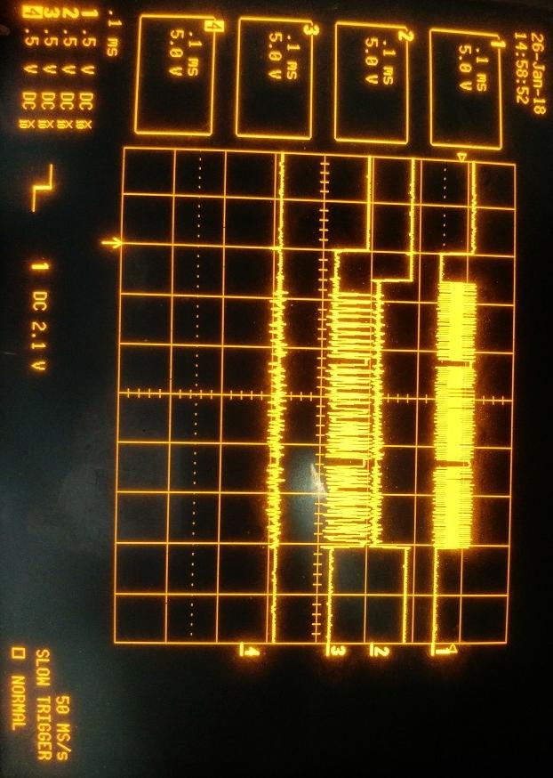
I'm wondering if this forum would be able to help solve my problem running the freertos_spi SDK example? I have imported several SDK examples which have worked, but am not able to get this example to generate the expected output. I have not altered the code from the SDK example code. The serial communication portion works and outputs results as shown in the "UART output" attachment. However this output indicates the test was not successful. I also attached an oscilloscope capture, with channels connected as follows:
CH1 = CLK
CH2 = PCS0
CH3 = SOUT (master MOSI)
CH4 = SIN (master MISO)
The master appears to successfully transmit a message, but the slave does not receive it as indicated by the serial output from the SDK example program. There is no line activity after what is shown in the oscilloscope capture.
I feel confident I have connected the 4 wires correctly, connecting SPI9 (J9 pins 11, 13, 9, 15) to SPI3 (J14 pins 3, 2, 4, 1). I also noted that the above serial response is different if I remove my connecting wires. I have also inserted the JP6 jumper. I have not done anything with JP8, as that is not present on my revC board.
MCUXpresso IDE v10.1.1 [Build 606] [2018-01-02]
SDK_2.x_LPCXpresso54618, SDK Version 2.3.0, Manifest Version 3.2.0
Board: OM13094 CAN-FD kit, lpcxpresso 54618, silkscreen on board is: LPCXpresso546xx Rev C
Micro: LPC54618J512
Thanks,
Matt
Solved! Go to Solution.
- Mark as New
- Bookmark
- Subscribe
- Mute
- Subscribe to RSS Feed
- Permalink
- Report Inappropriate Content
Hello Matt,
As you mentioned before, JP8 is not present on revC boards, however JP8 was replaced for zero ohms links (JS33, JS34, JS35 and JS36).

So you need to make the changes in the zero ohm links, specifically move JS34 and JS35. By default each link is connected to pins 2 and 3 you need to change both of them (JS34 and JS35) to pins 1 and 2. Once you make these changes the demo works correctly.
Have a great day,
Victor.
-----------------------------------------------------------------------------------------------------------------------
Note: If this post answers your question, please click the Correct Answer button. Thank you!
-----------------------------------------------------------------------------------------------------------------------
- Mark as New
- Bookmark
- Subscribe
- Mute
- Subscribe to RSS Feed
- Permalink
- Report Inappropriate Content
Hello Matt,
As you mentioned before, JP8 is not present on revC boards, however JP8 was replaced for zero ohms links (JS33, JS34, JS35 and JS36).
So you need to make the changes in the zero ohm links, specifically move JS34 and JS35. By default each link is connected to pins 2 and 3 you need to change both of them (JS34 and JS35) to pins 1 and 2. Once you make these changes the demo works correctly.
Have a great day,
Victor.
-----------------------------------------------------------------------------------------------------------------------
Note: If this post answers your question, please click the Correct Answer button. Thank you!
-----------------------------------------------------------------------------------------------------------------------
- Mark as New
- Bookmark
- Subscribe
- Mute
- Subscribe to RSS Feed
- Permalink
- Report Inappropriate Content
Thank you, that made it work correctly as you suggested.
Matt