
- Forums
- Product Forums
- General Purpose MicrocontrollersGeneral Purpose Microcontrollers
- i.MX Forumsi.MX Forums
- QorIQ Processing PlatformsQorIQ Processing Platforms
- Identification and SecurityIdentification and Security
- Power ManagementPower Management
- Wireless ConnectivityWireless Connectivity
- RFID / NFCRFID / NFC
- Advanced AnalogAdvanced Analog
- Neural Processing UnitsNeural Processing Units
- MCX Microcontrollers
- S32G
- S32K
- S32V
- MPC5xxx
- Other NXP Products
- S12 / MagniV Microcontrollers
- Powertrain and Electrification Analog Drivers
- Sensors
- Vybrid Processors
- Digital Signal Controllers
- 8-bit Microcontrollers
- ColdFire/68K Microcontrollers and Processors
- PowerQUICC Processors
- OSBDM and TBDML
- S32M
- S32Z/E
-
- Solution Forums
- Software Forums
- MCUXpresso Software and ToolsMCUXpresso Software and Tools
- CodeWarriorCodeWarrior
- MQX Software SolutionsMQX Software Solutions
- Model-Based Design Toolbox (MBDT)Model-Based Design Toolbox (MBDT)
- FreeMASTER
- eIQ Machine Learning Software
- Embedded Software and Tools Clinic
- S32 SDK
- S32 Design Studio
- GUI Guider
- Zephyr Project
- Voice Technology
- Application Software Packs
- Secure Provisioning SDK (SPSDK)
- Processor Expert Software
- Generative AI & LLMs
-
- Topics
- Mobile Robotics - Drones and RoversMobile Robotics - Drones and Rovers
- NXP Training ContentNXP Training Content
- University ProgramsUniversity Programs
- Rapid IoT
- NXP Designs
- SafeAssure-Community
- OSS Security & Maintenance
- Using Our Community
-
- Cloud Lab Forums
-
- Knowledge Bases
- ARM Microcontrollers
- i.MX Processors
- Identification and Security
- Model-Based Design Toolbox (MBDT)
- QorIQ Processing Platforms
- S32 Automotive Processing Platform
- Wireless Connectivity
- CodeWarrior
- MCUXpresso Suite of Software and Tools
- MQX Software Solutions
- RFID / NFC
- Advanced Analog
- Neural Processing Units
-
- NXP Tech Blogs
- Home
- :
- General Purpose Microcontrollers
- :
- LPC Microcontrollers
- :
- Re: Program LPC by UART
Program LPC by UART
- Subscribe to RSS Feed
- Mark Topic as New
- Mark Topic as Read
- Float this Topic for Current User
- Bookmark
- Subscribe
- Mute
- Printer Friendly Page
Program LPC by UART

- Mark as New
- Bookmark
- Subscribe
- Mute
- Subscribe to RSS Feed
- Permalink
- Report Inappropriate Content
Hi All,
I am working on LPC55S69 and need to flash firmware (.bin/.axf etc) via USB-to-Serial (FTDI) cable, the programming connector
I need to design new firmware for a device having LPC55S69, the existing device has a programming connector and a programming cable as given below,

As far as I know to program LPC MCUs we can use ISP Boot mode with Flash Magic, but for that I need to use two more pins of the MCU i.e., ISP and RST, so in total 5 pins (Vcc, Gnd, Rx, Tx, ISP and RST), the ISP and RST of MCU connected to RTS and DTR of the FTDI adaptor (or activate the ISP and RST pins of MCU manually by shorting them to GND)
So I need to know is there “ANY WAY” by which we can program LPC MCUs by only Rx, TX (and Vcc, Gnd), without using ISP and RST pins of MCU (or by connecting ISP and RST internally to some thing which is triggering ISP boot mode).
Or if they have written their own bootloader that can be used without using ISP and RST pins of MCU.

 xiangjun_rong
- Mark as New
- Bookmark
- Subscribe
- Mute
- Subscribe to RSS Feed
- Permalink
- Report Inappropriate Content
Hi,
I suppose that you misunderstood the function of the pins: RST, ISP,uart_TXD and UART_RXD.
First of all, the PIO0_5 pin for LPC55S69 is ISP pin, the RESET_b pin and PIO0_5 pins are not necessary to connect to the FTDI chip, on the LPC55S69 target board, you need to connect the PIO0_5 pin to a button or a jumper so that you can control the PIO0_5 pin high or low after Reset.
The RESET_b pin is required to be connected to a RC circuit and button(the RESET_b pin is low after you press the button).
With PIO0_5 Low during/after Reset, the LPC55S69 enter ISP mode, you can use the FTDI to transfer application code. During the transfer, the PIO0_5 do not need to control, only need to remain low.
With PIO0_5 high during/after Reset, the LPC55S69 executes application code.
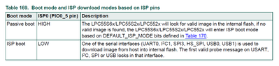
This is the uart pin, you have to use uart0 to transfer application code.
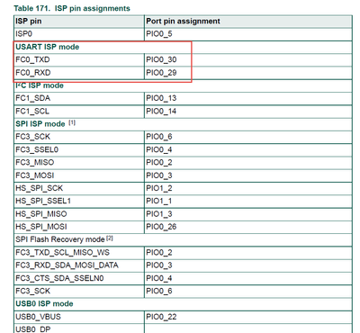
You can use blhost.exe on PC side to download code via uart.
Pls refer to UM11126.pdf
Hope it can help you
BR
XiangJun Rong
- Mark as New
- Bookmark
- Subscribe
- Mute
- Subscribe to RSS Feed
- Permalink
- Report Inappropriate Content
Great thanks for your reply XiangJun Rong sir, actually as I mentioned earlier as far as I know you can activate the ISP and RST pins of MCU manually by using button or a jumper, RC circuit etc, so that the LPC55S69 enter ISP mode, then we can use the FTDI to transfer application code.
What I observed in the PCB the PIO0_5 (ISP pin), RESET_b pin are left floating and in the drawing a pull-up resistor is shown but no button or jumper is there.

As you can see the Reset or ISP pins of MCU are not controllable (by a button etc) by the user, we are just plugging the FTDI to the PCB and able to flash the firmware.
May be they have written their own bootloader and custom PC app to flash the MCU.
Please help me is there “ANY WAY” by which we can program LPC MCUs by only Rx, TX (and Vcc, Gnd), without using ISP and RST pins
Thanks
xiangjun_rong
- Mark as New
- Bookmark
- Subscribe
- Mute
- Subscribe to RSS Feed
- Permalink
- Report Inappropriate Content
Hi,
Yes, the following connection is correct.
The FTDI module is enumerated as a USB device with a COM port when the usb of FTDI is inserted to PC.
You can use the blhost to communicate with the LPC55S69 using the COM port.
For your question, you have to provide power for the LPC55S69 so that the LPC55S69 can work.
If you use LPC55S69, I suggest you order LPC55S59-EVK board and have a test.

Hope it can help you
BR
XiangJun Rong
- Mark as New
- Bookmark
- Subscribe
- Mute
- Subscribe to RSS Feed
- Permalink
- Report Inappropriate Content
Great thanks sir, there is one doubt that I have not activated the PIO0_5 (ISP pin), RESET_b pin of the LPC55S69, they are left floating or a pull-up resistor connected, but no button or jumper is there to pull them Low to enter in ISP mode. So will the LPC55S69 enter into ISP mode? i.e., with the connection above, will I be able to flash firmware to LPC55S69 using blhost ?
I am ordering the LPC55S69-EVK, but want to have some clarity before hands-on.
Thanks
xiangjun_rong
- Mark as New
- Bookmark
- Subscribe
- Mute
- Subscribe to RSS Feed
- Permalink
- Report Inappropriate Content
Hi,
Both the Resetn signal and PIO0_5 signal have internal pull-up resistor, so the two pins can be float if you want to execute application code. If you want to enter boot mode, you can connect a pull-down on the PIO0_5.
But the condition that the LPC55S69 can enter boot mode is it is powered correctly.
Hope it can help you
BR
XiangJun Rong
- Mark as New
- Bookmark
- Subscribe
- Mute
- Subscribe to RSS Feed
- Permalink
- Report Inappropriate Content
Great thanks xiangjun_rong
As we can see in the schematics there is no pull-down on the PIO0_5, even then We are able to program the microcontroller, they have given .sb file.
My problem is that how they are able to program the microcontroller without making pull-down on the PIO0_5 ?, is there any other wayout to enter the microcontroller in programming mode ? maybe via software etc.
Please help me
 ZhangJennie
- Mark as New
- Bookmark
- Subscribe
- Mute
- Subscribe to RSS Feed
- Permalink
- Report Inappropriate Content
Hi aashish1 ,
To enter ISP programming mode, the ISP pin must be inserted. Please refer to the following boot sequence chart, which is extracted from the UM.

Hope this helps,
Jun Zhang
