
- Forums
- Product Forums
- General Purpose MicrocontrollersGeneral Purpose Microcontrollers
- i.MX Forumsi.MX Forums
- QorIQ Processing PlatformsQorIQ Processing Platforms
- Identification and SecurityIdentification and Security
- Power ManagementPower Management
- Wireless ConnectivityWireless Connectivity
- RFID / NFCRFID / NFC
- Advanced AnalogAdvanced Analog
- Neural Processing UnitsNeural Processing Units
- MCX Microcontrollers
- S32G
- S32K
- S32V
- MPC5xxx
- Other NXP Products
- S12 / MagniV Microcontrollers
- Powertrain and Electrification Analog Drivers
- Sensors
- Vybrid Processors
- Digital Signal Controllers
- 8-bit Microcontrollers
- ColdFire/68K Microcontrollers and Processors
- PowerQUICC Processors
- OSBDM and TBDML
- S32M
- S32Z/E
-
- Solution Forums
- Software Forums
- MCUXpresso Software and ToolsMCUXpresso Software and Tools
- CodeWarriorCodeWarrior
- MQX Software SolutionsMQX Software Solutions
- Model-Based Design Toolbox (MBDT)Model-Based Design Toolbox (MBDT)
- FreeMASTER
- eIQ Machine Learning Software
- Embedded Software and Tools Clinic
- S32 SDK
- S32 Design Studio
- GUI Guider
- Zephyr Project
- Voice Technology
- Application Software Packs
- Secure Provisioning SDK (SPSDK)
- Processor Expert Software
- Generative AI & LLMs
-
- Topics
- Mobile Robotics - Drones and RoversMobile Robotics - Drones and Rovers
- NXP Training ContentNXP Training Content
- University ProgramsUniversity Programs
- Rapid IoT
- NXP Designs
- SafeAssure-Community
- OSS Security & Maintenance
- Using Our Community
-
- Cloud Lab Forums
-
- Knowledge Bases
- ARM Microcontrollers
- i.MX Processors
- Identification and Security
- Model-Based Design Toolbox (MBDT)
- QorIQ Processing Platforms
- S32 Automotive Processing Platform
- Wireless Connectivity
- CodeWarrior
- MCUXpresso Suite of Software and Tools
- MQX Software Solutions
- RFID / NFC
- Advanced Analog
- Neural Processing Units
-
- NXP Tech Blogs
- Home
- :
- 汎用マイクロコントローラ
- :
- LPCマイクロコントローラ
- :
- PWM ISSUE - LPC 55s16 Microntroller
PWM ISSUE - LPC 55s16 Microntroller
- RSS フィードを購読する
- トピックを新着としてマーク
- トピックを既読としてマーク
- このトピックを現在のユーザーにフロートします
- ブックマーク
- 購読
- ミュート
- 印刷用ページ

- 新着としてマーク
- ブックマーク
- 購読
- ミュート
- RSS フィードを購読する
- ハイライト
- 印刷
- 不適切なコンテンツを報告
I configured PWM pulse port-1 pin-4 its working ,but,
when i try to generate PWM pulse in port-0 pin-31 its NOT working.
please update me if any changes to my below configuration
int main(void)
{
ctimer_config_t config;
uint32_t srcClock_Hz;
uint32_t timerClock;
/* Init hardware*/
/* set BOD VBAT level to 1.65V */
POWER_SetBodVbatLevel(kPOWER_BodVbatLevel1650mv, kPOWER_BodHystLevel50mv, false);
/* attach 12 MHz clock to FLEXCOMM0 (debug console) */
CLOCK_AttachClk(BOARD_DEBUG_UART_CLK_ATTACH);
/* Use 12 MHz clock for some of the Ctimers */
CLOCK_AttachClk(kFRO_HF_to_CTIMER2);
BOARD_InitBootPins();
BOARD_InitBootClocks();
BOARD_InitDebugConsole();
/* CTimer0 counter uses the AHB clock, some CTimer1 modules use the Aysnc clock */
srcClock_Hz = CTIMER_CLK_FREQ;
PRINTF("CTimer example to generate a PWM signal\r\n");
PRINTF("This example uses interrupts to update the PWM duty cycle\r\n");
CTIMER_GetDefaultConfig(&config);
timerClock = srcClock_Hz / (config.prescale + 1);
CTIMER_Init(CTIMER, &config);
CTIMER_RegisterCallBack(CTIMER, &ctimer_callback[0], kCTIMER_SingleCallback);
/* Get the PWM period match value and pulse width match value of 2Khz PWM signal */
CTIMER_GetPwmPeriodValue(20, dutyCycle, timerClock);
CTIMER_SetupPwmPeriod(CTIMER, CTIMER_MAT_PWM_PERIOD_CHANNEL, CTIMER_MAT_OUT, g_pwmPeriod, g_pulsePeriod, true);
CTIMER_StartTimer(CTIMER);
while (1)
{
}
}
解決済! 解決策の投稿を見る。

 xiangjun_rong
- 新着としてマーク
- ブックマーク
- 購読
- ミュート
- RSS フィードを購読する
- ハイライト
- 印刷
- 不適切なコンテンツを報告
Hi,
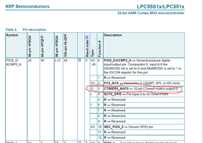
First of all, pls download data sheet of lpc5516 and check it in pin description. For example, the PIO0-0 can function as CTIMER0_MAT0, which means that the pin can function to output PWM signal.
PIO0_3 CTIMER0_MAT1
PIO0_5 CTIMER3_MAT0
PIO0_10 CTIMER2_MAT0
.....
In conclusion, all the CTIMERx_MATy pin can function as CTIMER PWM signal. In general, the MATCH0 register is used to configure the PWM period, so the CATIMERx_MAT0 is not used to output PWM. Of course, if you use the other match reg to control period, the MAT0 can be used to output PWM.
2)The SDK has example to have the CTIMER output PWM signal
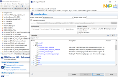
In the ctimer_PWM example, the PWM signal can output from PIO1_4 pin which multiplexed with CTIMER2_MAT1.
The example uses CTIMER2 MAT2, we use the follow Macro
#define CTIMER CTIMER2 /* Timer 2 */
#define CTIMER_MAT_OUT kCTIMER_Match_1 /* Match output 1 */
In the pin_mux.c file, the following is defined:
const uint32_t port1_pin4_config = (/* Pin is configured as CTIMER2_MAT1 */
IOCON_PIO_FUNC3 |
/* No addition pin function */
IOCON_PIO_MODE_INACT |
/* Standard mode, output slew rate control is enabled */
IOCON_PIO_SLEW_STANDARD |
/* Input function is not inverted */
IOCON_PIO_INV_DI |
/* Enables digital function */
IOCON_PIO_DIGITAL_EN |
/* Open drain is disabled */
IOCON_PIO_OPENDRAIN_DI);
/* PORT1 PIN4 (coords: 1) is configured as CTIMER2_MAT1 */
IOCON_PinMuxSet(IOCON, 1U, 4U, port1_pin4_config);
3)If you want to set the CTIMER2_MAT2 (pin PIO0_11) to output PWM. Pls try to use the code:
#define IOCON_PIO_FUNC2
const uint32_t port0_pin11_config = (/* Pin is configured as CTIMER2_MAT2 */
IOCON_PIO_FUNC2 |
/* No addition pin function */
IOCON_PIO_MODE_INACT |
/* Standard mode, output slew rate control is enabled */
IOCON_PIO_SLEW_STANDARD |
/* Input function is not inverted */
IOCON_PIO_INV_DI |
/* Enables digital function */
IOCON_PIO_DIGITAL_EN |
/* Open drain is disabled */
IOCON_PIO_OPENDRAIN_DI);
/* PORT0 PIN11 (coords: 1) is configured as CTIMER2_MAT2 */
IOCON_PinMuxSet(IOCON, 0U, 11U, port0_pin11_config);
In the main.c
#define CTIMER_MAT_OUT2 2
/* CTimer0 counter uses the AHB clock, some CTimer1 modules use the Aysnc clock */
srcClock_Hz = CTIMER_CLK_FREQ;
PRINTF("CTimer example to generate a PWM signal\r\n");
CTIMER_GetDefaultConfig(&config);
timerClock = srcClock_Hz / (config.prescale + 1);
CTIMER_Init(CTIMER, &config);
/* Get the PWM period match value and pulse width match value of 20Khz PWM signal with 20% dutycycle */
CTIMER_GetPwmPeriodValue(20000, 20, timerClock);
CTIMER_SetupPwmPeriod(CTIMER, CTIMER_MAT_PWM_PERIOD_CHANNEL, CTIMER_MAT_OUT, g_pwmPeriod, g_pulsePeriod, false);
CTIMER_SetupPwmPeriod(CTIMER, CTIMER_MAT_PWM_PERIOD_CHANNEL, CTIMER_MAT_OUT2, g_pwmPeriod, g_pulsePeriod, false);
CTIMER_StartTimer(CTIMER);
Pls have a try.
Hope it is helpful
BR
XiangJun Rong
- 新着としてマーク
- ブックマーク
- 購読
- ミュート
- RSS フィードを購読する
- ハイライト
- 印刷
- 不適切なコンテンツを報告
xiangjun_rong
- 新着としてマーク
- ブックマーク
- 購読
- ミュート
- RSS フィードを購読する
- ハイライト
- 印刷
- 不適切なコンテンツを報告
Hi,
First of all, pls download data sheet of lpc5516 and check it in pin description. For example, the PIO0-0 can function as CTIMER0_MAT0, which means that the pin can function to output PWM signal.
PIO0_3 CTIMER0_MAT1
PIO0_5 CTIMER3_MAT0
PIO0_10 CTIMER2_MAT0
.....
In conclusion, all the CTIMERx_MATy pin can function as CTIMER PWM signal. In general, the MATCH0 register is used to configure the PWM period, so the CATIMERx_MAT0 is not used to output PWM. Of course, if you use the other match reg to control period, the MAT0 can be used to output PWM.
2)The SDK has example to have the CTIMER output PWM signal
In the ctimer_PWM example, the PWM signal can output from PIO1_4 pin which multiplexed with CTIMER2_MAT1.
The example uses CTIMER2 MAT2, we use the follow Macro
#define CTIMER CTIMER2 /* Timer 2 */
#define CTIMER_MAT_OUT kCTIMER_Match_1 /* Match output 1 */
In the pin_mux.c file, the following is defined:
const uint32_t port1_pin4_config = (/* Pin is configured as CTIMER2_MAT1 */
IOCON_PIO_FUNC3 |
/* No addition pin function */
IOCON_PIO_MODE_INACT |
/* Standard mode, output slew rate control is enabled */
IOCON_PIO_SLEW_STANDARD |
/* Input function is not inverted */
IOCON_PIO_INV_DI |
/* Enables digital function */
IOCON_PIO_DIGITAL_EN |
/* Open drain is disabled */
IOCON_PIO_OPENDRAIN_DI);
/* PORT1 PIN4 (coords: 1) is configured as CTIMER2_MAT1 */
IOCON_PinMuxSet(IOCON, 1U, 4U, port1_pin4_config);
3)If you want to set the CTIMER2_MAT2 (pin PIO0_11) to output PWM. Pls try to use the code:
#define IOCON_PIO_FUNC2
const uint32_t port0_pin11_config = (/* Pin is configured as CTIMER2_MAT2 */
IOCON_PIO_FUNC2 |
/* No addition pin function */
IOCON_PIO_MODE_INACT |
/* Standard mode, output slew rate control is enabled */
IOCON_PIO_SLEW_STANDARD |
/* Input function is not inverted */
IOCON_PIO_INV_DI |
/* Enables digital function */
IOCON_PIO_DIGITAL_EN |
/* Open drain is disabled */
IOCON_PIO_OPENDRAIN_DI);
/* PORT0 PIN11 (coords: 1) is configured as CTIMER2_MAT2 */
IOCON_PinMuxSet(IOCON, 0U, 11U, port0_pin11_config);
In the main.c
#define CTIMER_MAT_OUT2 2
/* CTimer0 counter uses the AHB clock, some CTimer1 modules use the Aysnc clock */
srcClock_Hz = CTIMER_CLK_FREQ;
PRINTF("CTimer example to generate a PWM signal\r\n");
CTIMER_GetDefaultConfig(&config);
timerClock = srcClock_Hz / (config.prescale + 1);
CTIMER_Init(CTIMER, &config);
/* Get the PWM period match value and pulse width match value of 20Khz PWM signal with 20% dutycycle */
CTIMER_GetPwmPeriodValue(20000, 20, timerClock);
CTIMER_SetupPwmPeriod(CTIMER, CTIMER_MAT_PWM_PERIOD_CHANNEL, CTIMER_MAT_OUT, g_pwmPeriod, g_pulsePeriod, false);
CTIMER_SetupPwmPeriod(CTIMER, CTIMER_MAT_PWM_PERIOD_CHANNEL, CTIMER_MAT_OUT2, g_pwmPeriod, g_pulsePeriod, false);
CTIMER_StartTimer(CTIMER);
Pls have a try.
Hope it is helpful
BR
XiangJun Rong
- 新着としてマーク
- ブックマーク
- 購読
- ミュート
- RSS フィードを購読する
- ハイライト
- 印刷
- 不適切なコンテンツを報告
Dear Xiangjun,
I try to use the simple_pwm_interrupt demo to control the rgb led, how can I control the led on delay by the pwm cycle count insteal of the function bsp_delay_time.
Best Wish!
