
- Forums
- Product Forums
- General Purpose MicrocontrollersGeneral Purpose Microcontrollers
- i.MX Forumsi.MX Forums
- QorIQ Processing PlatformsQorIQ Processing Platforms
- Identification and SecurityIdentification and Security
- Power ManagementPower Management
- Wireless ConnectivityWireless Connectivity
- RFID / NFCRFID / NFC
- Advanced AnalogAdvanced Analog
- Neural Processing UnitsNeural Processing Units
- MCX Microcontrollers
- S32G
- S32K
- S32V
- MPC5xxx
- Other NXP Products
- S12 / MagniV Microcontrollers
- Powertrain and Electrification Analog Drivers
- Sensors
- Vybrid Processors
- Digital Signal Controllers
- 8-bit Microcontrollers
- ColdFire/68K Microcontrollers and Processors
- PowerQUICC Processors
- OSBDM and TBDML
- S32M
- S32Z/E
-
- Solution Forums
- Software Forums
- MCUXpresso Software and ToolsMCUXpresso Software and Tools
- CodeWarriorCodeWarrior
- MQX Software SolutionsMQX Software Solutions
- Model-Based Design Toolbox (MBDT)Model-Based Design Toolbox (MBDT)
- FreeMASTER
- eIQ Machine Learning Software
- Embedded Software and Tools Clinic
- S32 SDK
- S32 Design Studio
- GUI Guider
- Zephyr Project
- Voice Technology
- Application Software Packs
- Secure Provisioning SDK (SPSDK)
- Processor Expert Software
- Generative AI & LLMs
-
- Topics
- Mobile Robotics - Drones and RoversMobile Robotics - Drones and Rovers
- NXP Training ContentNXP Training Content
- University ProgramsUniversity Programs
- Rapid IoT
- NXP Designs
- SafeAssure-Community
- OSS Security & Maintenance
- Using Our Community
-
- Cloud Lab Forums
-
- Knowledge Bases
- ARM Microcontrollers
- i.MX Processors
- Identification and Security
- Model-Based Design Toolbox (MBDT)
- QorIQ Processing Platforms
- S32 Automotive Processing Platform
- Wireless Connectivity
- CodeWarrior
- MCUXpresso Suite of Software and Tools
- MQX Software Solutions
- RFID / NFC
- Advanced Analog
- Neural Processing Units
-
- NXP Tech Blogs
- Home
- :
- 汎用マイクロコントローラ
- :
- LPCマイクロコントローラ
- :
- LPCOpen master SPI on 5410x
LPCOpen master SPI on 5410x
- RSS フィードを購読する
- トピックを新着としてマーク
- トピックを既読としてマーク
- このトピックを現在のユーザーにフロートします
- ブックマーク
- 購読
- ミュート
- 印刷用ページ
LPCOpen master SPI on 5410x
- 新着としてマーク
- ブックマーク
- 購読
- ミュート
- RSS フィードを購読する
- ハイライト
- 印刷
- 不適切なコンテンツを報告
Hello,
I am trying to setup a simple master SPI interface on LPC54102 using LPCOpen. Following the examples, I use:
Chip_Clock_EnablePeriphClock(SYSCON_CLOCK_SPI0);
SPI_CFGSETUP_T spiSetup;
SPIM_DELAY_CONFIG_T masterDelay;
Chip_SPI_Init(LPC_SPIMASTERPORT);
Chip_SPI_Enable(LPC_SPIMASTERPORT);
spiSetup.master = 1;
spiSetup.lsbFirst = 0;
spiSetup.mode = SPI_CLOCK_MODE0;
Chip_SPI_ConfigureSPI(LPC_SPIMASTERPORT, &spiSetup);
Chip_SPI_SetCSPolLow(LPC_SPIMASTERPORT, 0);
Chip_SPIM_SetClockRate(LPC_SPIMASTERPORT, LPCMASTERCLOCKRATE);
masterDelay.PreDelay = 0x4;
masterDelay.PostDelay = 0x4;
masterDelay.FrameDelay = 0x4;
masterDelay.TransferDelay = 0x4;
Chip_SPIM_DelayConfig(LPC_SPIMASTERPORT, &masterDelay);
Chip_SPI_EnableInts(LPC_SPIMASTERPORT, (SPI_INTENSET_RXDYEN | SPI_INTENSET_SSDEN)); //???Needed?
NVIC_EnableIRQ(LPC_SPIMASTERIRQNUM);
spiMasterXfer.cbFunc = master_cb;
spiMasterXfer.state = SPIS_XFER_STATE_IDLE;
spiMasterXfer.txBuff = masterTXBuffer16;
spiMasterXfer.txCount = sizeof(masterTXBuffer16) / sizeof(uint16_t);/* Count is in transfer size */
spiMasterXfer.rxBuff = masterRXBuffer16;
spiMasterXfer.rxCount = sizeof(masterRXBuffer16) / sizeof(uint16_t);/* Count is in transfer size */
mstate = &spiMasterXfer.state;
spiMasterXfer.options = SPIM_XFER_OPTION_SIZE(16) | SPIM_XFER_OPTION_EOT | SPIM_XFER_OPTION_EOF;
spiMasterXfer.sselNum = 0;
masterTXBuffer16[0] = 0x1111;
Chip_GPIO_SetPinOutHigh(LPC_GPIO, 0, 19);
Chip_SPIM_XferBlocking(LPC_SPIMASTERPORT, &spiMasterXfer);
while (*mstate != SPIM_XFER_STATE_DONE) {
__NOP();
}
Chip_GPIO_SetPinOutLow(LPC_GPIO, 0, 19);
masterTXBuffer16[0] = 0x2222;
Chip_GPIO_SetPinOutHigh(LPC_GPIO, 0, 19);
Chip_SPIM_XferBlocking(LPC_SPIMASTERPORT, &spiMasterXfer);
while (*mstate != SPIM_XFER_STATE_DONE) {
__NOP();
}
Chip_GPIO_SetPinOutLow(LPC_GPIO, 0, 19);
To my surprise, I see the gpio toggling 4 times before even the first slave-select. The first word is sent (0x1111), then after a very long, unexplained delay also the second word comes (0x2222). There is no pulsing of the SlaveSelect signal in between, despite the
SPIM_XFER_OPTION_EOT | /* Enable this to assert and deassert SSEL for each individual byte/word */
Am I doing something inherently wrong?
Thank you for your support
- 新着としてマーク
- ブックマーク
- 購読
- ミュート
- RSS フィードを購読する
- ハイライト
- 印刷
- 不適切なコンテンツを報告
I still don't know if my configuration is wrong or if LPCOpen does not correctly support a simple blocking Master SPI read-write for this chip...
If anyone in the future runs into the same problem, the following works:
void spi_init(void) {
Chip_Clock_EnablePeriphClock(SYSCON_CLOCK_SPI0);
Chip_SYSCON_PeriphReset(RESET_SPI0);
LPC_SPIMASTERPORT->CFG = (SPI_CFG_MASTER_EN | SPI_CFG_SPI_EN);
LPC_SPIMASTERPORT->DLY = (SPI_DLY_PRE_DELAY(4) | SPI_DLY_POST_DELAY(4) | SPI_DLY_FRAME_DELAY(4) | SPI_DLY_TRANSFER_DELAY(4));
Chip_SPIM_SetClockRate(LPC_SPIMASTERPORT, LPCMASTERCLOCKRATE);
LPC_SPIMASTERPORT->TXCTRL = (SPI_TXCTL_EOT | SPI_TXCTL_EOF | SPI_TXCTL_FLEN(16));}
uint16_t spi_send_receive(uint16_t txdata) {
while (!(LPC_SPIMASTERPORT->STAT & SPI_STAT_TXRDY)) { __NOP(); }
LPC_SPIMASTERPORT->TXDAT = (uint32_t)txdata;
while ((!(LPC_SPIMASTERPORT->STAT & SPI_STAT_TXRDY))||(!(LPC_SPIMASTERPORT->STAT & SPI_STAT_RXRDY))) { __NOP(); }
return (uint16_t)((LPC_SPIMASTERPORT->RXDAT)&0xff);}
Without using interrupts or callbacks
- 新着としてマーク
- ブックマーク
- 購読
- ミュート
- RSS フィードを購読する
- ハイライト
- 印刷
- 不適切なコンテンツを報告
Hi Patroklos Anagonostou,
Sorry for my later reply!
I have test the lpcopen spi master in my LPCXpresso 54102 board, the GPIO PIO0_19 can track the SPI wave correctly.
This is my logic analyzer SPI wave

Clock rate is 4Mhz.

My modified code is lpc5410x_xpresso54102_keil_iar_v3.03.000_16, project periph_spi_sm_int.
Main code is :
int main(void)
{
int loop = 1; /* Prevents unreachable statement warning */
uint16_t seed = 0;
volatile uint8_t *mstate, *sstate;
SystemCoreClockUpdate();
Board_Init();
Chip_GPIO_SetPinDIROutput(LPC_GPIO, 0, 19);
Chip_GPIO_SetPinState(LPC_GPIO, 0, 19, true);
Chip_GPIO_SetPinOutHigh(LPC_GPIO, 0, 19);
/* SPI initialization */
Init_SPI_PinMux();
/* Initialize stopwatch driver so some event times can be measured */
StopWatch_Init();
/* Setup SPI controllers */
setupMaster();
setupSlave();
/* Enable SPI controller interrupts */
NVIC_EnableIRQ(LPC_SPIMASTERIRQNUM);
NVIC_EnableIRQ(LPC_SPISLAVEIRQNUM);
DEBUGOUT("SPI master/slave combined example\r\n");
/* Loop forever */
while (loop) {
/* Setup some data for transmit from master to slave and slave to master */
seed = bufferInit(seed);
masterTXBuffer16[0] = 0X1111;
masterTXBuffer16[1] = 0X2222;
/* Set master transfer, this is only the initial trasnfer, the callbacks can
change this later */
spiMasterXfer.cbFunc = master_cb;
spiMasterXfer.state = SPIS_XFER_STATE_IDLE;
spiMasterXfer.txBuff = masterTXBuffer16;
spiMasterXfer.txCount = 1;/* Count is in transfer size */
spiMasterXfer.rxBuff = masterRXBuffer16;
spiMasterXfer.rxCount = 1;/* Count is in transfer size */
mstate = &spiMasterXfer.state;
/* Setup master trasnfer options - 16 data bits per transfer, EOT, EOF */
spiMasterXfer.options =
SPIM_XFER_OPTION_SIZE(16) | /* This must be enabled as a minimum, use 16 data bits */
SPIM_XFER_OPTION_EOT | /* Enable this to assert and deassert SSEL for each individual byte/word, current slave functions for this example do not support this */
SPIM_XFER_OPTION_EOF | /* Insert a delay between bytes/words as defined by frame delay time */
0;
/* Use SPI select 0 */
spiMasterXfer.sselNum = 0;
/* Time master and slave transfers */
masterTime = StopWatch_Start();
/* Limitation: The call below 'pre-buffers' the initial slave transmit datum.
If this isn't pre-buffered, a slave transmit underflow will always occur
at slave assertion time for the initial transmit datum. The datum sent to the
master will be 0. This is ok as we are only using a single slave, but with multiple
slaves pre-buffering is not always an option and the master might need to toss the
first byte. */
Chip_SPI_FlushFifos(LPC_SPIMASTERPORT);
Chip_GPIO_SetPinOutHigh(LPC_GPIO, 0, 19);
/* Start master transfer */
Chip_SPIM_Xfer(LPC_SPIMASTERPORT, &spiMasterXfer);
/* Sleep until transfers are complete */
while ((*mstate != SPIM_XFER_STATE_DONE) ) {
//__WFI();
}
Chip_GPIO_SetPinOutLow(LPC_GPIO, 0, 19);
//===============================
spiMasterXfer.cbFunc = master_cb;
spiMasterXfer.state = SPIS_XFER_STATE_IDLE;
spiMasterXfer.txBuff = masterTXBuffer16+1;
spiMasterXfer.txCount = 1;/* Count is in transfer size */
spiMasterXfer.rxBuff = masterRXBuffer16;
spiMasterXfer.rxCount = 1;/* Count is in transfer size */
mstate = &spiMasterXfer.state;
/* Setup master trasnfer options - 16 data bits per transfer, EOT, EOF */
spiMasterXfer.options =
SPIM_XFER_OPTION_SIZE(16) | /* This must be enabled as a minimum, use 16 data bits */
SPIM_XFER_OPTION_EOT | /* Enable this to assert and deassert SSEL for each individual byte/word, current slave functions for this example do not support this */
SPIM_XFER_OPTION_EOF | /* Insert a delay between bytes/words as defined by frame delay time */
0;
/* Use SPI select 0 */
spiMasterXfer.sselNum = 0;
/* Time master and slave transfers */
masterTime = StopWatch_Start();
/* Limitation: The call below 'pre-buffers' the initial slave transmit datum.
If this isn't pre-buffered, a slave transmit underflow will always occur
at slave assertion time for the initial transmit datum. The datum sent to the
master will be 0. This is ok as we are only using a single slave, but with multiple
slaves pre-buffering is not always an option and the master might need to toss the
first byte. */
Chip_SPI_FlushFifos(LPC_SPIMASTERPORT);
Chip_GPIO_SetPinOutHigh(LPC_GPIO, 0, 19);
/* Start master transfer */
Chip_SPIM_Xfer(LPC_SPIMASTERPORT, &spiMasterXfer);
/* Sleep until transfers are complete */
while ((*mstate != SPIM_XFER_STATE_DONE) ) {
//__WFI();
}
Chip_GPIO_SetPinOutLow(LPC_GPIO, 0, 19);
/* Toggle LED */
Board_LED_Toggle(0);
while (Board_UARTGetChar() == EOF) {}
}
return 0;
}
I also attached my spi_sm_int.c file for your reference.
You can try my code on your side.
Have a great day,
Kerry
-----------------------------------------------------------------------------------------------------------------------
Note: If this post answers your question, please click the Correct Answer button. Thank you!
-----------------------------------------------------------------------------------------------------------------------
- 新着としてマーク
- ブックマーク
- 購読
- ミュート
- RSS フィードを購読する
- ハイライト
- 印刷
- 不適切なコンテンツを報告
Hi Patroklos Anagnostou,
Could you please also attach your SPI wave? Just for analysis.
Have a great day,
Kerry
-----------------------------------------------------------------------------------------------------------------------
Note: If this post answers your question, please click the Correct Answer button. Thank you!
-----------------------------------------------------------------------------------------------------------------------
- 新着としてマーク
- ブックマーク
- 購読
- ミュート
- RSS フィードを購読する
- ハイライト
- 印刷
- 不適切なコンテンツを報告
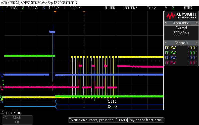
Yes, please find attached the case with spi clock 1Mhz and the case with 100kHz.
The blue trace is the gpio that tracks the code execution flow, the green is the slave select, the yellow is clock and the pink is data. It seems to me that the spi functions are not blocking and the state is 'DONE' even during the transfer. Also in the case of 1Mhz the EOF flag to pulse the SS between byte/words is ignored.