
- Forums
- Product Forums
- General Purpose MicrocontrollersGeneral Purpose Microcontrollers
- i.MX Forumsi.MX Forums
- QorIQ Processing PlatformsQorIQ Processing Platforms
- Identification and SecurityIdentification and Security
- Power ManagementPower Management
- Wireless ConnectivityWireless Connectivity
- RFID / NFCRFID / NFC
- Advanced AnalogAdvanced Analog
- Neural Processing UnitsNeural Processing Units
- MCX Microcontrollers
- S32G
- S32K
- S32V
- MPC5xxx
- Other NXP Products
- S12 / MagniV Microcontrollers
- Powertrain and Electrification Analog Drivers
- Sensors
- Vybrid Processors
- Digital Signal Controllers
- 8-bit Microcontrollers
- ColdFire/68K Microcontrollers and Processors
- PowerQUICC Processors
- OSBDM and TBDML
- S32M
- S32Z/E
-
- Solution Forums
- Software Forums
- MCUXpresso Software and ToolsMCUXpresso Software and Tools
- CodeWarriorCodeWarrior
- MQX Software SolutionsMQX Software Solutions
- Model-Based Design Toolbox (MBDT)Model-Based Design Toolbox (MBDT)
- FreeMASTER
- eIQ Machine Learning Software
- Embedded Software and Tools Clinic
- S32 SDK
- S32 Design Studio
- GUI Guider
- Zephyr Project
- Voice Technology
- Application Software Packs
- Secure Provisioning SDK (SPSDK)
- Processor Expert Software
- Generative AI & LLMs
-
- Topics
- Mobile Robotics - Drones and RoversMobile Robotics - Drones and Rovers
- NXP Training ContentNXP Training Content
- University ProgramsUniversity Programs
- Rapid IoT
- NXP Designs
- SafeAssure-Community
- OSS Security & Maintenance
- Using Our Community
-
- Cloud Lab Forums
-
- Knowledge Bases
- ARM Microcontrollers
- i.MX Processors
- Identification and Security
- Model-Based Design Toolbox (MBDT)
- QorIQ Processing Platforms
- S32 Automotive Processing Platform
- Wireless Connectivity
- CodeWarrior
- MCUXpresso Suite of Software and Tools
- MQX Software Solutions
- RFID / NFC
- Advanced Analog
- Neural Processing Units
-
- NXP Tech Blogs
- Home
- :
- General Purpose Microcontrollers
- :
- LPC Microcontrollers
- :
- Re: LPC54018 USART Flexcomm4 non 3.3V logic
LPC54018 USART Flexcomm4 non 3.3V logic
- Subscribe to RSS Feed
- Mark Topic as New
- Mark Topic as Read
- Float this Topic for Current User
- Bookmark
- Subscribe
- Mute
- Printer Friendly Page
LPC54018 USART Flexcomm4 non 3.3V logic
- Mark as New
- Bookmark
- Subscribe
- Mute
- Subscribe to RSS Feed
- Permalink
- Report Inappropriate Content
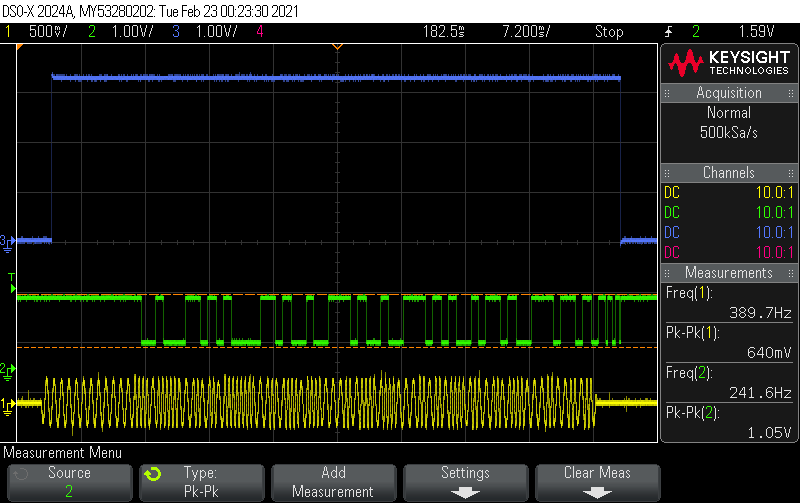
I'm using the LPC54018 IOT Module along with the mini base board. I'm currently trying to initiate a UART communication at 1200 baud rate for communication with an external HART modem. For some reason, when I connect P3_26 (port 3 pin 26) to the external HART modem, the GPIO logic is not 0-3.3V, but some lesser peak to peak voltage. When I disconnect this pin from the external device, the oscilloscope shows 0-3.3V as normal. So the issue seems to be coming from the peripheral on the LPC54018.
What could be the issue that is causing this? The TX seems to be working fine. The LPC is able to send out 0-3.3V uart signals and my external device receives it correctly.
The green is the uart signal on the RXD pin (port 3 pin 26). The yellow is the modem's HART signal which represents the data being sent, and the green is the Modem's demodulator which converts that signal to uart. The blue is just a detection signal that is HIGH whenever there is a HART signal.
- Mark as New
- Bookmark
- Subscribe
- Mute
- Subscribe to RSS Feed
- Permalink
- Report Inappropriate Content
Hello ,
P3_26 is the RX of UART, so I think first you need confirm the signal logic from HART module.
And what about the blue signal meaning?
BR
Alice
- Mark as New
- Bookmark
- Subscribe
- Mute
- Subscribe to RSS Feed
- Permalink
- Report Inappropriate Content
I now tried a different USART peripheral (P3_21) and also removed the external HART module, and I'm still seeing that the USART communication is not at 0-3.3V. I believe the way I'm initializing the USART peripheral may not be accurate.Can you please confirm if I am initializing my Flexomm4 peripheral properly?
I'm starting with the "lpc5018iotmodule_usart_interrupt_transfer" example from the SDK and making modifications to it.
1. Initialized Flexcomm4 as USART in pinmux.c : I inserted these two lines in "BOARD_InitPins():
const uint32_t port3_pin26_config = (
IOCON_PIO_FUNC3 | /* Pin is configured as FC4_RXD_SDA_MOSI */
IOCON_PIO_MODE_INACT | /* No addition pin function */
IOCON_PIO_INV_DI | /* Input function is not inverted */
IOCON_PIO_DIGITAL_EN | /* Enables digital function */
IOCON_PIO_INPFILT_OFF | /* Input filter disabled */
IOCON_PIO_SLEW_STANDARD | /* Standard mode, output slew rate control is enabled */
IOCON_PIO_OPENDRAIN_DI /* Open drain is disabled */
);
IOCON_PinMuxSet(IOCON, PORT3_IDX, PIN26_IDX, port3_pin26_config); /* PORT3 PIN26 */
const uint32_t port3_pin27_config = (
IOCON_PIO_FUNC3 | /* Pin is configured as FC4_TXD_SCL_MISO */
IOCON_PIO_MODE_INACT | /* No addition pin function */
IOCON_PIO_INV_DI | /* Input function is not inverted */
IOCON_PIO_DIGITAL_EN | /* Enables digital function */
IOCON_PIO_INPFILT_OFF | /* Input filter disabled */
IOCON_PIO_SLEW_STANDARD | /* Standard mode, output slew rate control is enabled */
IOCON_PIO_OPENDRAIN_DI /* Open drain is disabled */
);
IOCON_PinMuxSet(IOCON, PORT3_IDX, PIN27_IDX, port3_pin27_config); /* PORT3 PIN27 */
2: In board.h I defined the following variables (basically changed the default "0s" to "4"):
#define BOARD_DEBUG_UART_BASEADDR (uint32_t) USART4
#define BOARD_DEBUG_UART_INSTANCE 4U
#define BOARD_DEBUG_UART_CLK_FREQ CLOCK_GetFlexCommClkFreq(0U)
#define BOARD_DEBUG_UART_CLK_ATTACH kFRO12M_to_FLEXCOMM4
#define BOARD_DEBUG_UART_RST kFC4_RST_SHIFT_RSTn
#define BOARD_UART_IRQ_HANDLER FLEXCOMM4_IRQHandler
#define BOARD_UART_IRQ FLEXCOMM4_IRQn
3: In usart_interrupt_transfer.c: I made the following definitions
#define DEMO_USART USART4
#define DEMO_USART_CLK_FREQ CLOCK_GetFlexCommClkFreq(4U)
4: In main() I commented out "BOARD_InitDebugConsole()"
It seems to me like the way I'm configuring the peripheral is incorrect and thus is causing a change in logic levels. Can you confirm my procedure is correct for initializing FlexComm4 for USART operation?
- Mark as New
- Bookmark
- Subscribe
- Mute
- Subscribe to RSS Feed
- Permalink
- Report Inappropriate Content
Did you call the appropriate fsl function for the peripheral, e.g. FLEXCOMM_Init() ?
I would take a flexcomm SDK example, and compare with this code.
- Mark as New
- Bookmark
- Subscribe
- Mute
- Subscribe to RSS Feed
- Permalink
- Report Inappropriate Content
I managed to correct the issue on P3_21 so I will use that. P3_26 Which is Flexcomm 4 still produces issues. The issue is not with the external HART module. I have certified that it is 0-3.3V compatible.
I do have another question. Since I am using baudrate of 1200 for my communication, what is the best clock source to use for the USART? Is it ok to use the 12MHz source clock our is it better to use 32kHz RTC/ something else?
- Mark as New
- Bookmark
- Subscribe
- Mute
- Subscribe to RSS Feed
- Permalink
- Report Inappropriate Content
Hello,
Yes, 12MHZ source clock is OK.
Regards,
Alice
- Mark as New
- Bookmark
- Subscribe
- Mute
- Subscribe to RSS Feed
- Permalink
- Report Inappropriate Content
> ...so I think first you need confirm the signal logic from HART module.
I definitely agree.
First check the datasheet of the module, if the signal levels are compatible with the MCU. Perhaps the HART module is 1,8V logic ...