
- Forums
- Product Forums
- General Purpose MicrocontrollersGeneral Purpose Microcontrollers
- i.MX Forumsi.MX Forums
- QorIQ Processing PlatformsQorIQ Processing Platforms
- Identification and SecurityIdentification and Security
- Power ManagementPower Management
- Wireless ConnectivityWireless Connectivity
- RFID / NFCRFID / NFC
- Advanced AnalogAdvanced Analog
- Neural Processing UnitsNeural Processing Units
- MCX Microcontrollers
- S32G
- S32K
- S32V
- MPC5xxx
- Other NXP Products
- S12 / MagniV Microcontrollers
- Powertrain and Electrification Analog Drivers
- Sensors
- Vybrid Processors
- Digital Signal Controllers
- 8-bit Microcontrollers
- ColdFire/68K Microcontrollers and Processors
- PowerQUICC Processors
- OSBDM and TBDML
- S32M
- S32Z/E
-
- Solution Forums
- Software Forums
- MCUXpresso Software and ToolsMCUXpresso Software and Tools
- CodeWarriorCodeWarrior
- MQX Software SolutionsMQX Software Solutions
- Model-Based Design Toolbox (MBDT)Model-Based Design Toolbox (MBDT)
- FreeMASTER
- eIQ Machine Learning Software
- Embedded Software and Tools Clinic
- S32 SDK
- S32 Design Studio
- GUI Guider
- Zephyr Project
- Voice Technology
- Application Software Packs
- Secure Provisioning SDK (SPSDK)
- Processor Expert Software
- Generative AI & LLMs
-
- Topics
- Mobile Robotics - Drones and RoversMobile Robotics - Drones and Rovers
- NXP Training ContentNXP Training Content
- University ProgramsUniversity Programs
- Rapid IoT
- NXP Designs
- SafeAssure-Community
- OSS Security & Maintenance
- Using Our Community
-
- Cloud Lab Forums
-
- Knowledge Bases
- ARM Microcontrollers
- i.MX Processors
- Identification and Security
- Model-Based Design Toolbox (MBDT)
- QorIQ Processing Platforms
- S32 Automotive Processing Platform
- Wireless Connectivity
- CodeWarrior
- MCUXpresso Suite of Software and Tools
- MQX Software Solutions
- RFID / NFC
- Advanced Analog
- Neural Processing Units
-
- NXP Tech Blogs
- Home
- :
- 汎用マイクロコントローラ
- :
- LPCマイクロコントローラ
- :
- Re: LCP54628 MCAN Configuration
LCP54628 MCAN Configuration
- RSS フィードを購読する
- トピックを新着としてマーク
- トピックを既読としてマーク
- このトピックを現在のユーザーにフロートします
- ブックマーク
- 購読
- ミュート
- 印刷用ページ
LCP54628 MCAN Configuration
- 新着としてマーク
- ブックマーク
- 購読
- ミュート
- RSS フィードを購読する
- ハイライト
- 印刷
- 不適切なコンテンツを報告
Hello!
Please, someone could help me with CAN protocol configuration?
In this project I am using OM13098 development board with LPC54628 microcontroller and I'm working with MCUXpressoIDE v11.6.0 and with version 2.12 from SDK.
I saw and compiled the examples from SDK, but I think there is something weird with that examples.
I'm trying to do a loopback teste with the CAN Protocol, but following example code (lpcxpresso54628_mcan_loopback) is possible do this loopback without phisical connection beteween CAN0_RD (RX) and CAN0_TD (TX). In this way, isn't useful for one real application. It's right?
I expect to develop a example code with CAN0 working by interruptions and just works when I'll physically connect RX with TX like in serial communication.
In future, I intend to develop a master CAN with CAN1 and a slave CAN with CAN0.
Below there is the example code who I'm using and trying to unveil this mystery. If someone could help me, please could you contact me?
- 新着としてマーク
- ブックマーク
- 購読
- ミュート
- RSS フィードを購読する
- ハイライト
- 印刷
- 不適切なコンテンツを報告
Hello @FFOXZ
About external loopback mode, please refer to UM10912 -> 5.14.1.7.1 External loop back mode, after configure based on loopback demo,
if still can't work, you can use peripheral tool to configure as below:

BR
Alice
- 新着としてマーク
- ブックマーク
- 購読
- ミュート
- RSS フィードを購読する
- ハイライト
- 印刷
- 不適切なコンテンツを報告
Hello @Alice_Yang !!!
I really need to say thank you for your advice. I read the documentation and now I could understand how this examples works.
But my idea is using the CAN RX with the CAN TX outside of microcontroller, work like a real external loop back and don't have a "jumper" inside of microcontroller like this tests modes.
Please, could you know a way to do this? Do you know a way to disable this "jumper" and I could read the real data what I transfer?
For example: I send eight equals data (0x55) and read the same data on CAN RX.
Below is the same photo as I send to @frank_m to be more explained what I want to do.
- 新着としてマーク
- ブックマーク
- 購読
- ミュート
- RSS フィードを購読する
- ハイライト
- 印刷
- 不適切なコンテンツを報告
Hello @FFOXZ
The term "loopback" here is a special term for CAN specification, which mean's do not need external connection.
If you want a actual external CAN test, which MUST need CAN transceiver and another CAN node for test. you can use some "USB-CAN" adapter to try this.It is not possible to connect directly CAN_TX and CAN RX for on-board CAN test.
BR
Alice
- 新着としてマーク
- ブックマーク
- 購読
- ミュート
- RSS フィードを購読する
- ハイライト
- 印刷
- 不適切なコンテンツを報告
Hello @Alice_Yang !!!
Thank you again for answer me.
Really?? Yesterday I was trying to use the example mcan_interrupt_transfer to try again another test join CAN_RX and CAN_TX directly, like I said before. My oscilloscope show me all transmitted package but in debug mode appear this error 0x1849 --> kStatus_MCAN_UnHandled.
Excuse me but I'll insist a little bit... But it CAN protocol is similar to Serial communication, isn't?
More one doubt... So, in same board, I could do this external test with both CAN's? For example, I can connect the CAN_0 with the CAN_1, using transceivers.
Could I use this mcan_interrupt_transfer example for this test?
Tks,
Cvsta.
- 新着としてマーク
- ブックマーク
- 購読
- ミュート
- RSS フィードを購読する
- ハイライト
- 印刷
- 不適切なコンテンツを報告
Hello @FFOXZ
1) "More one doubt... So, in same board, I could do this external test with both CAN's? For example, I can connect the CAN_0 with the CAN_1, using transceivers."
->> Yes.
2)There is a description about CAN transceiver:

BR
Alice
- 新着としてマーク
- ブックマーク
- 購読
- ミュート
- RSS フィードを購読する
- ハイライト
- 印刷
- 不適切なコンテンツを報告
Hi @Alice_Yang
This description about CAN Transceiver as you send is from a public document?
Would it be possible for you to share this document?
Tks,
CVSta
- 新着としてマーク
- ブックマーク
- 購読
- ミュート
- RSS フィードを購読する
- ハイライト
- 印刷
- 不適切なコンテンツを報告
Hello @FFOXZ
I think you are going to the wrong way if you still want do not use transceiver.
You can check CAN protocol about detail, and for your final application, two CAN nodes and transceiver are needed.
Sorry I didn't remember where the description come from.
BR
Alice
- 新着としてマーク
- ブックマーク
- 購読
- ミュート
- RSS フィードを購読する
- ハイライト
- 印刷
- 不適切なコンテンツを報告
Hello @Alice_Yang !
Sorry for the delay in answering you, but I was developing the code that I had previously commented based on the last messages. However I believe I didn't make it clear what problem I'm having here and we're going in another direction, so I'll try to explain again with more information.
I'm trying to connect MCANTX with MCANRX on CAN0 on the same OM13098 board. Because I only have one board.
My configuration is set up like this:
1 cable connected to CAN0_TD - Port 3 Pin 18 (coords: M6).
1 cable connected to CAN0_RD - Port 3 Pin 19 (coords: J3).
1 cable connected to GND.
1 USB cable connected to the J8 connector for DEBUG.
The cables of pins P3-18 and P3-19 are jumpered so that the data transfer from the TX port is received by the RX port. This jumper is being carried out by the oscilloscope probe, where I can read the packet I am sending.
I'm using the mcan_loopback example and I'm sending the following packet through MCANTX_0 straight to MCANRX_0 on the same OM13098 board.
Package: 0x55, 0x55, 0x55, 0x55, 0x55, 0x55, 0x55, 0x55;
Remembering that I am not doing the loopback of the balanced pair (after the transducers), but the loopback of the digital pair.
In this example I commented out the line that indicates the loopback ("mcanConfig.enableLoopBackExt = true") and I am using CAN Open in normal operation, considering the following defines below.
#define USE_CANFD     (0U)
#define DLC           (8)
#define BYTES_IN_MB   kMCAN_8ByteDatafield
#define CAN_DATASIZE  (8U)
On the oscilloscope (Photo OSCSCREEN_MCAN0), I can see that some communication between the RX/TX has taken place because the CAN packet is fully described on the bus.
Except in the serial terminal, I don't get the printfs saying the packet was sent. And, in DEBUG mode, it indicates that the code is looping the while of the MCAN_TransferSendBlocking(EXAMPLE_MCAN, 0, &txFrame) function. As if waiting for the message to be sent.
I am also sending the photos of the CAN0 registers when it is "stuck" inside that while. I don't know if this can help.
Thanks.
Best Regards.
- 新着としてマーク
- ブックマーク
- 購読
- ミュート
- RSS フィードを購読する
- ハイライト
- 印刷
- 不適切なコンテンツを報告
As mentioned, I am lacking specific experience with the LPC CAN_FD peripheral.
But I would check the error counter values after (each) transmission attempt. At the LPC54xxx, this is ECR (offset 0x40).
> And, in DEBUG mode, it indicates that the code is looping the while of the MCAN_TransferSendBlocking(EXAMPLE_MCAN, 0, &txFrame) function. As if waiting for the message to be sent.
I would add this error counter check in said while loop.
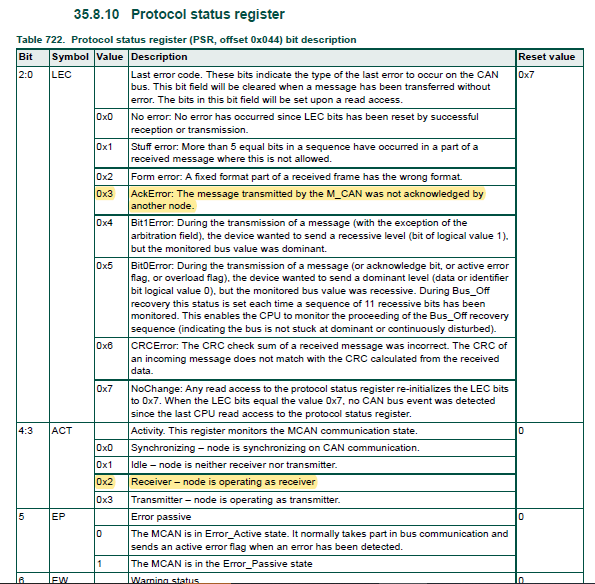
And if the TEC/REC counter go up, I would check that status register (PSR, offset 0x44). It should perhaps give you a hint what went wrong.
By the way, a "send" is never executed immediately (like on RS232 or SPI), because CAN is an arbitrated multi-user bus. All CAN peripherals have queues or "message boxes" that perform the transmit independantly as soon as the bus is free.
- 新着としてマーク
- ブックマーク
- 購読
- ミュート
- RSS フィードを購読する
- ハイライト
- 印刷
- 不適切なコンテンツを報告
Hello @frank_m !
My problem here is happening in main before the main loop (while(1)), you could see this in my first post.
And in my last post, I put the value of registers there.
And the ECR is with of 128 value.I saw in user manual it represents an error level, but I didn't understand what is meaning.
And the PSR presents of 1915 value, what represents AckError and is the receiver node.
In pictures below, I post this results. Please, could you can see the pisctures? And I would like to know if this is what you were talking about?
- 新着としてマーク
- ブックマーク
- 購読
- ミュート
- RSS フィードを購読する
- ハイライト
- 印刷
- 不適切なコンテンツを報告
> In pictures below, I post this results. Please, could you can see the pisctures? And I would like to know if this is what you were talking about?
Basically yes, this is what I meant.
But as said, I am not really familiar with the LPC CAN peripheral.
As I undersood it, you connected two separate CAN peripherals, right ?
There is no Rx and Tx line on a CAN bus (i.e. after the transceiver), but only CANH and CANL. Which means there is no real synchronous transmission. AFAIK each node internally "receives" it's own transmissions anyway, and checks it back, especially in the arbitration phase. Thus a loopback mode on a single CAN unit will most probably not work, and NXP implemented special IP features to provide said internal loopback mode without requiring a connection.
If you use two peripherals, you will need to initialize them for identical bus parameters, especially baudrate.
The AckError flag says that no node acknowledged the reception.
- 新着としてマーク
- ブックマーク
- 購読
- ミュート
- RSS フィードを購読する
- ハイライト
- 印刷
- 不適切なコンテンツを報告
Hello @frank_m !
>As I undersood it, you connected two separate CAN peripherals, right ?
I think you could didn't understood correctly. Because I'm using the same CAN0, connecting the TX with RX. Like I said before, I'm trying to read the digital par not the balanced par.
Reading all documentations I understand you cannot connect CANH with CANL, but I don't understand why you cannot connect CAN RX with CAN TX.
- 新着としてマーク
- ブックマーク
- 購読
- ミュート
- RSS フィードを購読する
- ハイライト
- 印刷
- 不適切なコンテンツを報告
On the physical CAN bus, there are three connections : GND, CANH and CANL.
At rest, CANH and CANL are at the same voltage level. The actual signal is differential, i.e. the bit value is represented by the voltage difference between CANH and CANL.
This in turn means, there is no direct relation between CANH and CANL on the bus side, and CAN-Tx and CAN-Rx on the MCU side. The CAN bus does not allow synchronous transmissions SPI or RS232, only one node can transmit at any time.
Thus I think every node (like the CAN peripheral unit on the LPC54xxx) is blanking out Rx internally while it is transmitting (Tx).
Which means, you usually cannot bridge Tx and Rx, and expect it to work.
That dawned on my only yesterday. Since I have quite a lot actual CAN devices at my disposal here, I hardly ever played with internal loopback modes.
The CAN peripheral unit of the LPC54xxx obviously contains provisions to "shortcut" the physical pins (Tx and Rx), which allows for a direct reception of "transmitted" messages". This is mentzioned internal loopback mode.
I think you will need a second CAN node.
This could be a CAN adapter for the PC (USB-CAN), or the second CAN peripheral of the MCU. The LPC54628 has two CAN units.
USB-CAN adapters have only CAN bus level outputs, so you would need transceivers for your MCU side.
In case you use CAN0 and CAN1 of the MCU, you could make direct TTL level connections (CAN0-Tx with CAN1-Rx and vice versa).
- 新着としてマーク
- ブックマーク
- 購読
- ミュート
- RSS フィードを購読する
- ハイライト
- 印刷
- 不適切なコンテンツを報告
> And the ECR is with of 128 value.I saw in user manual it represents an error level, but I didn't understand what is meaning.
These error counter are basically CAN standard behavior, understandably NXP is not repeating it in it's MCU user manuals. Here e.g. one internet site : https://www.csselectronics.com/pages/can-bus-errors-intro-tutorial
Upon Tx or Rx errors, a node is counting said values (in ECR) up. Once it reaches a first threshold, usually 128, it goes into "passive mode" (does not send anymore). If further errors happen, the node goes eventually into "bus off" mode, so as to not block the whole bus.
Successful transmissions/receptions decrease the counter, and one erraneous frame increases the count by more than 1 (if I remember correctly, usually 5).
For the error flags, I would need to look at it first.
- 新着としてマーク
- ブックマーク
- 購読
- ミュート
- RSS フィードを購読する
- ハイライト
- 印刷
- 不適切なコンテンツを報告
Hello @Alice_Yang !!!
Thank you again for more this documentation.
Now I'll try develop a new test using CAN_0 with CAN_1 and publish my code here as soon as possible.
More one question, I saw there is a software Can Open File Player. It is necessary to read CAN package? Or there is another software necesary to read CAN package?
Best Regards.
Cvsta.
- 新着としてマーク
- ブックマーク
- 購読
- ミュート
- RSS フィードを購読する
- ハイライト
- 印刷
- 不適切なコンテンツを報告
> More one question, I saw there is a software Can Open File Player. It is necessary to read CAN package? Or there is another software necesary to read CAN package?
CANopen is a standard based on CAN, restricting epsecially the ID usage. https://en.wikipedia.org/wiki/CANopen
Unless you don't have a CANopen environment (and don't plan on using one), I would not start with those examples. They add another layer of complexity.
I used to work a lot with such CANopen devices in my company.
In regards to mentioned CAN breakout boards, me and Alice_Yang were speaking about different things.
Those breakout boards mentioned by me are for the MCU side, and would extend any eval board.
An USB CAN adapter is useful/required for the host/PC side.
My company uses a few Vector pods, but mostly the cheaper PCAN devices : https://www.peak-system.com/PCAN-USB.199.0.html?&L=1
- 新着としてマーク
- ブックマーク
- 購読
- ミュート
- RSS フィードを購読する
- ハイライト
- 印刷
- 不適切なコンテンツを報告
Hello @frank_m
Thank you to send me all this links and information about USB CAN.
But thinking better I won't need to use these softwares or CAN breakout boards.
Because, my ideia is connect one board CAN Master with another board CAN Slave. So I think just testing the connection and sending a package and receiving the same package will be successfully.
Tks.
CVSta
- 新着としてマーク
- ブックマーク
- 購読
- ミュート
- RSS フィードを購読する
- ハイライト
- 印刷
- 不適切なコンテンツを報告
Hello @FFOXZ
1) "More one question, I saw there is a software Can Open File Player. It is necessary to read CAN package? Or there is another software necesary to read CAN package?"
->> Do you mean a PC software? connect with "USB-CAN" adapter?
For start, if you only have one board, as Frank said, you can consider "relatively cheap CAN breakout boards available, like in the Arduino/maker scene. Those would be a great start to get a prototype working, because very few evaluation boards come with CAN hardware.".
Or use "USB-CAN" adapter.
2)If you use "mcan_interrupt_transfer" demo, there is hardware requirements and boards setting in readme.txt:

BR
Alice
- 新着としてマーク
- ブックマーク
- 購読
- ミュート
- RSS フィードを購読する
- ハイライト
- 印刷
- 不適切なコンテンツを報告
> Excuse me but I'll insist a little bit... But it CAN protocol is similar to Serial communication, isn't?
You are right, at this level, CAN is just a digital signal like RS232 or SPI.
You can connect two nodes directly, provided they have the same digital levels and specifications (and the cable is not too long).
By the way, I think there are several relatively cheap CAN breakout boards available, like in the Arduino/maker scene. Those would be a great start to get a prototype working, because very few evaluation boards come with CAN hardware.
- 新着としてマーク
- ブックマーク
- 購読
- ミュート
- RSS フィードを購読する
- ハイライト
- 印刷
- 不適切なコンテンツを報告
There is a "mcan_interrupt_transfer" example in driver_examples in the SDK.
I am referring to the LPCXpresso54628 SDK here which I use occasionally.
Though I must admit I never tried any CAN example with this board.
To use CAN (not the internal loopback mode), you should have proper transceivers attached, albeit for just two nodes, a direct (TTL level) connection might work.
Or, you can try to modify your loopback example, and initialize the CAN peripheral in full CAN mode.
Perhaps taking the code from the interrupt_transfer example as template.
By the way, I had included a CANopen middleware package in my SDK, which provides 4 CANopen examples. Not sure if that would be helpful for you.
My company's products use mainly CANopen for their ECUs.