
- Forums
- Product Forums
- General Purpose MicrocontrollersGeneral Purpose Microcontrollers
- i.MX Forumsi.MX Forums
- QorIQ Processing PlatformsQorIQ Processing Platforms
- Identification and SecurityIdentification and Security
- Power ManagementPower Management
- Wireless ConnectivityWireless Connectivity
- RFID / NFCRFID / NFC
- Advanced AnalogAdvanced Analog
- Neural Processing UnitsNeural Processing Units
- MCX Microcontrollers
- S32G
- S32K
- S32V
- MPC5xxx
- Other NXP Products
- S12 / MagniV Microcontrollers
- Powertrain and Electrification Analog Drivers
- Sensors
- Vybrid Processors
- Digital Signal Controllers
- 8-bit Microcontrollers
- ColdFire/68K Microcontrollers and Processors
- PowerQUICC Processors
- OSBDM and TBDML
- S32M
- S32Z/E
-
- Solution Forums
- Software Forums
- MCUXpresso Software and ToolsMCUXpresso Software and Tools
- CodeWarriorCodeWarrior
- MQX Software SolutionsMQX Software Solutions
- Model-Based Design Toolbox (MBDT)Model-Based Design Toolbox (MBDT)
- FreeMASTER
- eIQ Machine Learning Software
- Embedded Software and Tools Clinic
- S32 SDK
- S32 Design Studio
- GUI Guider
- Zephyr Project
- Voice Technology
- Application Software Packs
- Secure Provisioning SDK (SPSDK)
- Processor Expert Software
- Generative AI & LLMs
-
- Topics
- Mobile Robotics - Drones and RoversMobile Robotics - Drones and Rovers
- NXP Training ContentNXP Training Content
- University ProgramsUniversity Programs
- Rapid IoT
- NXP Designs
- SafeAssure-Community
- OSS Security & Maintenance
- Using Our Community
-
- Cloud Lab Forums
-
- Knowledge Bases
- ARM Microcontrollers
- i.MX Processors
- Identification and Security
- Model-Based Design Toolbox (MBDT)
- QorIQ Processing Platforms
- S32 Automotive Processing Platform
- Wireless Connectivity
- CodeWarrior
- MCUXpresso Suite of Software and Tools
- MQX Software Solutions
- RFID / NFC
- Advanced Analog
- Neural Processing Units
-
- NXP Tech Blogs

Board LPCS5506 dev kit
I'm using 4 wire fan, Power, ground, TACH, and PWM.
For PWM I'm using Ctimer2 Mat 3 in PWM mode.. Timer clock is 16MHz, PWM period is 1KHz, Duty cycled at 20%.
That's working as expected.
I Intend to use Ctimer0 in Capture Mode on channel 0 to count the fan rotations, and measure the RPM. What's the best way to do this, I have implemented it but it's behaving rather weirdly.
I've configured ctimer0 at 1KHz to count the fan signals (2 rising and 2 falling make a rotation)
const ctimer_config_t CTIMER0_FAN_TACH_config = {

  .mode = kCTIMER_TimerMode,

  .input = kCTIMER_Capture_0,

  .prescale = 15999

};

static void CTIMER0_FAN_TACH_init(void) {

  /* CTIMER0 peripheral initialization */

  CTIMER_Init(CTIMER0_FAN_TACH_PERIPHERAL, &CTIMER0_FAN_TACH_config);

  /* capture channel 0 of CTIMER0 peripheral initialization */

  CTIMER_SetupCapture(CTIMER0_FAN_TACH_PERIPHERAL, CTIMER0_FAN_TACH_CAPTURE_0_CHANNEL, kCTIMER_Capture_BothEdge, true);

  CTIMER_RegisterCallBack(CTIMER0_FAN_TACH_PERIPHERAL, CTIMER0_FAN_TACH_callback, kCTIMER_SingleCallback);

  /* Start the timer */

  CTIMER_StartTimer(CTIMER0_FAN_TACH_PERIPHERAL);

}
I'm getting interrupts randomly, and they stop abruptly.
I get interrupts even without the fan connected. What am I missing ?
已解决! 转到解答。

 xiangjun_rong
Hi,
Can you share the motor type for example, DC, BLDC, PMSM,SR or stepper?
BTW, you use capture function of CTimer, can you tell us what the capturing signal is? is it from encoder or whatever so that the signal can represents the motor position or motor position change?
BR
XiangJun Rong
https://products.sanyodenki.com/info/sanace/en/technical_material/dcsensor.html
9GX3612P3K001
TACH Pulse out is the signal type..
For setting up the capture, what should the timer clock be ? I set it up the same as the BOARD_BootClock
at 16MHz and adjusted the prescaler to be 16000 s.t the timer freq is 1 KHz. Lmk if this is incorrect
xiangjun_rong
Hi,
As you know that there are two methods to measure the motor speed. One is to measure the signal number in a fixed time, the method adapts to high speed motor, for your application, you can connect the tach sensor signal to the capture pin of CTimer, the CTimer will count the tach sensor signal as tick, you can have the MRT or whatever timer to generate an interrupt in a fixed cycle time, in the ISR, you can read the CTimer counter to know that how many signal are generated, in this way, you can get the speed of motor, you can compute the speed with the formula:
counter number/fixed cycle time
Another method is the one you are using, you use the CTimer capture function, for your case, the CTimer counts the 1KHZ tick, when a capture event happens, an interrupt is triggered, in the ISR, you can compute the difference between two consecutive events and compute the speed with the formula:
1/[reading difference*(tick cycle)]
BTW, the signal connected to CTimer capture pin can function as either tick or capturing signal depending your configuration.
Hope it can help you
BR
XiangJun Rong
Thanks for the response.. Yes I'm using the second method, where the TACH signal is connected to the capture pin (not sure if it has to be a particular channel).. But as you can see, the initialization code above is how I've set it up..
void fan_tach_isr(uint32_t flags)
{
	static int8_t count = 1;
	uint8_t tc_read_count = 4; //4 poles for the fan = 1 rotation
	uint32_t tc = CTIMER_GetTimerCountValue(g_ctx.fanCtrlHandle.tach_ctimer_handle);

	if(++count > tc_read_count)
	{
		//uint32_t tc = CTIMER_GetTimerCountValue(g_ctx.fanCtrlHandle.tach_ctimer_handle);
		g_ctx.fanCtrlHandle.rpm = (60000/tc);
		CTIMER_Reset(g_ctx.fanCtrlHandle.tach_ctimer_handle);
		LOG_DEBUG("ISR count = %d, TC = %ld RPM = %ld", count, tc, g_ctx.fanCtrlHandle.rpm);
		count = 1;
	}
}
where tach_timer_handle is
CTIMER0_FAN_TACH_PERIPHERALThe interrupts are firing only when I connect and disconnect, and they're weird.. as in the TC field in the handle keeps increasing even when the fan is disconnected - (this may be expected? )
and the interrupts don't fire when the fan is running after a few rounds.. not sure what's going on here! any ideas ?
Btw, I'm using Ctimer2 to control the PWM pin on the same fan.. The config for that looks like this:
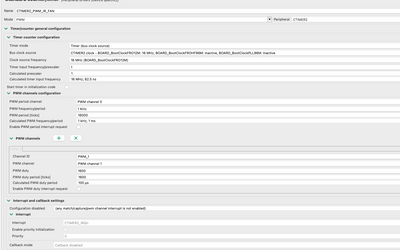
and the corresponding Tach pin to ctimer0, and the config looks like this:
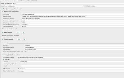
Does it look okay ? or am I missing something ?
Thanks for the response.. Yes I'm using the second method, where the TACH signal is connected to the capture pin (not sure if it has to be a particular channel).. But as you can see, the initialization code above is how I've set it up..
void fan_tach_isr(uint32_t flags)
{
	static int8_t count = 1;
	uint8_t tc_read_count = 4; //4 poles for the fan = 1 rotation
	uint32_t tc = CTIMER_GetTimerCountValue(g_ctx.fanCtrlHandle.tach_ctimer_handle);

	if(++count > tc_read_count)
	{
		//uint32_t tc = CTIMER_GetTimerCountValue(g_ctx.fanCtrlHandle.tach_ctimer_handle);
		g_ctx.fanCtrlHandle.rpm = (60000/tc);
		CTIMER_Reset(g_ctx.fanCtrlHandle.tach_ctimer_handle);
		LOG_DEBUG("ISR count = %d, TC = %ld RPM = %ld", count, tc, g_ctx.fanCtrlHandle.rpm);
		count = 1;
	}
}
where tach_timer_handle is
CTIMER0_FAN_TACH_PERIPHERALThe interrupts are firing only when I connect and disconnect, and they're weird.. as in the TC field in the handle keeps increasing even when the fan is disconnected - (this may be expected? )
and the interrupts don't fire when the fan is running after a few rounds.. not sure what's going on here! any ideas ?
xiangjun_rong
Hi,
Can you estimate the TACH signal frequency when the motor is running?
I suppose that the TACH signal frequency is too high, the capture frequency is too high for the MCU to handle. The maximum ISR frequency is 1MHz I suppose for the lpc550x.
For your case, pls delete the line in the ISR:
LOG_DEBUG("ISR count = %d, TC = %ld RPM = %ld", count, tc, g_ctx.fanCtrlHandle.rpm);
Because the line requires long time, instead, you can save the tc to an array, in the debug, you can check the data in the array.
Can you use the method one? you can have the CTimer to count the edge of the capture signal if the TACH signal frequency is very high, pls have a try.
BR
XiangJun Rong
