
- Forums
- Product Forums
- General Purpose MicrocontrollersGeneral Purpose Microcontrollers
- i.MX Forumsi.MX Forums
- QorIQ Processing PlatformsQorIQ Processing Platforms
- Identification and SecurityIdentification and Security
- Power ManagementPower Management
- Wireless ConnectivityWireless Connectivity
- RFID / NFCRFID / NFC
- Advanced AnalogAdvanced Analog
- Neural Processing UnitsNeural Processing Units
- MCX Microcontrollers
- S32G
- S32K
- S32V
- MPC5xxx
- Other NXP Products
- S12 / MagniV Microcontrollers
- Powertrain and Electrification Analog Drivers
- Sensors
- Vybrid Processors
- Digital Signal Controllers
- 8-bit Microcontrollers
- ColdFire/68K Microcontrollers and Processors
- PowerQUICC Processors
- OSBDM and TBDML
- S32M
- S32Z/E
-
- Solution Forums
- Software Forums
- MCUXpresso Software and ToolsMCUXpresso Software and Tools
- CodeWarriorCodeWarrior
- MQX Software SolutionsMQX Software Solutions
- Model-Based Design Toolbox (MBDT)Model-Based Design Toolbox (MBDT)
- FreeMASTER
- eIQ Machine Learning Software
- Embedded Software and Tools Clinic
- S32 SDK
- S32 Design Studio
- GUI Guider
- Zephyr Project
- Voice Technology
- Application Software Packs
- Secure Provisioning SDK (SPSDK)
- Processor Expert Software
- Generative AI & LLMs
-
- Topics
- Mobile Robotics - Drones and RoversMobile Robotics - Drones and Rovers
- NXP Training ContentNXP Training Content
- University ProgramsUniversity Programs
- Rapid IoT
- NXP Designs
- SafeAssure-Community
- OSS Security & Maintenance
- Using Our Community
-
- Cloud Lab Forums
-
- Knowledge Bases
- ARM Microcontrollers
- i.MX Processors
- Identification and Security
- Model-Based Design Toolbox (MBDT)
- QorIQ Processing Platforms
- S32 Automotive Processing Platform
- Wireless Connectivity
- CodeWarrior
- MCUXpresso Suite of Software and Tools
- MQX Software Solutions
- RFID / NFC
- Advanced Analog
- Neural Processing Units
-
- NXP Tech Blogs
- Home
- :
- ARM Microcontrollers
- :
- LPC Microcontrollers Knowledge Base
- :
- How to boot from the external flash for LPC54018
How to boot from the external flash for LPC54018
- Subscribe to RSS Feed
- Mark as New
- Mark as Read
- Bookmark
- Subscribe
- Printer Friendly Page
- Report Inappropriate Content
How to boot from the external flash for LPC54018
How to boot from the external flash for LPC54018
In recent years of MCU technology evolving, booting from the external flash seems to become more and more popular, actually, LPC already has employed this technology for many years.
NXP's recently released the LPC540xx family which continues the trend of high-performance flash-less MCU.

The developers may be a bit confused with the external FLASH which is used for storing the program, as they are used to directly using the internal FLASH for programming and debugging the chip. But, don't worry, let me introduce it in the following sections.
- LPC54018's three ways of loading program
In general, RAM stores data, however, RAM can also store programs. In previous projects, we occasionally move some key functions in RAM in order to improve the execution speed of these programs. The current implementation is to put all the programs in RAM more thoroughly. Based on this idea, you can directly use the debugger to load the executable image into the on-chip RAM and this method is called RAM TARGET.
After downloading the executable program image file to the external flash, when the bootloader loads the complete image to on-chip RAM to run, the method is called the Plain Load Image method.
Actually, both of these above ideas are routine, chip designers have also created a "super-capability" that allows the chip to directly execute external FLASH programs (Execute In Place, XIP). With this 'superpower', no matter whether the program boot from the external FLASH or the internal FLASH, there is no difference in operating performance.
The RAM TARGET method mentioned above is only suitable for debugging the application. Once the chip is powered off or reset, the downloaded program in the RAM will disappear. Meanwhile, the size of the RAM also give some restrictions for debugging.
In the Plain Load and XIP modes, the executable image file is stored in the external flash. After MCU is powered, the bootloader which is resided in ROM copies the first 512 bytes from the image (vector components and image header) into internal SRAMX at location 0x0000 0000 to validate the vector table and image header to confirm the booting mode. And the program will not be lost after power-off or reset. Fig1 illustrates the boot process of LPC54018.

Fig1 LPC54018 boot process flow
- Experiment show
Board: LPCXpresso54018 board (OM40003)
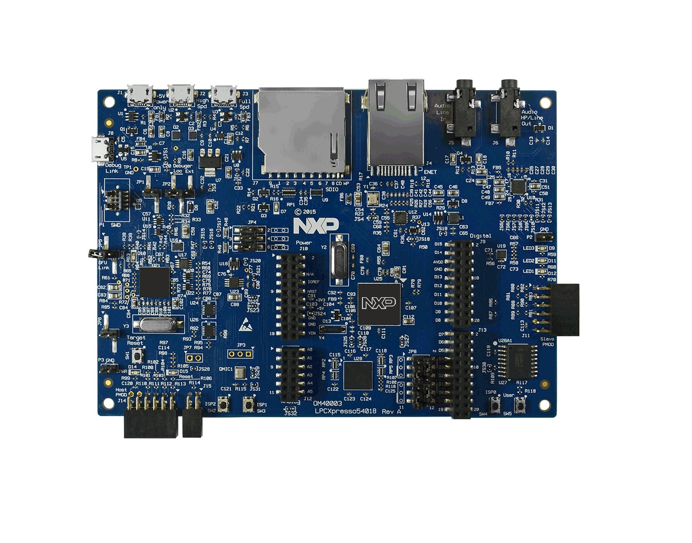
Fig1 LPCXpresso54018 board
Demo code: Hello world (From the SDK), modifying the hello world code in below way, which points out the load program way and date time.
PRINTF("hello world. XXXXXXXX \r\n");
PRINTF("hello world, %s, %s.\r\n", __DATE__, __TIME__);- Experiment 1: RAM Target
Demo code: Hello world (From the SDK), modifying the hello world code in below way.
PRINTF("hello world. RAM Target \r\n");
PRINTF("hello world, %s, %s.\r\n", __DATE__, __TIME__); Note: Setting the Reset: Core when debugging the demo

Fig2 Setting the Reset: Core
Running testing:
As the Fig3 illustrates, it would print the below message when debugging the demo, however, after reset, it would run the plain load image which is programmed before, as the RAM lost the hello world demo.

Fig3 RAM Target runing testing
- Experiment 2: Plain Load Image
Demo code: Hello world (From the SDK), modifying the hello world code in below way.
PRINTF("hello world. PLAIN LOAD IMAGE \r\n");
PRINTF("hello world, %s, %s.\r\n", __DATE__, __TIME__); Download image to external flash:
1. Build the demo to generate a bin file.
This plainload example linked the vector table to 0x00000000, but program to external flash 0x10000000.
2. Program the bin file to external on board flash via SEGGER J-FLASH Lite(V6.22 or higher):
a. Open SEGGER J-FLASH Lite, select device LPC54018.
b. Click the 'Erase Chip' to erase the extrenal flash.(if can not success, press SW4 button and reset the board, and try to erase again)
Note: if can not success( press SW4 and reset the board, and try to erase again)

Fig4 Erase the external flash
c. Select the bin data file, set the '.bin/Erase Start' address to 0x10000000, then click 'Program Device'

Fig5 Program the external flash
Running testing:
Fig6 illustrates the result of running the plain load image.

Fig6 Plain load image runing testing
- Experiment 3: XIP Image
Demo code: Hello world qspi_xip (From the SDK), modifying the code in below way.
PRINTF("hello world. PLAIN LOAD IMAGE \r\n");
PRINTF("hello world, %s, %s.\r\n", __DATE__, __TIME__); Download image to external flash:
1. Build the demo to generate a bin file.
2. Program the bin file to external on board flash via SEGGER J-FLASH Lite(V6.22 or higher):
a. Open SEGGER J-FLASH Lite, select device LPC54018.
b. Click the 'Erase Chip' to erase the extrenal flash.(if can not success, press SW4 button and reset the board, and try to erase again)
Note: if can not success( press SW4 and reset the board, and try to erase again)

Fig7 Erase the external flash
c. Select the bin data file, set the '.bin/Erase Start' address to 0x10000000, then click 'Program Device'

Fig8 Program the external flash
Running testing:
Fig9 illustrates the result of running the plain load image.

Fig9 XIP image runing testing