
- Forums
- Product Forums
- General Purpose MicrocontrollersGeneral Purpose Microcontrollers
- i.MX Forumsi.MX Forums
- QorIQ Processing PlatformsQorIQ Processing Platforms
- Identification and SecurityIdentification and Security
- Power ManagementPower Management
- Wireless ConnectivityWireless Connectivity
- RFID / NFCRFID / NFC
- Advanced AnalogAdvanced Analog
- Neural Processing UnitsNeural Processing Units
- MCX Microcontrollers
- S32G
- S32K
- S32V
- MPC5xxx
- Other NXP Products
- S12 / MagniV Microcontrollers
- Powertrain and Electrification Analog Drivers
- Sensors
- Vybrid Processors
- Digital Signal Controllers
- 8-bit Microcontrollers
- ColdFire/68K Microcontrollers and Processors
- PowerQUICC Processors
- OSBDM and TBDML
- S32M
- S32Z/E
-
- Solution Forums
- Software Forums
- MCUXpresso Software and ToolsMCUXpresso Software and Tools
- CodeWarriorCodeWarrior
- MQX Software SolutionsMQX Software Solutions
- Model-Based Design Toolbox (MBDT)Model-Based Design Toolbox (MBDT)
- FreeMASTER
- eIQ Machine Learning Software
- Embedded Software and Tools Clinic
- S32 SDK
- S32 Design Studio
- GUI Guider
- Zephyr Project
- Voice Technology
- Application Software Packs
- Secure Provisioning SDK (SPSDK)
- Processor Expert Software
- Generative AI & LLMs
-
- Topics
- Mobile Robotics - Drones and RoversMobile Robotics - Drones and Rovers
- NXP Training ContentNXP Training Content
- University ProgramsUniversity Programs
- Rapid IoT
- NXP Designs
- SafeAssure-Community
- OSS Security & Maintenance
- Using Our Community
-
- Cloud Lab Forums
-
- Knowledge Bases
- ARM Microcontrollers
- i.MX Processors
- Identification and Security
- Model-Based Design Toolbox (MBDT)
- QorIQ Processing Platforms
- S32 Automotive Processing Platform
- Wireless Connectivity
- CodeWarrior
- MCUXpresso Suite of Software and Tools
- MQX Software Solutions
- RFID / NFC
- Advanced Analog
- Neural Processing Units
-
- NXP Tech Blogs
- Home
- :
- 汎用マイクロコントローラ
- :
- Kinetisマイクロコントローラ
- :
- K64F ADC code limit
K64F ADC code limit
- RSS フィードを購読する
- トピックを新着としてマーク
- トピックを既読としてマーク
- このトピックを現在のユーザーにフロートします
- ブックマーク
- 購読
- ミュート
- 印刷用ページ
- 新着としてマーク
- ブックマーク
- 購読
- ミュート
- RSS フィードを購読する
- ハイライト
- 印刷
- 不適切なコンテンツを報告
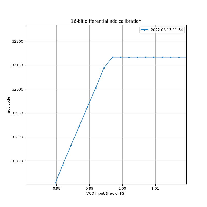
I am finding that the on-chip ADC of the K64F saturates before its full-scale input. I am using ADC0 of the MK64FN1M0VMD12, configured for differential 16-bit, with VREFH = 3.3 V nominal (3.296 V measured), VREFL = 0 V, and measuring the adc code as a function of input voltage. Results are attached. As you can see, the adc code saturates at about 32133, or about 98% of full-scale. (I trust the x-axis values to about 10 ppm). Per the spec sheet, I expect up to about 6 LSBs of full-scale error, but this is quite a bit more than that. Is this a known issue with the on-chip ADC?
解決済! 解決策の投稿を見る。
- 新着としてマーク
- ブックマーク
- 購読
- ミュート
- RSS フィードを購読する
- ハイライト
- 印刷
- 不適切なコンテンツを報告
Hi,
Not sure if it is relevant, but I believe the ADC16 is much the same implementation across all Kinetis devices. One thing that is different in the data sheet for MK22FN256VLL12 is that input range, Vadin is VREFL to 31/32 * VREFH when operating in 16-bit differential modes, and VREFL to VREFH in other modes. Also, no specifications for full scale error in more than 12 bit range.
Would it be possible for you try try single-ended mode to see if this improves linearity in the upper range?
Kind regards,
Troels
- 新着としてマーク
- ブックマーク
- 購読
- ミュート
- RSS フィードを購読する
- ハイライト
- 印刷
- 不適切なコンテンツを報告
I went ahead and configured the ADC for SE measurement. This does appear to fix the linearity issue and extends the usable range all the way to VREFH.
.png")
I believe the K64 Data Sheet should be updated to state that the usable range for differential measurements is reduced to 31/32*VREFH (or whatever the appropriate fraction is. Not sure where 31/32 comes from, since the ADC is 16-bit).

- 新着としてマーク
- ブックマーク
- 購読
- ミュート
- RSS フィードを購読する
- ハイライト
- 印刷
- 不適切なコンテンツを報告
Hi @aberger
Thank you so much for using our community, and thanks a lot for your patience too, we have some backlog due the high number of requests.
Regarding your question, it is unclear to me what do you refer about with "the x-axis values to about 10ppm" ? And then, may you share with me a screenshot from the data that your are seeing on the data sheet, please? Because I do not know well what is the issue that you are having.
Hope you may help me with that information, I will be more than happy to continue assisting you.
Please let me know if you have more questions.
Thank you in advance.
Best Regards.
Pablo Avalos.
- 新着としてマーク
- ブックマーク
- 購読
- ミュート
- RSS フィードを購読する
- ハイライト
- 印刷
- 不適切なコンテンツを報告
Hi Pablo,
Thank you for coming around to this.
A graph of adc code vs input voltage is attached to the original post. I will re-attach it here as well. The input voltage plotted on the x-axis is separately measured with a Keysight 33465A, so I trust the measurements to about 10 parts-per-million (ppm), or 0.001%. The values are normalized to the full-scale input of 3.3 V (so that an x-axis value of 1.00 corresponds to 3.3 V).
You can see from the attached figure that the maximum adc code is 32133, even when the input voltage is at or exceeds full-scale. However, I would expect a maximum code of 32767. Therefore, the saturated value of 32133 corresponding to about 2% error when supplying full-scale input. The ADC specification suggests about 6 LSBs of full-scale error (or 0.02% error).
I have also separately measured VREFH, and found this to be 3.296 V, or about 99.88% of 3.3 V nominal. This simply means that the adc should return 32767 (full-scale) when the input voltage is at 3.296 V (x-axis is at 0.9988 instead of 1.00).
- 新着としてマーク
- ブックマーク
- 購読
- ミュート
- RSS フィードを購読する
- ハイライト
- 印刷
- 不適切なコンテンツを報告
Hi @aberger
I really appreciate that you were so patient. Our backlog increased a lot due positive covid tests at the office. Please accept my apologies for late response.
After double checking your issue on what you are trying to understand, I think you are wrong when you say "The ADC specification suggests about 6 LSBs of full-scale error (or 0.02% error).", because checking the Reference Manual you can see the following:

Based on this, you will need to consider that the difference between your conversion code width when you have maximum voltage (measured 3.296V) and the ideal code width (1 LSB = 3.3V) is the one that is going to be used, and that's why you see 32133 as your maximum code.
Hope this is helpful, please let me know your comments or if you have more questions.
Best Regards.
Pablo Avalos.
- 新着としてマーク
- ブックマーク
- 購読
- ミュート
- RSS フィードを購読する
- ハイライト
- 印刷
- 不適切なコンテンツを報告
I'm sorry, I don't follow either the language of the manual or your explanation. Full-scale error is typically defined as the overall error between an ideal ADC response and the actual ADC response when the input voltage is at its maximum.
Below is another measured ADC transfer function (on a different unit, but which shows the same qualitative behavior). Now I am plotting the x-axis in units of V, and I provide the measured value of VREFH as a dashed line for reference (VREFH = 3.3015 V in this example, and is the same as VDDA).
You can see that the ADC output code hits a limit of 32148 when the input reaches 3.24 V, or 98% of the full-scale range. The ideal ADC code is shown in orange, reaching (2^15 - 1) at input = VREFH. This corresponds to a full-scale error (by my understanding) of 32767 - 32148 = 619 LSBs.
