- NXP Forums
- Product Forums
- General Purpose MicrocontrollersGeneral Purpose Microcontrollers
- i.MX Forumsi.MX Forums
- QorIQ Processing PlatformsQorIQ Processing Platforms
- Identification and SecurityIdentification and Security
- Power ManagementPower Management
- MCX Microcontrollers
- S32G
- S32K
- S32V
- MPC5xxx
- Other NXP Products
- Wireless Connectivity
- S12 / MagniV Microcontrollers
- Powertrain and Electrification Analog Drivers
- Sensors
- Vybrid Processors
- Digital Signal Controllers
- 8-bit Microcontrollers
- ColdFire/68K Microcontrollers and Processors
- PowerQUICC Processors
- OSBDM and TBDML
-
- Solution Forums
- Software Forums
- MCUXpresso Software and ToolsMCUXpresso Software and Tools
- CodeWarriorCodeWarrior
- MQX Software SolutionsMQX Software Solutions
- Model-Based Design Toolbox (MBDT)Model-Based Design Toolbox (MBDT)
- FreeMASTER
- eIQ Machine Learning Software
- Embedded Software and Tools Clinic
- S32 SDK
- S32 Design Studio
- Vigiles
- GUI Guider
- Zephyr Project
- Voice Technology
- Application Software Packs
- Secure Provisioning SDK (SPSDK)
- Processor Expert Software
-
- Topics
- Mobile Robotics - Drones and RoversMobile Robotics - Drones and Rovers
- NXP Training ContentNXP Training Content
- University ProgramsUniversity Programs
- Rapid IoT
- NXP Designs
- SafeAssure-Community
- OSS Security & Maintenance
- Using Our Community
-
- Cloud Lab Forums
-
- Home
- :
- General Purpose Microcontrollers
- :
- Kinetis Microcontrollers
- :
- Re: FRDMK64F internal ADC is Giving Non-Linear Data??
FRDMK64F internal ADC is Giving Non-Linear Data??
- Subscribe to RSS Feed
- Mark Topic as New
- Mark Topic as Read
- Float this Topic for Current User
- Bookmark
- Subscribe
- Mute
- Printer Friendly Page
FRDMK64F internal ADC is Giving Non-Linear Data??
- Mark as New
- Bookmark
- Subscribe
- Mute
- Subscribe to RSS Feed
- Permalink
- Report Inappropriate Content
Hello Everyone!
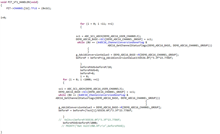
I am working on Battery Management System (BMS), where I need Open circuit Voltage measurement (OCV) of the battery to be measured in real time. I have sensing circuit based on resistive voltage divider. I am measuring the OCV simply with internal ADC (16 bits) of FRDMK64F. But the problem i am facing is ADC is giving me non-Linear data for corresponding input from sensor output. I have check my sensing circuit voltage input (Regulated input Power supply) and output, its linear. But the ADC Data I am getting is not linear w.r.t sensing circuit output voltage and power supply. I have attached my codes for OCV measurement, Voltages (Power supply, sensing circuit, and FRDMk64F calculated) and ADC data. Also the corresponding plot of Power supply voltage and ADC data w.r.t sensing circuit voltage are attached.
(1)
********************************************************************************************************************
(2)
*******************************************************************************************************************
(3)
**********************************************************************************************************************
(4)
- Mark as New
- Bookmark
- Subscribe
- Mute
- Subscribe to RSS Feed
- Permalink
- Report Inappropriate Content
Without knowing the DSP chip I can't say anything there, other than I'm surprised it worked.
The impedance of that circuit is far to high to get good results with most any of the on board ADCs.
I'm surprised that the results you got are even as good as you showed.
Add a Rail-To-Rail OpAmp Follower at TP10.
On the output of the Follower put a 47 ohm resistor and a 22 pF to 47 pF cap.
The resistor is to prevent instability from driving a capacitive load.
The capacitor swamps out the internal switched capacitance to give a more stable load.
It will also from a second low pass filter in this case.
- Mark as New
- Bookmark
- Subscribe
- Mute
- Subscribe to RSS Feed
- Permalink
- Report Inappropriate Content
"I have sensing circuit based on resistive voltage divider. "
Is it just a voltage divider hooked to the ADC pins?
If so that will not work well.
The ADC input is a complex switched capacitance network impedance.
There needs to be an OpAmp buffer if you don't have one.
Analog Devices has some good application notes and tutorials, which are in their Seminar series.
- Mark as New
- Bookmark
- Subscribe
- Mute
- Subscribe to RSS Feed
- Permalink
- Report Inappropriate Content
First of all thank you for your response. Here are my schematics for the Voltage sensing circuit. Voltage divider circuit followed by Low pass pass filter. It is been used in various application (with DSPs) for voltage sensing. But I am using it first time with FRDMK64F.


