
- Forums
- Product Forums
- General Purpose MicrocontrollersGeneral Purpose Microcontrollers
- i.MX Forumsi.MX Forums
- QorIQ Processing PlatformsQorIQ Processing Platforms
- Identification and SecurityIdentification and Security
- Power ManagementPower Management
- Wireless ConnectivityWireless Connectivity
- RFID / NFCRFID / NFC
- Advanced AnalogAdvanced Analog
- Neural Processing UnitsNeural Processing Units
- MCX Microcontrollers
- S32G
- S32K
- S32V
- MPC5xxx
- Other NXP Products
- S12 / MagniV Microcontrollers
- Powertrain and Electrification Analog Drivers
- Sensors
- Vybrid Processors
- Digital Signal Controllers
- 8-bit Microcontrollers
- ColdFire/68K Microcontrollers and Processors
- PowerQUICC Processors
- OSBDM and TBDML
- S32M
- S32Z/E
-
- Solution Forums
- Software Forums
- MCUXpresso Software and ToolsMCUXpresso Software and Tools
- CodeWarriorCodeWarrior
- MQX Software SolutionsMQX Software Solutions
- Model-Based Design Toolbox (MBDT)Model-Based Design Toolbox (MBDT)
- FreeMASTER
- eIQ Machine Learning Software
- Embedded Software and Tools Clinic
- S32 SDK
- S32 Design Studio
- GUI Guider
- Zephyr Project
- Voice Technology
- Application Software Packs
- Secure Provisioning SDK (SPSDK)
- Processor Expert Software
- Generative AI & LLMs
-
- Topics
- Mobile Robotics - Drones and RoversMobile Robotics - Drones and Rovers
- NXP Training ContentNXP Training Content
- University ProgramsUniversity Programs
- Rapid IoT
- NXP Designs
- SafeAssure-Community
- OSS Security & Maintenance
- Using Our Community
-
- Cloud Lab Forums
-
- Knowledge Bases
- ARM Microcontrollers
- i.MX Processors
- Identification and Security
- Model-Based Design Toolbox (MBDT)
- QorIQ Processing Platforms
- S32 Automotive Processing Platform
- Wireless Connectivity
- CodeWarrior
- MCUXpresso Suite of Software and Tools
- MQX Software Solutions
- RFID / NFC
- Advanced Analog
- Neural Processing Units
-
- NXP Tech Blogs
- Home
- :
- 汎用マイクロコントローラ
- :
- Kinetisマイクロコントローラ
- :
- Re: Cannot enter background mode.
Cannot enter background mode.
- RSS フィードを購読する
- トピックを新着としてマーク
- トピックを既読としてマーク
- このトピックを現在のユーザーにフロートします
- ブックマーク
- 購読
- ミュート
- 印刷用ページ
- 新着としてマーク
- ブックマーク
- 購読
- ミュート
- RSS フィードを購読する
- ハイライト
- 印刷
- 不適切なコンテンツを報告
I'm using KDS 2.0.0 with a MK60FN1M part and a Universal Multilink FX on my own PCB. My board worked fine with KDS 1.1.1. I upgraded to KDS 2.0.0, and now get the dreaded "Cannot enter background mode. Check connections." I tried running KDS 1.1.1 with the same results. I added the 50ms delay after reset before communicating to target with no improvement. Tried creating a new project with the same results.
Downloaded CW 10.6 and made a new project. This works. Tried going back to KDS and got same error.
Anybody have any ideas? I'm dead in the water.
Thanks,
Don
解決済! 解決策の投稿を見る。
- 新着としてマーク
- ブックマーク
- 購読
- ミュート
- RSS フィードを購読する
- ハイライト
- 印刷
- 不適切なコンテンツを報告
OK, I finally found the problem. I won't bore you with the details, but somehow my virtual machine decided to reset the USB settings to use USB 1.1 instead of 2.0. I don't know why CW worked OK, but my test project is now debugging with KDS 2.0. I will next try my original project and see if it has returned from the dead.
Thanks everybody for trying to help and I'm sorry for wasting your time.
Don
- 新着としてマーク
- ブックマーク
- 購読
- ミュート
- RSS フィードを購読する
- ハイライト
- 印刷
- 不適切なコンテンツを報告
Everyone, my Kinetis project is still dead. I was forced to move to another project while in waiting.
Anybody have suggestions?
- 新着としてマーク
- ブックマーク
- 購読
- ミュート
- RSS フィードを購読する
- ハイライト
- 印刷
- 不適切なコンテンツを報告
Hey - I have the same problem, and this fixed it!
Set mem inaccessible-by-default on (default was off).
I also set "Force thread list update on suspend." I don't think it matters.

For those of you new to the Multilink - there are some gotchas I received my first P&E Multilink today. First time I used it - hooking to a FRDM-K64F.
The drivers are there, but directories are honked up. C:\PEMicro\multilink_universal\Drivers_11_1_1\windriver (and osbdm) are both the same.
I ended up copying all the files up from the redist and then the installer would run. Also, I finally found the documentation (which does not discuss the above) in
C:\PEMicro\multilink_universal\PE4576 - Technical Summary for Multilink Universal and Multilink Universal FX.pdf
Also - J11 should not be cut I got a little chop happy. Also, I later changed the Debug Shift Frequency to 2000 (2MHz) and it works.
As other folks have mentioned, life is better if you cycle power to your target before debugging.
Also, I plug into the non-SDA USB connector to power the FRDM-K64F.
I also removed C55 (reset line cap) as others have suggested. I don't know if this is required or not.
EDIT : I was unable to get the debugger to work in JTAG mode, had to use SWD. Just looked at the schematic of the FRDM-K64F and it is just a SWD interface.
It's a bit frustrating, but it does work. I've only single stepped, not really fiddled with registers yet.
EDIT: Also, if any of this is wrong, please post. I was hacking at a solution quickly and haven't worked out why the SDA needs to be in the loop (J11). I'm betting that cutting that trace removes a pullup which is required. (Just a guess).
QUESTION(s):
J25 - what should it be set to? I have the reset jumper (J25) set to pins 2-3.
- 新着としてマーク
- ブックマーク
- 購読
- ミュート
- RSS フィードを購読する
- ハイライト
- 印刷
- 不適切なコンテンツを報告
- 新着としてマーク
- ブックマーク
- 購読
- ミュート
- RSS フィードを購読する
- ハイライト
- 印刷
- 不適切なコンテンツを報告
Here's what the Console says.
P&E GDB Server, Version 5.13.02.00
Copyright 2014, P&E Microcomputer Systems Inc, All rights reserved
Loading library C:\Freescale\KDS_2.0.0\eclipse\plugins\com.pemicro.debug.gdbjtag.pne_1.1.8.201411191655\win32\gdi\unit_ngs_arm_internal.dll ... Done.
Command line arguments: -device=K60FN1M0 -startserver -singlesession -serverport=7224 -interface=USBMULTILINK -speed=5000 -resetdelay=50 -port=USB1 -USE_CYCLONEPRO_RELAYS=0 -FORCE_MASS_ERASE=0
Device selected is k60fn1m0
User Specified Hardware Selection : Interface=USBMULTILINK and Port=USB1
Connecting to target.
P&E Interface detected - Flash Version 7.09
Can not enter background mode.
Unable to initialize PEDebug.
PE-ERROR: Failed to Initialize Target
Server running on 127.0.0.1:7224
Connection from "127.0.0.1" via 127.0.0.1
PE-ERROR: Target is not connected
Disconnected from "127.0.0.1" via 127.0.0.1
Target Disconnected.
- 新着としてマーク
- ブックマーク
- 購読
- ミュート
- RSS フィードを購読する
- ハイライト
- 印刷
- 不適切なコンテンツを報告
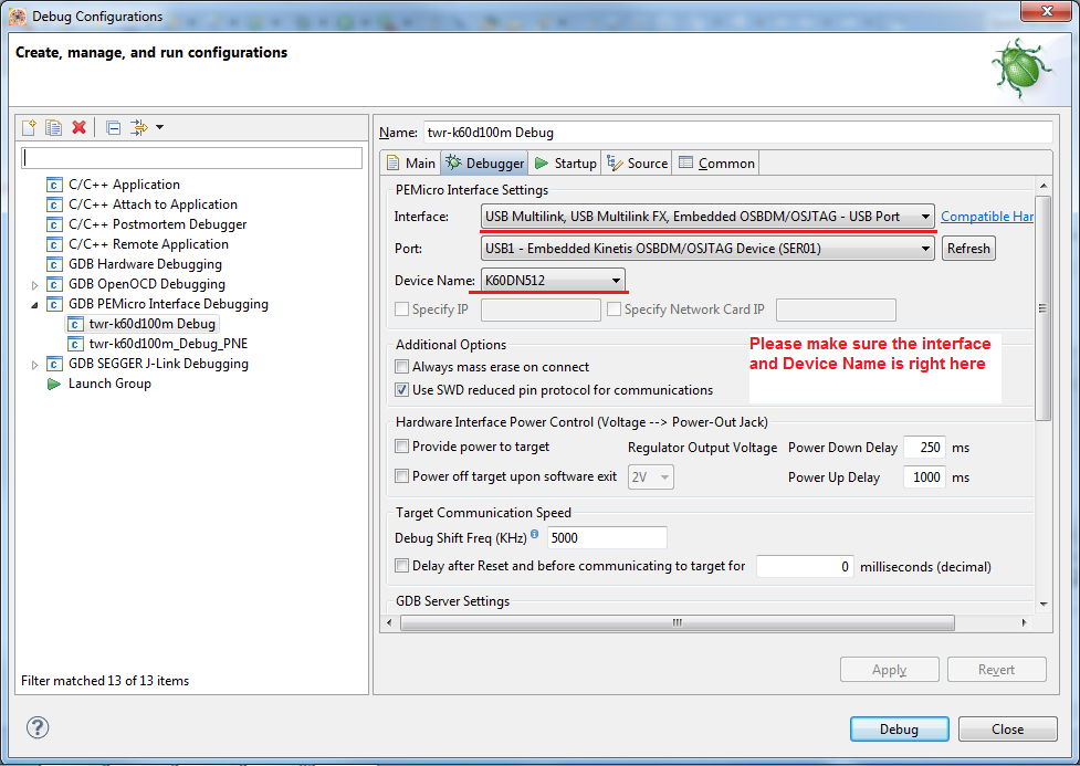
Are you really using SWD in your custom board? If not uncheck the "Use SWD reduced pin..." option.
Regards!,
Jorge Gonzalez
-----------------------------------------------------------------------------------------------------------------------
Note: If this post answers your question, please click the Correct Answer button. Thank you!
-----------------------------------------------------------------------------------------------------------------------
- 新着としてマーク
- ブックマーク
- 購読
- ミュート
- RSS フィードを購読する
- ハイライト
- 印刷
- 不適切なコンテンツを報告
Jorge,
Using SWD in both KDE and CW. Unchecked just to try but didn’t work.
Don
- 新着としてマーク
- ブックマーク
- 購読
- ミュート
- RSS フィードを購読する
- ハイライト
- 印刷
- 不適切なコンテンツを報告
Well, I tried deleting KDS2.0.0 and CW 10.6 and reinstalling. Still only runs with CW10.6. I have replaced the controller and duplicated the problem on a second board.
- 新着としてマーク
- ブックマーク
- 購読
- ミュート
- RSS フィードを購読する
- ハイライト
- 印刷
- 不適切なコンテンツを報告
Hi Donald Porada,
There might be some problem with the connection configuration of the KDS project.
Some connection configuration information are stored in the folder .metadata of the workspace.
Even if a re-installation of KDS, this connection configuration information will be restored from .metadata when import project.
could you please delete the .metadata folder of current workspace or creating a new workspace and then creating a new project for testing?
(when launching KDS, you will see there is a window asking the workspace, just change it to another name)
please let me know if it helps!
- 新着としてマーク
- ブックマーク
- 購読
- ミュート
- RSS フィードを購読する
- ハイライト
- 印刷
- 不適切なコンテンツを報告
I tried deleting the .metadata and a new workspace. Neither helped. The console message is slightly different if it helps.
P&E GDB Server, Version 5.13.02.00
Copyright 2014, P&E Microcomputer Systems Inc, All rights reserved
Loading library C:\Freescale\KDS_2.0.0\eclipse\plugins\com.pemicro.debug.gdbjtag.pne_1.1.7.201410171532\win32\gdi\unit_ngs_arm_internal.dll ... Done.
Command line arguments: -device=K60FN1M0 -startserver -singlesession -serverport=7224 -interface=USBMULTILINK -speed=5000 -port=USB1 -USE_CYCLONEPRO_RELAYS=0 -FORCE_MASS_ERASE=0
Device selected is k60fn1m0
User Specified Hardware Selection : Interface=USBMULTILINK and Port=USB1
Connecting to target.
P&E Interface detected - Flash Version 7.09
Device is K60FN1M0.
Mode is In-Circuit Debug.
'Kinetis' is a registered trademark of Freescale.
(C)opyright 2012, P&E Microcomputer Systems, Inc. (www.pemicro.com)
API version is 101
Server running on 127.0.0.1:7224
Connection from "127.0.0.1" via 127.0.0.1
Copyright 2012 P&E Microcomputer Systems,Inc.
Command Line :C:\Freescale\KDS_2.0.0\eclipse\plugins\com.pemicro.debug.gdbjtag.pne_1.1.7.201410171532\win32\pegdbserver_console -device=K60FN1M0 -startserver -singlesession -serverport=7224 -interface=USBMULTILINK -speed=5000 -port=USB1 -USE_CYCLONEPRO_R
CMD>RE
Initializing.
Cannot enter background mode. Check connections.
Error Resetting device for programming.
PE-ERROR: Error downloading to the device.
Preset breakpoint encountered.
- 新着としてマーク
- ブックマーク
- 購読
- ミュート
- RSS フィードを購読する
- ハイライト
- 印刷
- 不適切なコンテンツを報告
Greetings,
From your log, it shows that the multilink is able to detect your target chip but when it tries to reset it fails to enter debug mode. A few things to try:
1) Try lowering the debug shift frequency. Compare the value you used in CW10.6 to the one in KDS.
2) Update your P&E plugin. It should not make a huge difference for Universal FX rev A, but worth trying. This can be done by going to Help -> Install new software.. Then select PEMicro from the dropdown box and check the PEMicro Software plugin and go through the install wizard.
3) Do you have any unique hardware like an external watchdog, reset circuitry, system bus chip, custom adapters, custom ribbon cables, or other hardware between the multilink and the chip?
Takao Yamada
P&E Microcomputer Systems
- 新着としてマーク
- ブックマーク
- 購読
- ミュート
- RSS フィードを購読する
- ハイライト
- 印刷
- 不適切なコンテンツを報告
Takao,
1) The setting is the same. I tried lowering to 1 MHz with the same results.
2) I updated the plugin with no effect.
3) No special hardware, just a 10K pullup.
Thank you,
Don Porada
- 新着としてマーク
- ブックマーク
- 購読
- ミュート
- RSS フィードを購読する
- ハイライト
- 印刷
- 不適切なコンテンツを報告
Greetings,
This is such a bizarre issue. I have the exact same setup where I have CW10.6 and KDS2.0 on my machine and hooked up to a USB multilink universal FX rev A to a K60FN1M0 tower board and I have no issues with either software.
Create a new bareboard KDS project, and without any code changes and with minimal settings changes are you getting the same errors?
Make sure no other Freescale or P&E software is running and try power-cycling the target and multilink before each attempt. If you have an oscilloscope, you should set a trigger on reset and monitor the TDI, TDO, and TCK.
Takao Yamada
P&E Microcomputer Systems
- 新着としてマーク
- ブックマーク
- 購読
- ミュート
- RSS フィードを購読する
- ハイライト
- 印刷
- 不適切なコンテンツを報告
Aren't the pins you are talking about used in the JTAG mode? Are these pins also used in the SWD mode, I thought it used SWD_DIO, SWD_CLK, and RESET.
- 新着としてマーク
- ブックマーク
- 購読
- ミュート
- RSS フィードを購読する
- ハイライト
- 印刷
- 不適切なコンテンツを報告
Greetings,
Yes my answer was towards JTAG since earlier Jorge Gonzalez of Freescale noted that you should try unchecking SWD option. But if you plan on using SWD, then you are correct that you should monitor SWD_DIO, SWD_CLK, and set the trigger on RESET.
Takao Yamada
P&E Microcomputer Systems
- 新着としてマーク
- ブックマーク
- 購読
- ミュート
- RSS フィードを購読する
- ハイライト
- 印刷
- 不適切なコンテンツを報告
When the reset is low, here's what I get. The top trace being the DIO, and the bottom being clock.

- 新着としてマーク
- ブックマーク
- 購読
- ミュート
- RSS フィードを購読する
- ハイライト
- 印刷
- 不適切なコンテンツを報告
Greetings,
Thank you for the screenshot of your scope. This shows that the multilink is talking to the chip and trying to enter debug mode. However, I need the full picture. What happens when reset goes back up to high? Or does it ever go back to high? Is there any activity on DIO and TCK? If there is not, I would advise adding more reset delay than just 50ms. Maybe 200ms.
Takao Yamada
- 新着としてマーク
- ブックマーク
- 購読
- ミュート
- RSS フィードを購読する
- ハイライト
- 印刷
- 不適切なコンテンツを報告
OK, with the delay set to 0, the reset goes low, communication happens every 5ms. This repeats for 85ms and then the reset goes high. After the reset goes high, the communication happens again in 5ms intervals 5 more times. Then there is a 20ms delay, and then a large packet of information is sent.
What should I be seeing?
Don
- 新着としてマーク
- ブックマーク
- 購読
- ミュート
- RSS フィードを購読する
- ハイライト
- 印刷
- 不適切なコンテンツを報告
Oh, the 200ms delay had no effect.
- 新着としてマーク
- ブックマーク
- 購読
- ミュート
- RSS フィードを購読する
- ハイライト
- 印刷
- 不適切なコンテンツを報告
Here's what I have.
