
- Forums
- Product Forums
- General Purpose MicrocontrollersGeneral Purpose Microcontrollers
- i.MX Forumsi.MX Forums
- QorIQ Processing PlatformsQorIQ Processing Platforms
- Identification and SecurityIdentification and Security
- Power ManagementPower Management
- Wireless ConnectivityWireless Connectivity
- RFID / NFCRFID / NFC
- Advanced AnalogAdvanced Analog
- Neural Processing UnitsNeural Processing Units
- MCX Microcontrollers
- S32G
- S32K
- S32V
- MPC5xxx
- Other NXP Products
- S12 / MagniV Microcontrollers
- Powertrain and Electrification Analog Drivers
- Sensors
- Vybrid Processors
- Digital Signal Controllers
- 8-bit Microcontrollers
- ColdFire/68K Microcontrollers and Processors
- PowerQUICC Processors
- OSBDM and TBDML
- S32M
- S32Z/E
-
- Solution Forums
- Software Forums
- MCUXpresso Software and ToolsMCUXpresso Software and Tools
- CodeWarriorCodeWarrior
- MQX Software SolutionsMQX Software Solutions
- Model-Based Design Toolbox (MBDT)Model-Based Design Toolbox (MBDT)
- FreeMASTER
- eIQ Machine Learning Software
- Embedded Software and Tools Clinic
- S32 SDK
- S32 Design Studio
- GUI Guider
- Zephyr Project
- Voice Technology
- Application Software Packs
- Secure Provisioning SDK (SPSDK)
- Processor Expert Software
- Generative AI & LLMs
-
- Topics
- Mobile Robotics - Drones and RoversMobile Robotics - Drones and Rovers
- NXP Training ContentNXP Training Content
- University ProgramsUniversity Programs
- Rapid IoT
- NXP Designs
- SafeAssure-Community
- OSS Security & Maintenance
- Using Our Community
-
- Cloud Lab Forums
-
- Knowledge Bases
- ARM Microcontrollers
- i.MX Processors
- Identification and Security
- Model-Based Design Toolbox (MBDT)
- QorIQ Processing Platforms
- S32 Automotive Processing Platform
- Wireless Connectivity
- CodeWarrior
- MCUXpresso Suite of Software and Tools
- MQX Software Solutions
- RFID / NFC
- Advanced Analog
- Neural Processing Units
-
- NXP Tech Blogs
- Home
- :
- MCUXpresso Software and Tools
- :
- Kinetis Design Studio
- :
- Accessing PORT pins on FRDM-KL25Z
Accessing PORT pins on FRDM-KL25Z
- Subscribe to RSS Feed
- Mark Topic as New
- Mark Topic as Read
- Float this Topic for Current User
- Bookmark
- Subscribe
- Mute
- Printer Friendly Page

- Mark as New
- Bookmark
- Subscribe
- Mute
- Subscribe to RSS Feed
- Permalink
- Report Inappropriate Content
Hey guys,
This may seem a little awkward coz im a lil confused as to where to post this article/query but here it is. Ive been developing firmwares for Microchip controllers.
This is my first encounter with Freescale semiconductors. Im currently working on the FRDM-KL25Z and chose the Kinetis Design Studio as my IDE. Well the problem is im not used to automatic code generation provided by Processor Expert hence tried looking for means of accessing the registers manually to perform the initial ritual of Blinking LED. Currently Im lost with how to set the port direction as input/output and how to gain access of individual Port Pins. If you could help me with the libraries or any tutorial that provides a walkthrough on using KL25Z on KDS 3.0 i would be great. Btw i was able to perform debug on an empty loop just to know that the debugger is working fine.
Solved! Go to Solution.

 DavidS
- Mark as New
- Bookmark
- Subscribe
- Mute
- Subscribe to RSS Feed
- Permalink
- Report Inappropriate Content
Hi Nelson,
Please review following document:
C:\Freescale\KSDK_1.2.0\doc\Kinetis SDK v.1.2.0 Demo Applications User's Guide.pdf
Then load up the C:\Freescale\KSDK_1.2.0\examples\frdmkl25z\demo_apps\hello_world\kds project.
I use the Import->Project of Projects->Existing Projects Sets and point it to the path above. This opens the library project and application project. Build library first...then application.
The hello world gets prints to terminal.
The green LED blinks.
You can play around with the various LED1_<> marco's in the board.h.
Like: LED1_TOGGLE, LED1_ON, LED1_OFF, etc..
Regards,
David
DavidS
- Mark as New
- Bookmark
- Subscribe
- Mute
- Subscribe to RSS Feed
- Permalink
- Report Inappropriate Content
Hi Nelson,
Please review following document:
C:\Freescale\KSDK_1.2.0\doc\Kinetis SDK v.1.2.0 Demo Applications User's Guide.pdf
Then load up the C:\Freescale\KSDK_1.2.0\examples\frdmkl25z\demo_apps\hello_world\kds project.
I use the Import->Project of Projects->Existing Projects Sets and point it to the path above. This opens the library project and application project. Build library first...then application.
The hello world gets prints to terminal.
The green LED blinks.
You can play around with the various LED1_<> marco's in the board.h.
Like: LED1_TOGGLE, LED1_ON, LED1_OFF, etc..
Regards,
David
- Mark as New
- Bookmark
- Subscribe
- Mute
- Subscribe to RSS Feed
- Permalink
- Report Inappropriate Content
Hi David,
I checked the location mentioned for examples but this is what ive got from my KDS_3.0 install.
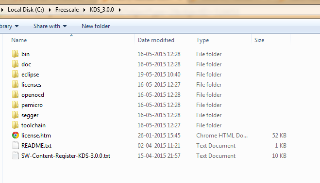
Examples are missing. Do I have to download them separately?
DavidS
- Mark as New
- Bookmark
- Subscribe
- Mute
- Subscribe to RSS Feed
- Permalink
- Report Inappropriate Content
Hi Nelson,
You are looking in the KDS path.
Please try the KSDK (yes too many acronyms).
C:\Freescale\KSDK_1.2.0\examples\frdmkl25z\demo_apps\hello_world\kds
Regards,
David
- Mark as New
- Bookmark
- Subscribe
- Mute
- Subscribe to RSS Feed
- Permalink
- Report Inappropriate Content
Hi David,
Thanks for pointing that out but I had to install KSDK_1.20 separately from freescale site. The example worked fine. Also i tried toggling PTB0 by making changes in gpio_pins.h
Now i wanted to know how is the following statement liked to the actual MCU pin register mentioned in the refernce manual Rev 3.0 Sept 2012:
GPIO_MAKE_PIN(GPIOB_IDX, 0),
where,
GPIO_MAKE can be found in fsl_gpio_driver.h
GPIO_IDX can be found in MKL25Z4_extension.h
while the reference manual on pg.178 PORTB_PCR0 has no relation to the same port pin mentioned above. I may be wrong with this assumption but curious to know the relation between whats mentioned in refernce manual to the headers provided.
Regards,
Nelson
DavidS
- Mark as New
- Bookmark
- Subscribe
- Mute
- Subscribe to RSS Feed
- Permalink
- Report Inappropriate Content
Hi Nelson,
It does take a little detective work to understand the operation and configuration of the GPIO. Let me try to explain.
The KSDK->platform->gpio->drivers->fsl_gpio_driver.h has a macro for combine a PORTx + pin location within the register into one value with the following:
/*! @brief Combines the port number and the pin number into a single scalar value. */
#define GPIO_MAKE_PIN(r,p) (((r)<< GPIO_PORT_SHIFT) | (p))
In the application there is a gpio_pins.h header.
I accumulates all the pins that are going to be used as GPIO and places in a enum structure as follows:
/*! @brief Pin names */
enum _gpio_pins_pinNames{
kGpioSW2 = GPIO_MAKE_PIN(GPIOC_IDX, 6U),
kGpioSW3 = GPIO_MAKE_PIN(GPIOA_IDX, 4U),
kGpioSdhc0Cd = GPIO_MAKE_PIN(GPIOE_IDX, 6U),
kGpioLED1 = GPIO_MAKE_PIN(GPIOE_IDX, 26U),
kGpioLED2 = GPIO_MAKE_PIN(GPIOB_IDX, 22U),
kGpioLED3 = GPIO_MAKE_PIN(GPIOB_IDX, 21U),
};
As example on frdmk64 since I have that project opened kGpioLED1
"gpio_pins.c" will define parameters for the gpio pin such as input/output, slewrate, Open Drain or not, Drive Strength using the following structure as example:
const gpio_output_pin_user_config_t ledPins[] = {
{
.pinName = kGpioLED1,
.config.outputLogic = 1,
.config.slewRate = kPortSlowSlewRate,
.config.isOpenDrainEnabled = false,
.config.driveStrength = kPortLowDriveStrength,
},
....other pin definitions that get used by the
So that is a pre-defined set of pins to control the tri-colored LED on the frdm-k64f Freedom board.
In the example application, gpio_example_frdmk64f (since the frdmkl25z doesn't have gpio example yet) the main.c defines one output gpio pin to control the kGpioLED1 as:
// Define gpio output pin config structure LED1.
gpio_output_pin_user_config_t outputPin[] = {
{
.pinName = kGpioLED1,
.config.outputLogic = 0,
#if FSL_FEATURE_PORT_HAS_SLEW_RATE
.config.slewRate = kPortFastSlewRate,
#endif
#if FSL_FEATURE_PORT_HAS_DRIVE_STRENGTH
.config.driveStrength = kPortHighDriveStrength,
#endif
},
{
.pinName = GPIO_PINS_OUT_OF_RANGE,
}
};
Later in the code the gpio is initialized:
// Init LED1, SW1.
GPIO_DRV_Init(inputPin, outputPin);
Then the GPIO Peripheral Driver routines can be used:
// Turn LED1 on.
GPIO_DRV_ClearPinOutput(kGpioLED1);
Summary: Many ways to implement GPIO and organize then individually or as a group.....or come up with your own method just by using the HAL drivers.
Regards,
David
