- Forums
- Product Forums
- General Purpose MicrocontrollersGeneral Purpose Microcontrollers
- i.MX Forumsi.MX Forums
- QorIQ Processing PlatformsQorIQ Processing Platforms
- Identification and SecurityIdentification and Security
- Power ManagementPower Management
- Wireless ConnectivityWireless Connectivity
- RFID / NFCRFID / NFC
- Advanced AnalogAdvanced Analog
- MCX Microcontrollers
- S32G
- S32K
- S32V
- MPC5xxx
- Other NXP Products
- S12 / MagniV Microcontrollers
- Powertrain and Electrification Analog Drivers
- Sensors
- Vybrid Processors
- Digital Signal Controllers
- 8-bit Microcontrollers
- ColdFire/68K Microcontrollers and Processors
- PowerQUICC Processors
- OSBDM and TBDML
- S32M
- S32Z/E
-
- Solution Forums
- Software Forums
- MCUXpresso Software and ToolsMCUXpresso Software and Tools
- CodeWarriorCodeWarrior
- MQX Software SolutionsMQX Software Solutions
- Model-Based Design Toolbox (MBDT)Model-Based Design Toolbox (MBDT)
- FreeMASTER
- eIQ Machine Learning Software
- Embedded Software and Tools Clinic
- S32 SDK
- S32 Design Studio
- GUI Guider
- Zephyr Project
- Voice Technology
- Application Software Packs
- Secure Provisioning SDK (SPSDK)
- Processor Expert Software
- Generative AI & LLMs
-
- Topics
- Mobile Robotics - Drones and RoversMobile Robotics - Drones and Rovers
- NXP Training ContentNXP Training Content
- University ProgramsUniversity Programs
- Rapid IoT
- NXP Designs
- SafeAssure-Community
- OSS Security & Maintenance
- Using Our Community
-
- Cloud Lab Forums
-
- Knowledge Bases
- ARM Microcontrollers
- i.MX Processors
- Identification and Security
- Model-Based Design Toolbox (MBDT)
- QorIQ Processing Platforms
- S32 Automotive Processing Platform
- Wireless Connectivity
- CodeWarrior
- MCUXpresso Suite of Software and Tools
- MQX Software Solutions
- RFID / NFC
- Advanced Analog
-
- NXP Tech Blogs
- Home
- :
- CodeWarrior
- :
- CodeWarrior for MCU
- :
- eMIOS_IC Data acquisition problem
eMIOS_IC Data acquisition problem
eMIOS_IC Data acquisition problem
Hi:
I have a problem using the eMIOS_IC function. Can anyone help me?
I'm using eMIOS IC to collect data on a square wave,The eMIOS return a value stable at 20183,
However, an unusual triangular wave occurs(The abnormal waveform is shown in the red coil in the picture below),
I found that when this situation occurs, eMIOS will return multiple values, such as 8023、32。
in this abnormal waveform,EMIOS IC return values are not stable,Is this normal?
Anybody know why,thank you.
Hello,
I'm trying to use EMIOS_IC component but it's not working..
I'd like to read the frequency of a square wave.
I have a DEVKIT-MPC5748G and use S32-Design with processor expert.
EMIOS_DRV_IC_InitInputCaptureMode(INST_EMIOS_MC1, 11, &eMIOS_Ic1_ICChnConfig0);
EMIOS_DRV_IC_GetLastMeasurement(INST_EMIOS_MC1, 11, &Period);
The input signal period is 50ms but 'Period' variable is always 0.
Other doubt is if the emios_qd component works? If so, is there any example of how to use?
Thanks,
Best Regards
João Paulo
Hi,
multiple values means you do not capture single value on this falling triangular "edge" but you get several captures?
Could be caused by noisy signal and output signal from input buffer oscillate along the threshold.
Try to enable hysteresis on input pin or enable input filter, if available on your MCU, not sure what you use.
BR, Petr
Hi Petr
Thanks for your reply,I have got the actual waveform input to the MCU from the hardware department.
Please look at the following picture:
I used the "EMIOS_DRV_IC_GetLastMeasurement()" interface in the SDK to get the data returned by eMIOS,
At t1 and t2, the return data were normal(eMIOS return data is 20183),After t3, the input signal remains high,and the value returned by the "EMIOS_DRV_IC_GetLastMeasurement()" will remain the value collected in t3(eMIOS return data is 14190) and will not be updated anymore.
I want to know why the eMIOS return data is keep in t3(return data is 14190) when the input signal is keep high?
Is there a way to update the data when the input signal keep high?
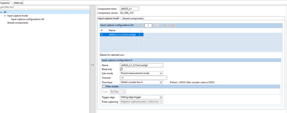
I used the eMIOS IC function, and the configuration contents are as follows(by S32 Design Studio for Power):
1、eMIOS_MC Configuration
2、eMIOS_IC Configuration
Dear Petr
Thanks for your reply,
I also tried configuring eMIOS_IC to measure width of high pulse mode(Positive captured pulse / active high),
however,when the input signal keep high,eMIOS return data also keep last value.
It that mean eMIOS_IC cannot measure 100% duty signal?
No matter positive captured mode or negative captured mode, they both need a high pulse and a low pulse to complete the measure?
Hi,
in IPWM mode on the trailing edge the flag is set and captured values for both edges can be read from respective registers, because they are updated on this edge.
See mode description in the device Reference Manual.
If there is no trailing edge, registers are not updated and keep last values.
So yes, you cannot measure 100% duty signal, you need 2 opposite edges, it is pulse width measurement.
BR, Petr


