
- Forums
- Product Forums
- General Purpose MicrocontrollersGeneral Purpose Microcontrollers
- i.MX Forumsi.MX Forums
- QorIQ Processing PlatformsQorIQ Processing Platforms
- Identification and SecurityIdentification and Security
- Power ManagementPower Management
- Wireless ConnectivityWireless Connectivity
- RFID / NFCRFID / NFC
- Advanced AnalogAdvanced Analog
- Neural Processing UnitsNeural Processing Units
- MCX Microcontrollers
- S32G
- S32K
- S32V
- MPC5xxx
- Other NXP Products
- S12 / MagniV Microcontrollers
- Powertrain and Electrification Analog Drivers
- Sensors
- Vybrid Processors
- Digital Signal Controllers
- 8-bit Microcontrollers
- ColdFire/68K Microcontrollers and Processors
- PowerQUICC Processors
- OSBDM and TBDML
- S32M
- S32Z/E
-
- Solution Forums
- Software Forums
- MCUXpresso Software and ToolsMCUXpresso Software and Tools
- CodeWarriorCodeWarrior
- MQX Software SolutionsMQX Software Solutions
- Model-Based Design Toolbox (MBDT)Model-Based Design Toolbox (MBDT)
- FreeMASTER
- eIQ Machine Learning Software
- Embedded Software and Tools Clinic
- S32 SDK
- S32 Design Studio
- GUI Guider
- Zephyr Project
- Voice Technology
- Application Software Packs
- Secure Provisioning SDK (SPSDK)
- Processor Expert Software
- Generative AI & LLMs
-
- Topics
- Mobile Robotics - Drones and RoversMobile Robotics - Drones and Rovers
- NXP Training ContentNXP Training Content
- University ProgramsUniversity Programs
- Rapid IoT
- NXP Designs
- SafeAssure-Community
- OSS Security & Maintenance
- Using Our Community
-
- Cloud Lab Forums
-
- Knowledge Bases
- ARM Microcontrollers
- i.MX Processors
- Identification and Security
- Model-Based Design Toolbox (MBDT)
- QorIQ Processing Platforms
- S32 Automotive Processing Platform
- Wireless Connectivity
- CodeWarrior
- MCUXpresso Suite of Software and Tools
- MQX Software Solutions
- RFID / NFC
- Advanced Analog
- Neural Processing Units
-
- NXP Tech Blogs
- Home
- :
- General Purpose Microcontrollers
- :
- Kinetis Microcontrollers
- :
- k24 clock configurations for external 16MHz osc and PLL
k24 clock configurations for external 16MHz osc and PLL
- Subscribe to RSS Feed
- Mark Topic as New
- Mark Topic as Read
- Float this Topic for Current User
- Bookmark
- Subscribe
- Mute
- Printer Friendly Page
k24 clock configurations for external 16MHz osc and PLL
- Mark as New
- Bookmark
- Subscribe
- Mute
- Subscribe to RSS Feed
- Permalink
- Report Inappropriate Content
Hello,
I'm trying to get a custom board with a MK24FN1M0VLL12 with an external 16MHz oscillator. I'd like to use PLL and 120MHz system clock. I've tried using the KDS2.x new project wizard to start the project and then just dropped in my clock_config files from the MCUXpresso online tool. When trying to setup the clock's I keep getting stuck in a while loop in the function CLOCK_SetPbeMode(). It appears the clock status bit are not set correctly. I did notice that the MCG_C1 and MCG_C2 register values that are outputted from the online tool do not match what's in the registers when debugging.
Anyone know how to properly configure the clocks using an external 16MHz oscillator?
--------- While loop where i'm getting stuck is in fsl_clock.c/CLOCK_SetPbeMode() ---------
/* Wait for CLKST clock status bits to show clock source is ext ref clk */
while ((MCG->S & (MCG_S_IREFST_MASK | MCG_S_CLKST_MASK)) !=
(MCG_S_IREFST(kMCG_FllSrcExternal) | MCG_S_CLKST(kMCG_ClkOutStatExt)))
{
}
Original Attachment has been moved to: k24TestProject.zip
- Mark as New
- Bookmark
- Subscribe
- Mute
- Subscribe to RSS Feed
- Permalink
- Report Inappropriate Content
Alex,
Did you use the functions provided in the clocks_config.c or did you just drop Mark's code in? I have the exact same setup as you and I'm getting stuck in the exact same spot. I've gotten this to work in GCC by hand cranking the values and configuring the clocks much like Mark does (so I know I have the right values) but I would really like to get the functions in clock_config.c to work. Any chance you could share your file with me?
- Mark as New
- Bookmark
- Subscribe
- Mute
- Subscribe to RSS Feed
- Permalink
- Report Inappropriate Content
Hi
K24F120 with 16MHz crystal to 120MHz PLL (actual hex value in square brackets):
MCG_C2 = (MCG_C2_FREQ_RANGE | MCG_C2_GAIN_MODE | MCG_C2_EREFS | MCG_C2_LOCRE0); // [0xa4] select crystal oscillator and select a suitable range
MCG_C1 = (MCG_C1_CLKS_EXTERN_CLK | MCG_C1_FRDIV_VALUE); // [0xa0] switch to external source (the FLL input clock is set to as close to its input range as possible, although this is not absolutely necessary if the FLL will not be used)
while ((MCG_S & MCG_S_OSCINIT) == 0) {} // loop until the crystal source has been selected
while ((MCG_S & MCG_S_IREFST) != 0) {} // loop until the FLL source is no longer the internal reference clock
while ((MCG_S & MCG_S_CLKST_MASK) != MCG_S_CLKST_EXTERN_CLK) {} // loop until the external reference clock source is valid
MCG_C5 = ((CLOCK_DIV - 1) | MCG_C5_PLLSTEN0); // [0x23] now move from state FEE to state PBE (or FBE) PLL remains enabled in normal stop modes
MCG_C6 = ((CLOCK_MUL - MCG_C6_VDIV0_LOWEST) | MCG_C6_PLLS); // [0x46] set the PLL multiplication factor
while ((MCG_S & MCG_S_PLLST) == 0) {} // loop until the PLLS clock source becomes valid
while ((MCG_S & MCG_S_LOCK) == 0) {} // loop until PLL locks
SIM_CLKDIV1 = (((SYSTEM_CLOCK_DIVIDE - 1) << 28) | ((BUS_CLOCK_DIVIDE - 1) << 24) | ((FLEX_CLOCK_DIVIDE - 1) << 20) | ((FLASH_CLOCK_DIVIDE - 1) << 16)); // [0x01240000] prepare bus clock divides
MCG_C1 = (MCG_C1_CLKS_PLL_FLL | MCG_C1_FRDIV_1024); // [0x28] finally move from PBE to PEE mode - switch to PLL clock
while ((MCG_S & MCG_S_CLKST_MASK) != MCG_S_CLKST_PLL) {} // loop until the PLL clock is selected
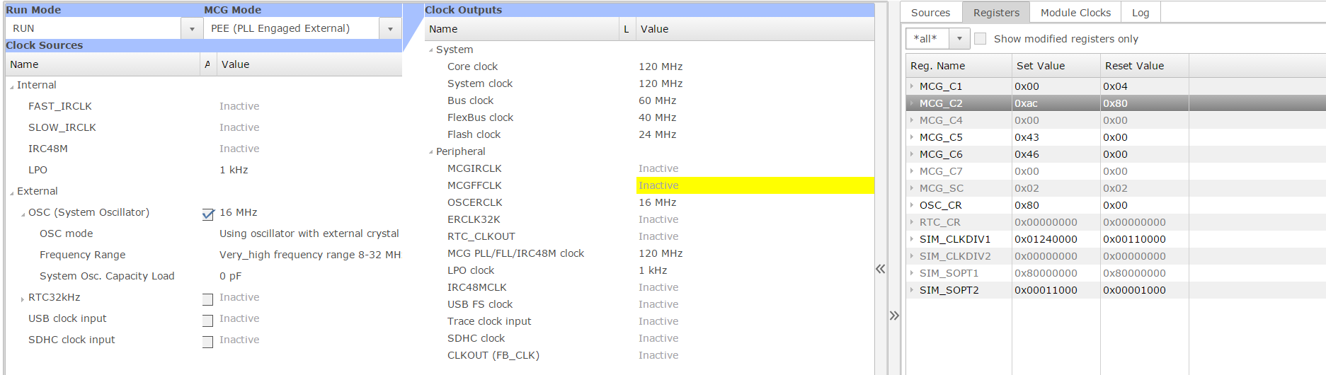
Beware that the first write to MCG_C2 is 0xa4 if the crystal circuit is not loaded with caps and a feedback resistor. If there is loading 0xac is needed so that the crytsal oscillator can start.
Simulation of the config in uTasker K24 project below, showing clock rates achieved.
Regards
Mark

- Mark as New
- Bookmark
- Subscribe
- Mute
- Subscribe to RSS Feed
- Permalink
- Report Inappropriate Content
Could you please list out the values of the #defines used in the bit checking used in the while loops
- Mark as New
- Bookmark
- Subscribe
- Mute
- Subscribe to RSS Feed
- Permalink
- Report Inappropriate Content
Hi
The names correspond to the register flag names and are below:
#define MCG_S_IRCST 0x01 // source of internal reference clock is the fast clock (4MHz IRC) rather than slow clock (32kHz)
#define MCG_S_OSCINIT 0x02 // set when the initialisation cycles of the crystal oscillator have completed
#define MCG_S_CLKST_FLL 0x00 // FLL output is selected
#define MCG_S_CLKST_INTERN_CLK 0x04 // internal reference clock is selected
#define MCG_S_CLKST_EXTERN_CLK 0x08 // external reference clock is selected
#define MCG_S_CLKST_PLL 0x0c // PLL output is selected
#define MCG_S_CLKST_MASK 0x0c // clock selection field mask
#define MCG_S_IREFST 0x10 // FLL reference source is internal reference clock
#define MCG_S_PLLST_FLL 0x00 // source of PLLS is FLL clock
#define MCG_S_PLLST 0x20 // source of PLLS is PLL clock
#define MCG_S_LOCK 0x40 // PLL has acquired lock
#define MCG_S_LOLS 0x80 // PLL has lost lock since LOLS was last cleared
and can be found at the uTasker open source K24 project: http://www.utasker.com/forum/index.php?topic=1721.msg7086#msg7086
Regards
Mark
- Mark as New
- Bookmark
- Subscribe
- Mute
- Subscribe to RSS Feed
- Permalink
- Report Inappropriate Content
Thanks Mark. That got me past the while loops but i'm still having problems with UART > 38400 baud rates. Thank you!
- Mark as New
- Bookmark
- Subscribe
- Mute
- Subscribe to RSS Feed
- Permalink
- Report Inappropriate Content
UART0 and UART1:
UARTn_C4 = 0x0a;
UARTn_BDH = 0x00;
UARTn_BDL = 0xc3;
UART2 and UART3:
UARTn_C4 = 0x15;
UARTn_BDH = 0x00;
UARTn_BDL = 0x61;
Valid for 120MHz system and 60MHz bus clock.
http://www.utasker.com/docs/uTasker/uTaskerUART.PDF
Full interrupt/DMA solution at the project link given previously.
Regards
Mark
- Mark as New
- Bookmark
- Subscribe
- Mute
- Subscribe to RSS Feed
- Permalink
- Report Inappropriate Content
Yeah I'm using the UART driver example from KSDK 2.1 and you set the baud rate and it generates the C4,BDH and BDL for you. I verrified using Processor Export that the values create the correct baud rate. My issue is if I try to use a baud rate higher than 38400 I get errors on my logic analyzer and it appears the baud rate is not correct. For instance for 115200 the values are BDH 0x00 BDL 0x41 and C4 0x03 . Now that comes out to a baud rate of 115218.435 which obviously is not exact so i'm wondering do I have to change my core system clock to one where I can get exactly 115200? Not sure how flexible UART is with the timing.
- Mark as New
- Bookmark
- Subscribe
- Mute
- Subscribe to RSS Feed
- Permalink
- Report Inappropriate Content
Hi
115'218 is the best possible speed obtainable for 115'200.
It is 0.16% from the perfect value and so accurate enough for asynchronous use (which accepts about 1.5% inaccuracy). There is no need to change clock sources due to thus slight deviation.
Regards
Mark